Week 9 - Parametric study on Gate valve.
- AIM:-
To Run a Simulation On Parametric Valve Study On the Gate Valve Using ANSYS-FLUENT.
- OBJECTIVES:-
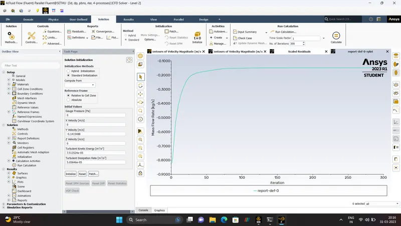
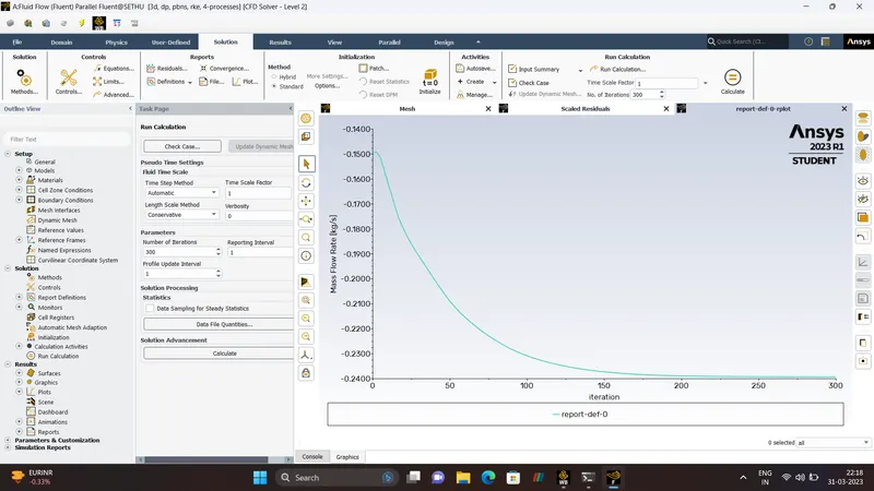
To Obtain the mass flow rates at the outlet for each design point.
To Calculate the flow coefficient and flow factor for each opening and plot the graph.
To Discuss the results of the mass flow rate and flow coefficient.
- PROCEDURE:-
SOURCE - WIKIPEDIA.
GATE VALVE.
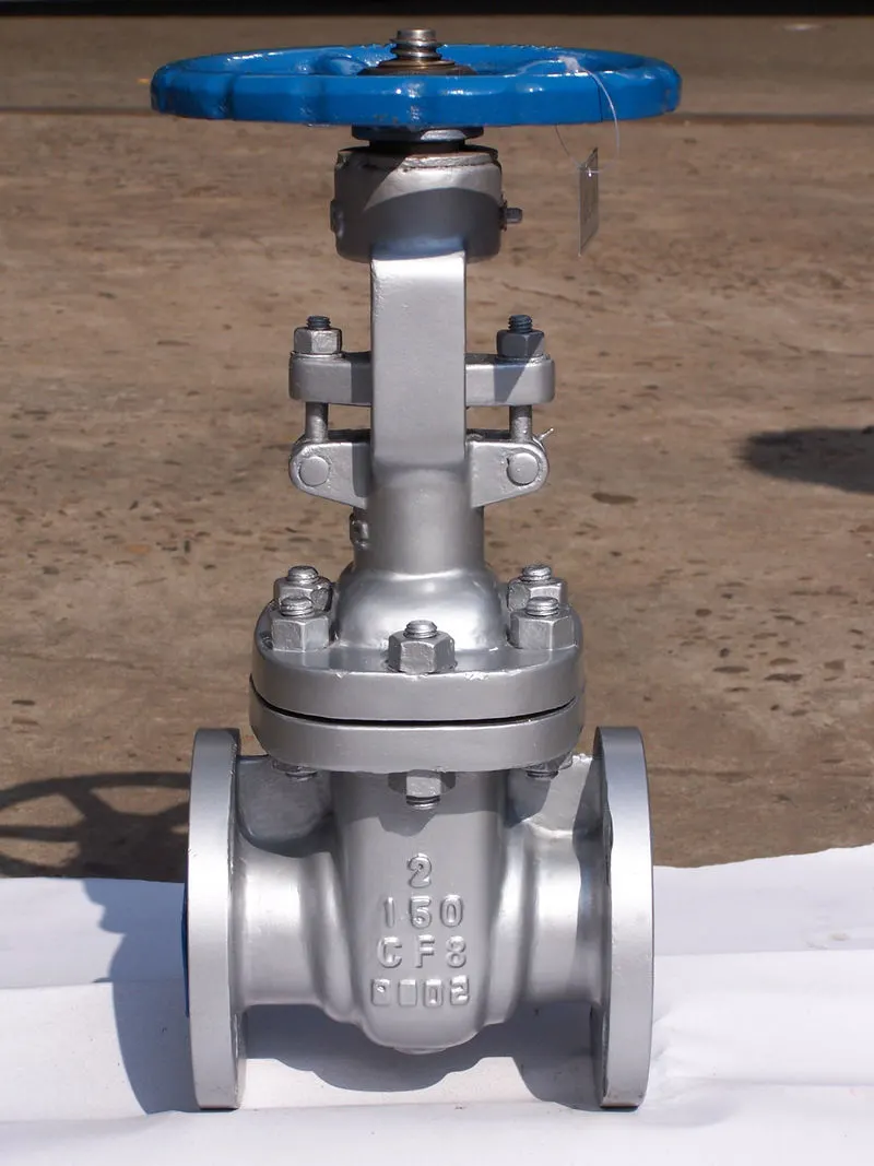
A gate valve, also known as a Sluice Valve, is a valve that opens by lifting a barrier(gate) out of the path of the fluid. Gate valve require very little Space along the pipe axis and hardly restrict the flow of fluid when the gate is fully opened. The gate faces can be parallel but are most commonly wedge-shaped (in order to be able to apply pressure on the sealing surface).
- TYPICAL USE.
Gate Valve are used to shut off the flow of liquids rather than for flow regulation, which is frequently done with a globe Valve. When fully Open, the typical gate Valve has no obstruction in the flow path generally varies in a non-liear manner as the gate is moved. This means that the flow rate does not change evenly with stem travel. Dependig on the construction, a partially open gate can vibrate from the fluid flow.
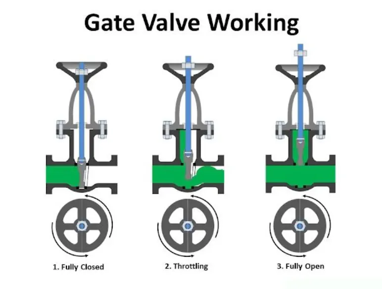
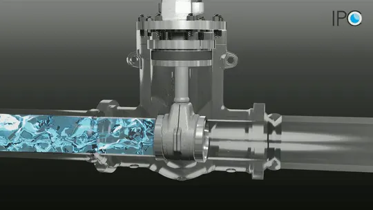
Gate Valve are mostly used with larger pipe diameter(from 2 to the largest pipelines) since they are less complex to construct than other types of valves in larger sizes.
At High Pressure, Friction can become a problem. As the gate is pushed against its guiding rail by the pressure of the medium, It becomes harder to operate the valve. Large Gate Valve are sometimes flitted with a bypass controlled by a smaller valve to be able to reduce the pressure before operating the gate valve itself.
Gate Valves without an extra sealing the ring on the gate or the seat are uesd in applications where minor leaking of the valve is not an issue, such as heating circuits or Sewer Pipes.
- CONSTRUCTION.
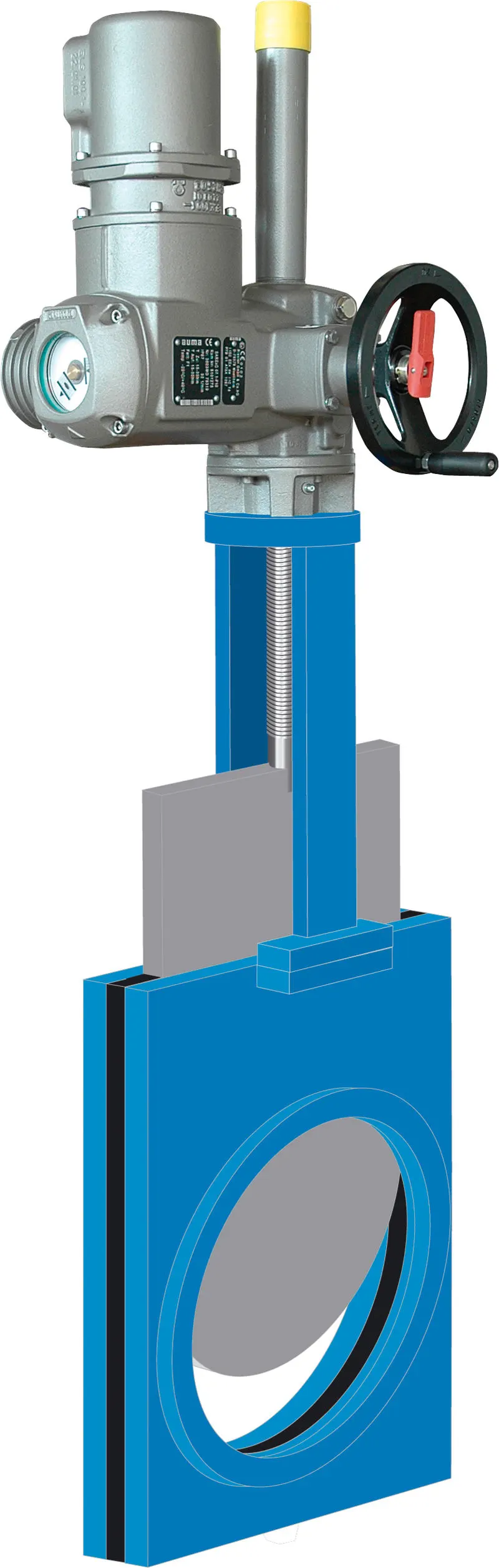
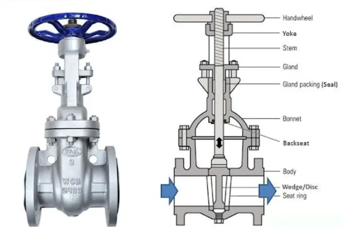
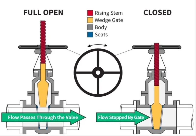
Common gate Valves are actuated by a threaded stem that connects the actuator(exmaple handwheel or motor)to the gate. They are characterises as having either a rising or nonrising stem, depending on which end of the stem is threaded. Rising Stem are fixed to the gate and rise and lower together as the valve is operated, providing a visual indication od valve position. The actuator is attached to a nut that is rotated around the threaded stem to move it. Nonrising stem valve are fixed to and rotate with, the actuator, and are threaded into the gate. They may have a pointer threaded onto the stem to indicate valve position, Since the gate's motion is concealed inside the valve. Nonrising Stems are used where vertical Shape is limited.
Gate Valve may have flanged ends drilled according to pipeline-compatible flange dimensional standards.
Gate Valves are typically constructed from Cast Iron, Cast Carbon Steel, Ductile Iron, Gunmetal, Stainless Steel, Alloy Steel and Forged Steels.
All-metal Gate Valves are used in Ultra-high Vaccum chambers to isolate the regions of the chamber.
- BONNET.
Bonnets Provide leakproof closure for the valve body. Gate Valves may have a screw-in, union or bolted bonnet. A Screw-in bonnet is the simplest, offering a durable, pressure-tight-seal. A union bonnet is suitable for applications requiring frequent insepections, and cleaning. It also gives the body added strength. A bolted bonnet is used for larger valves and higher pressure applications.
- PRESSURE SEAL BONNET.
Another type of bonnet construction in a gate valve is pressure seal bonnet. This construction is adopted for valves for high pressure service, typically in excess of 2250 psi (15 MPa). The Unique feature of the pressure seal bonnet is that the bonnet ends in a downward-facing cup that fits inside the body od the valve. As the internal pressure in the valve increases, the sides of the cups are forced outward. Improving the body-bonnet seal. Other constructions where the seal where the seal is provided by external clamping pressure tend to create leaks in teh body-bonnet joint.
- KNIFE GATE VALVE.
For Plastic Solids and High-Viscosity Slurries such as Paper pulp, A specialty valve known as a Knife Gate Valve is used to cut through the material to Stop the flow. A knife gate Valve is usually not wedge Shaped and has a tapered-knife-like edge on its lower Surface.
- SIMUATION
CFD follows flow of following processes.
PRE-PROCESSING.
Geometry Creation.
Mesh Generation and Quality Check.
Boundary and initial Condition Setup and choice of solver.
SOLVING
Choosing the type of Solver.
Choosing Solving Strategies (Time Step, Schemes, etc)
Solver Properties (Convergence Criteria, Relaxation, etc)
If applicable, making monitor points to understand solution accuracy.
POST-PROCESSING.
Understanding the data.
Graph Plots.
Contours,
Streamline, Vector Plots, etc.
Calculation Of Properties from the existing data.
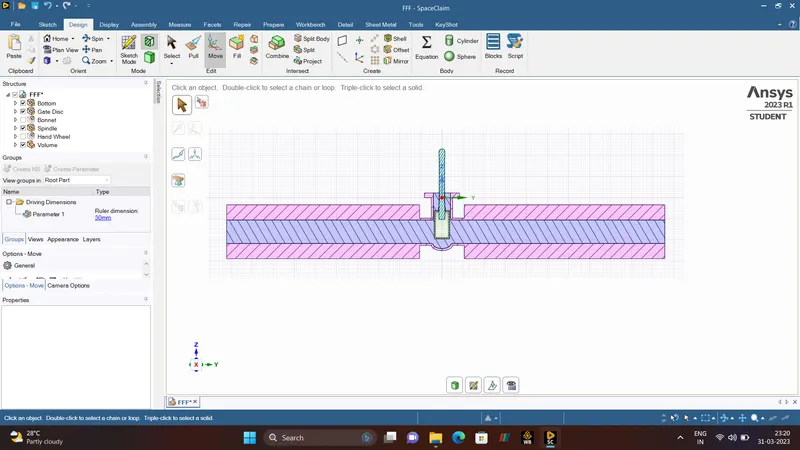
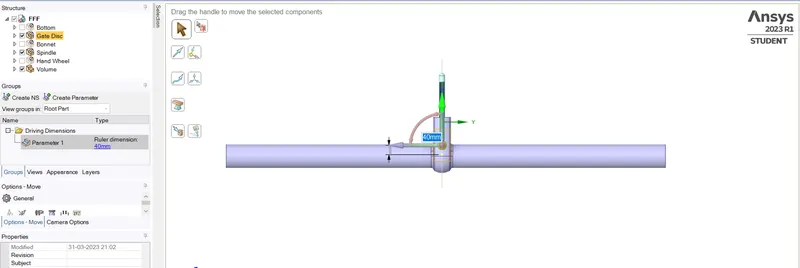
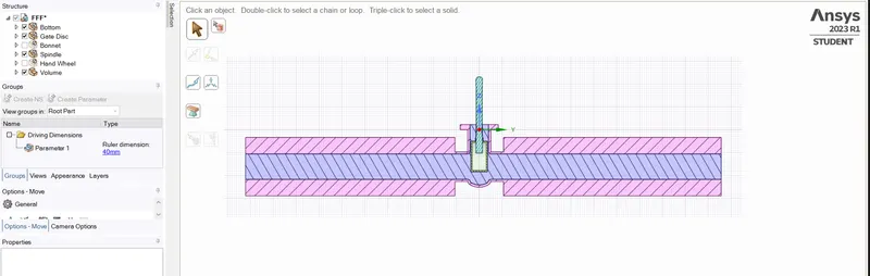
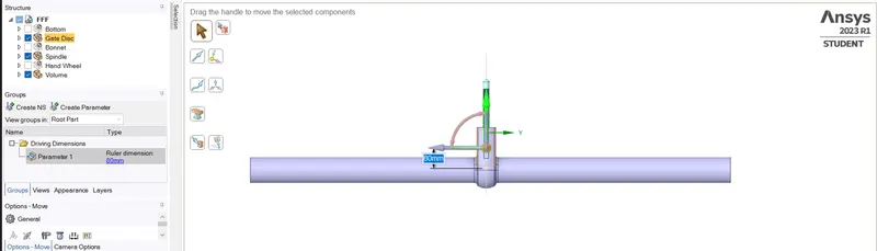
- GEOMETRY. - 10 mm(LIFT)
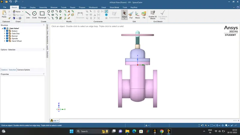
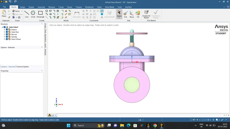
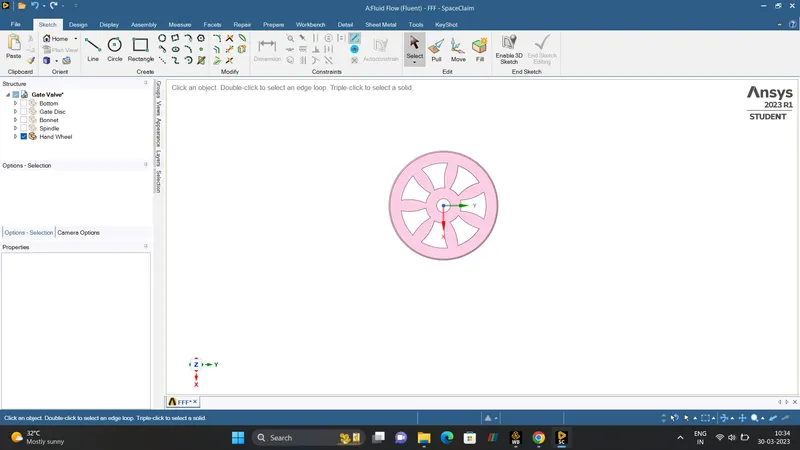
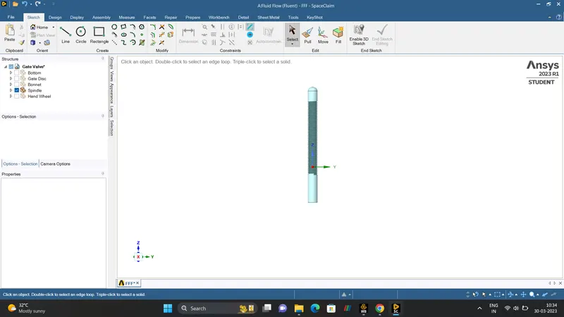
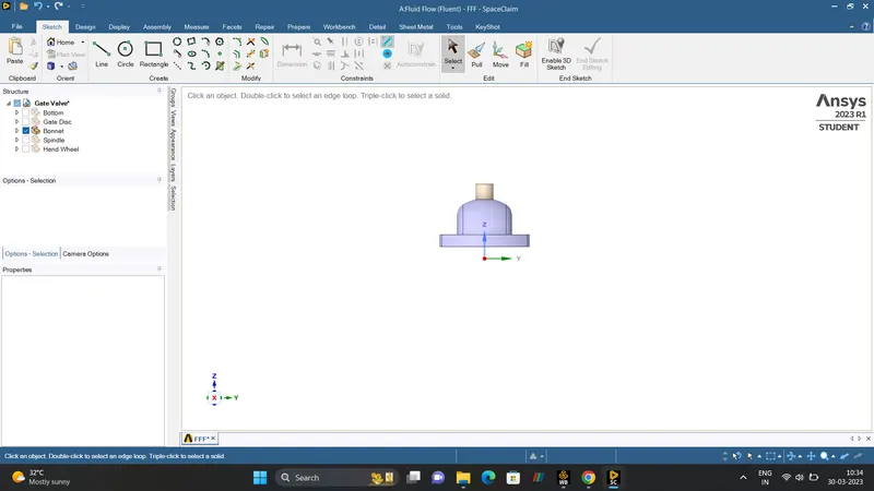
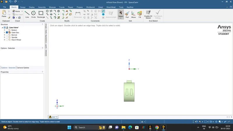
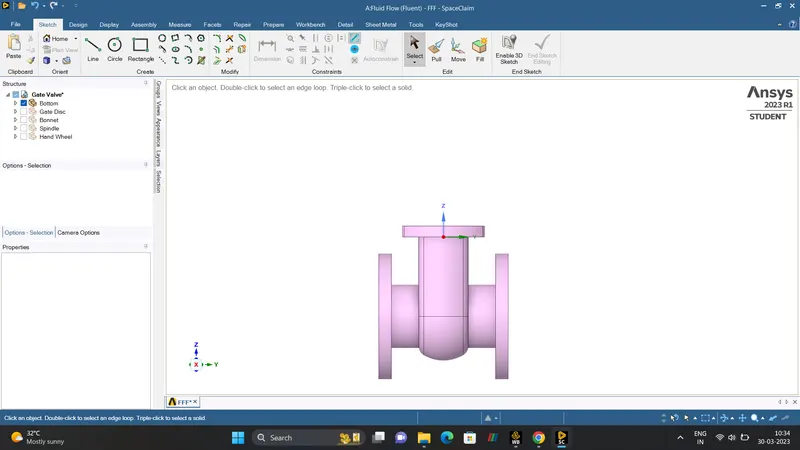
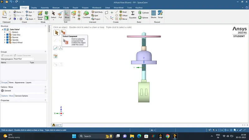
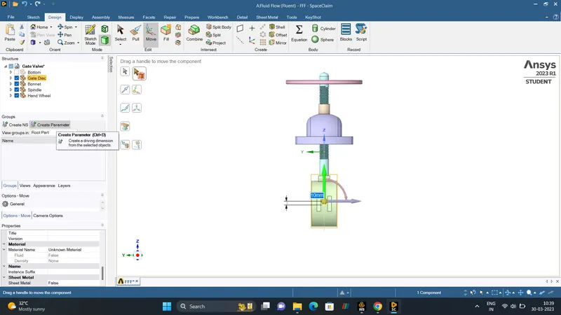
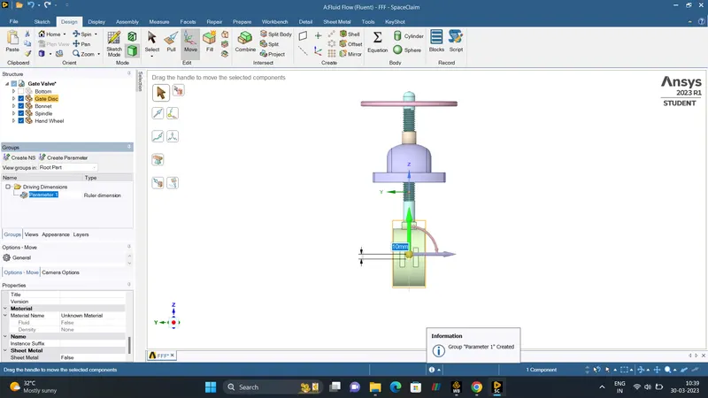
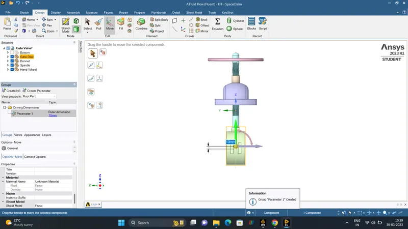
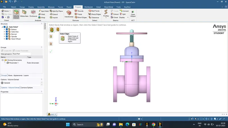
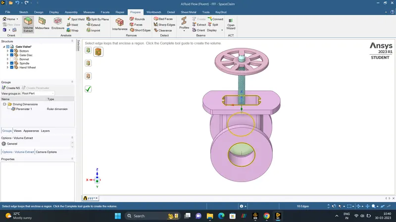
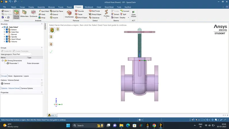
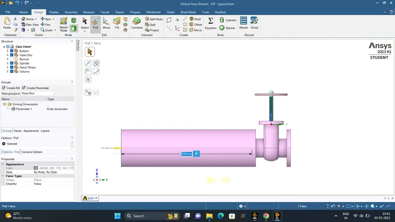
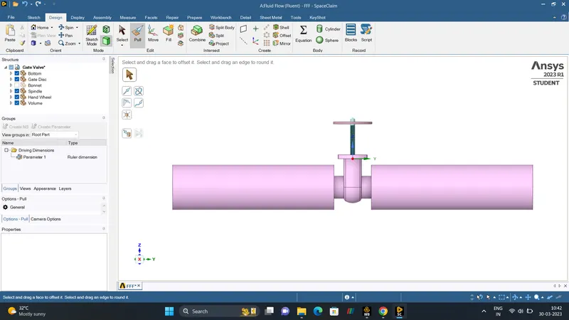
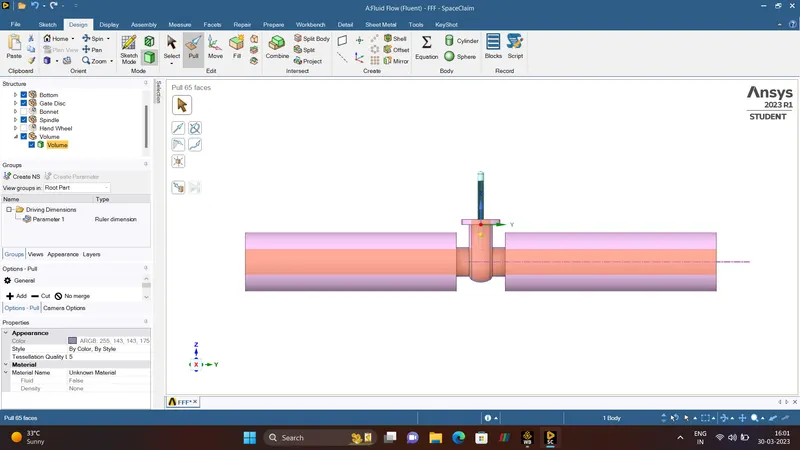
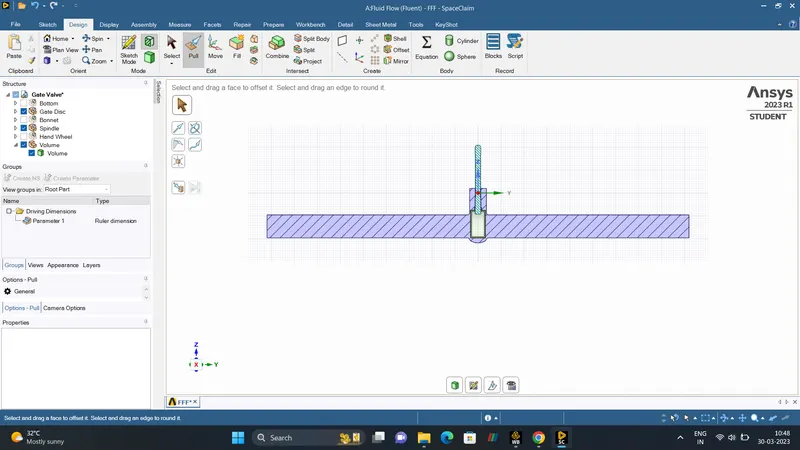
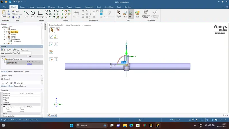
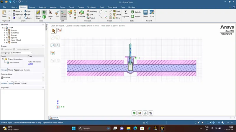
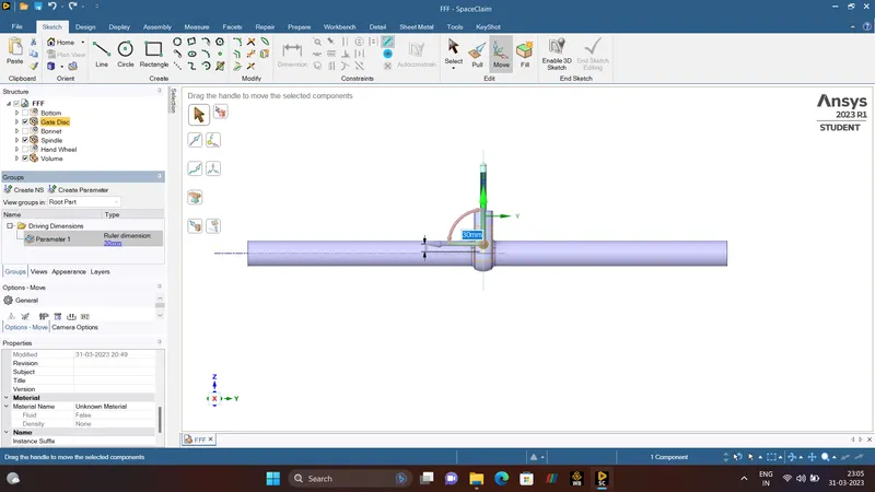
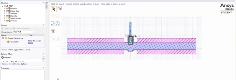
To Run a Simulation Of Parametric Study On a Gate Valve Using Ansys-Fluent. Import the CAD Model Of Gate Valve On ANSYS-SPACECLAIM. The Gate Valve Consists of Bonnet, Spindle, Gate Disc, HandWheel, Bottom. Extarct the Fluid Volume by selecting the Edges of the Bottom Circle, and Bonnent (before doing Volume Extract the Gate Disc is Lifted towards upward Direction for 10mm). The Purpose of Volume Extract is to Create a Soild based on a volume enclosed by a Single body or set of bodies. When the volume is created, the bodies used to generate the volume are temporarily Transparent. Then Hide the Geometry and Supress for PHYSICS is done, and finally the save the geometry.
- MESHING.
A Mesh is a network that is formed of cells and points. It can have almost any shape in any size and is used to solve the PDEs (Partial Differential Equation). Each cell of the mesh represent an individual solution of equation which, when combined for the whole network, results in a solution for entire mesh.
Why do we need Mesh?
Solving the entire object without dividing it into smaller pieces can be impossible because of complexity that is within the object. Holes, comes and angles can make it exteremly difficult for solvers to obtain solution. Small cells, on the other hand are comparably easy to solve and therefore preferred strategy. The PDEs is solved in each and every individuals cells. Hence each cell holds a local solution of discretised equation which is then combined together to develop a global solution.
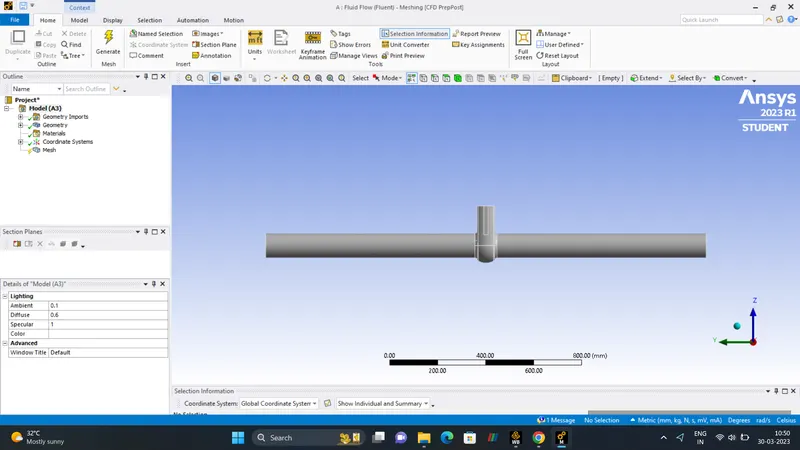
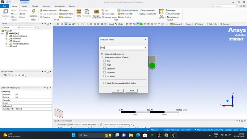
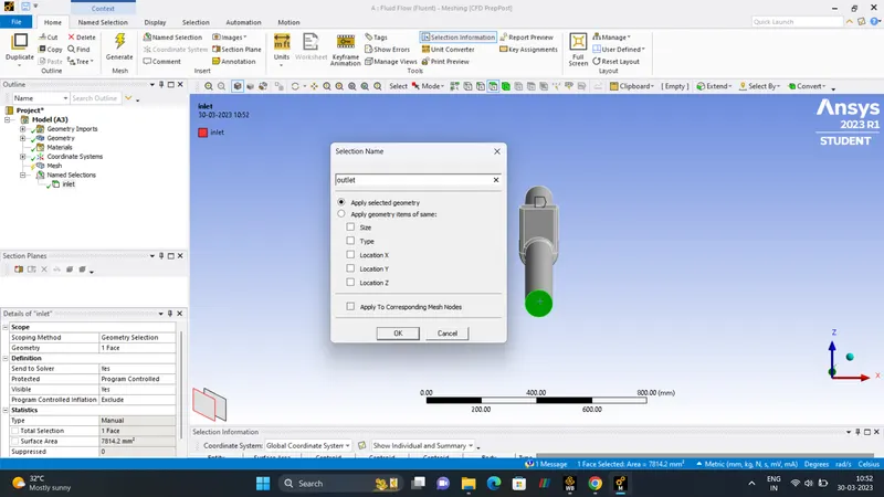
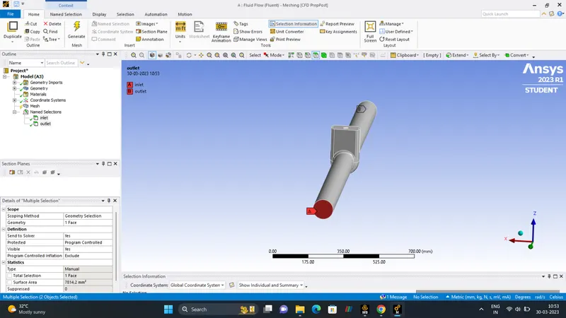
- NAME SELECTION.
INLET.
OUTLET.
- BOUNDARY-CONDITIONS
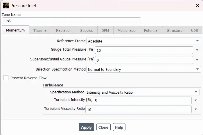
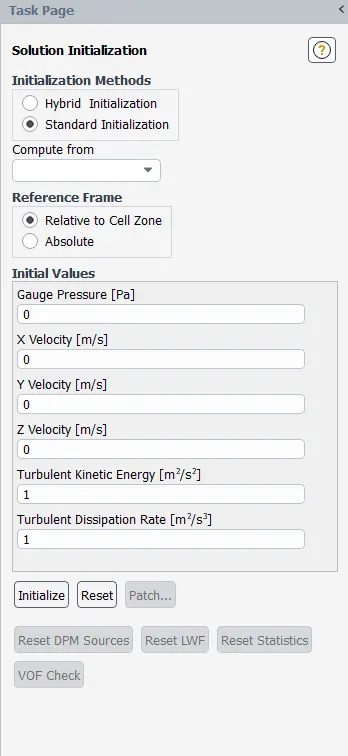
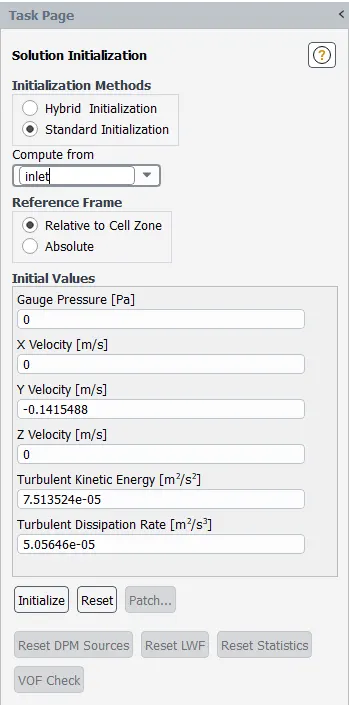
Boundary Condition pertain to the field of computational mechanics where we initialize the study with certain conditions. When we translate the problem to the computational domain, we assign different conditions to diiferent aspects of the domain. In layman's term, boundaries represent the physical bound and different components of computational domain which we initialize the study. We patch values of the certain flow properties on these boundaries, for instance it can be VELOCITY/PRESSURE/TEMPERATURE etc. Through which can start the iterative process of solving the problem.
- SETUP/ SOLVER.
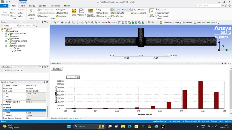
| MESH SIZE | 8mm |
| NUMBER OF ELEMENTS | 257024 |
| NUMBER OF NODES | 53008 |
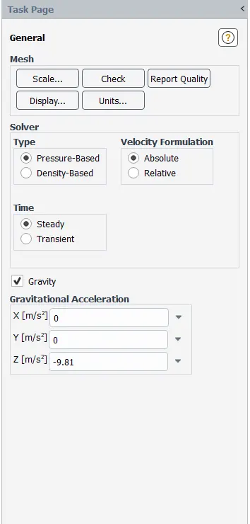
| SOLVER | PRESSURE-BASED-SOLVER |
| GRAVITY | Yes (Z-axis -9.81) |
| SIMULATION | STEADY_STATE |
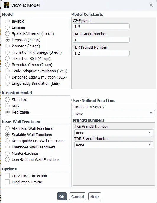
| VISCOUS MODEL | K-EPISLON `rarr`REALIZABLE `rarr`SCALABLE WALL FUNCTION |
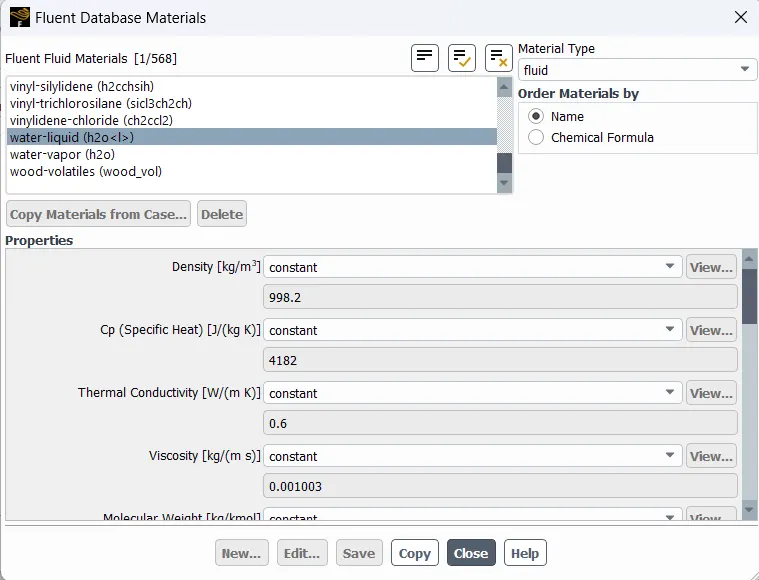
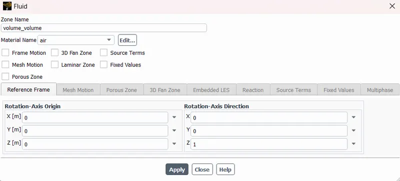
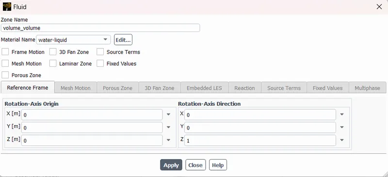
| FLUID DATA | FLUID`rarr`LIQUID`rarr`WATER (H2O) |
| INITIALISATION | HYBRID INITIALISATION |
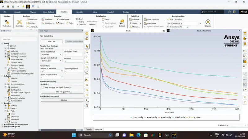
| NUMBER OF ITERATION | 300 |
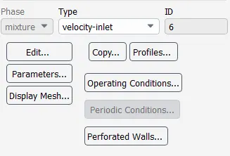
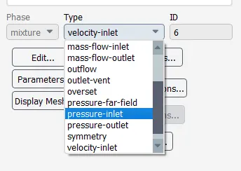
| INLET | PRESSURE-INLET. |
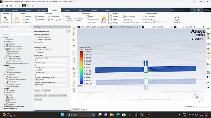
RESULTS.

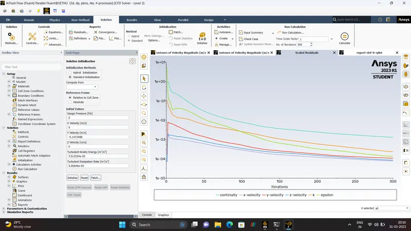
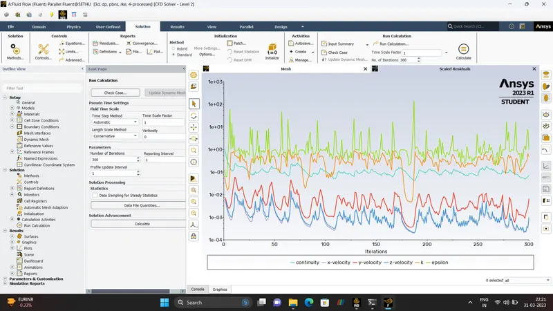
RESIDUALS
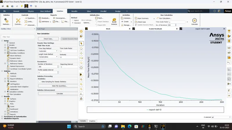
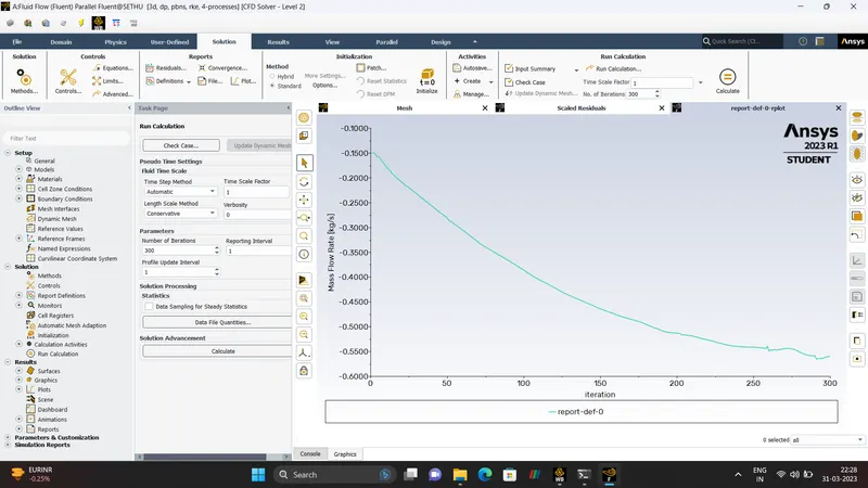
MASS FLOW RATE
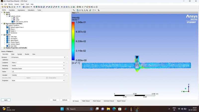
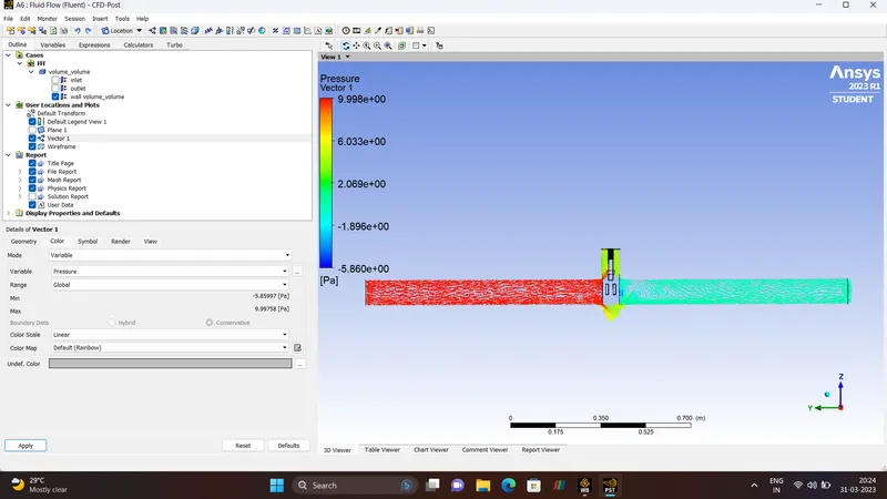
VELOCITY & PRESSURE VETCOR.
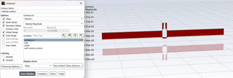
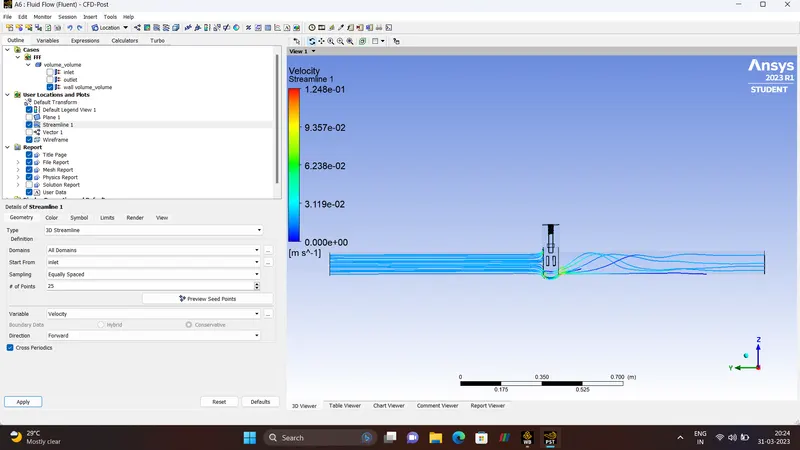
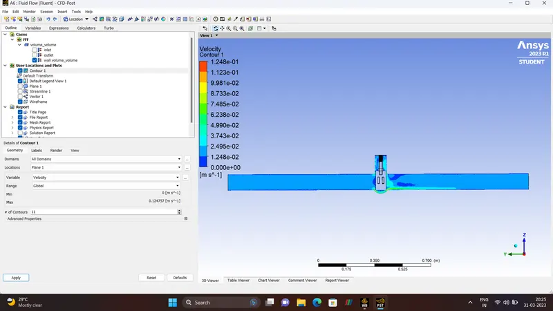
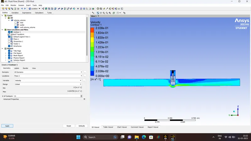
STREAMLINE & VELOCITY CONTOUR.
CASE 2 - 20 mm lift
RESIDUALS

VELOCITY CONTOUR
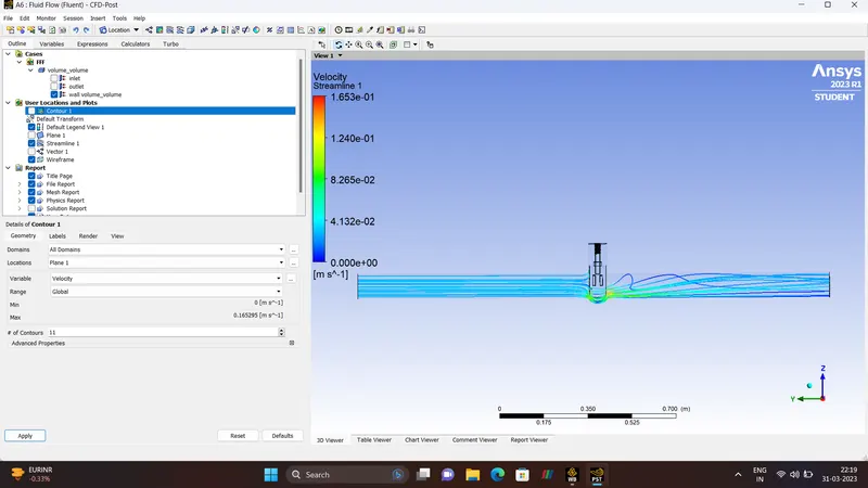
STREAMLINE
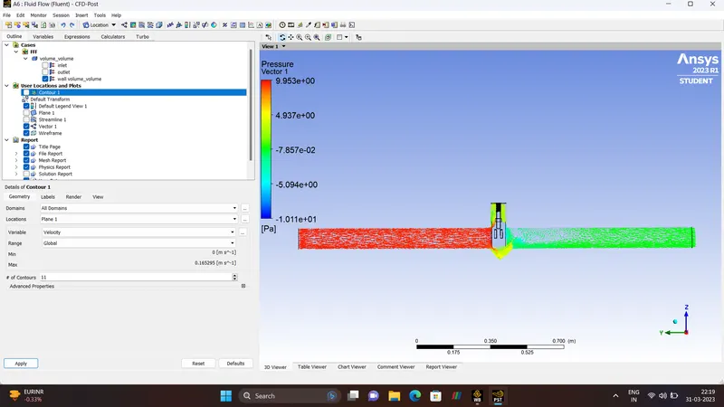
PRESSURE VECTOR
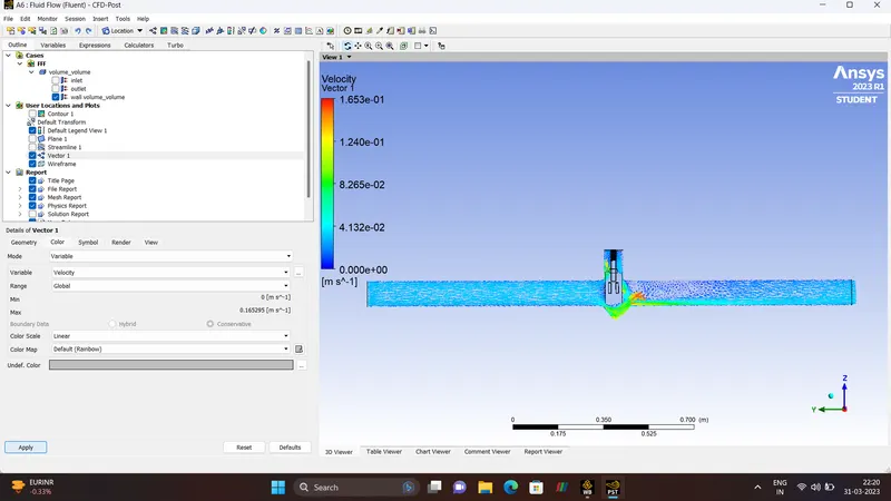
VELOCITY VECTOR
- CASE 3 - 30 mm lift
RESULTS.

VELOCITY CONTOUR.
STREAMLINE
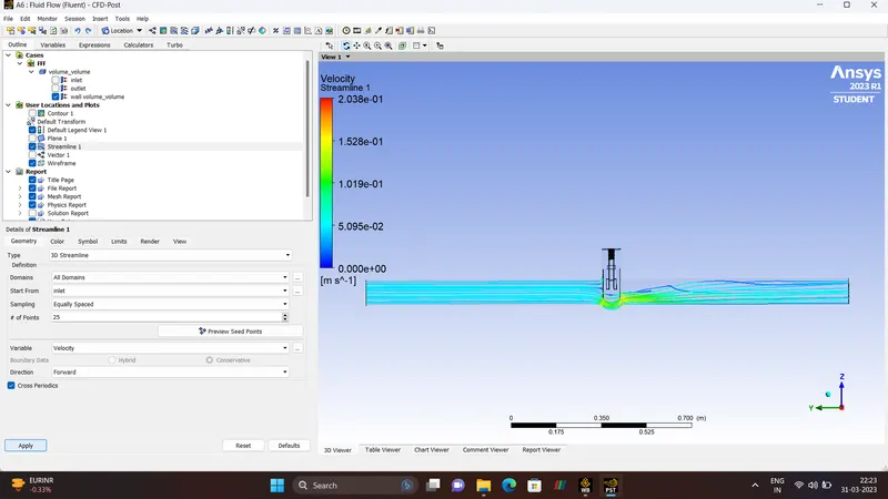
VELOCITY VECTOR
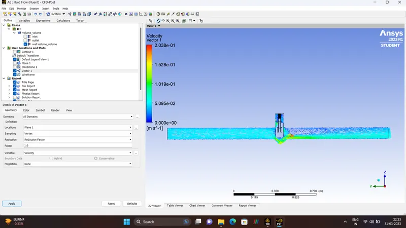
PRESSURE VECTOR
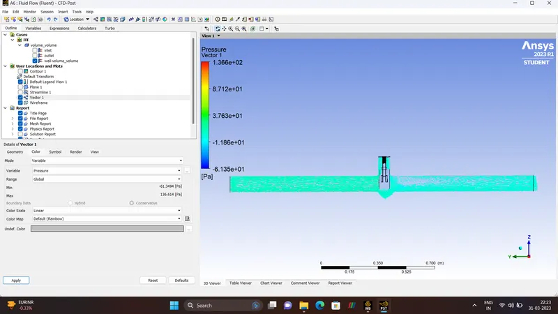
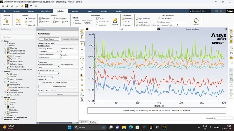
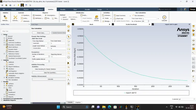
- CASE 4 - 40 mm lift
RESULTS.

PRESSURE VECTOR
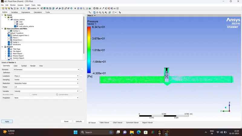
VELOCITY VECTOR
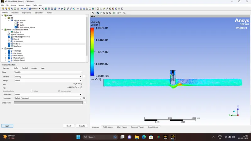
STREAMLINE
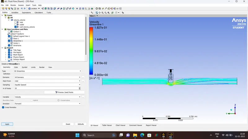
VELOCITY CONTOUR
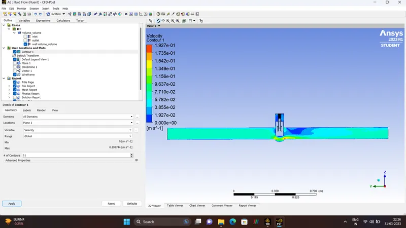
PRESSURE CONTOUR.
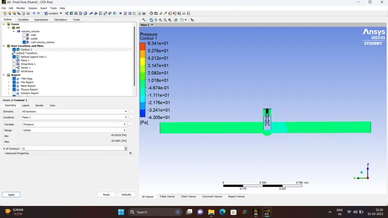
- CASE 5 - 50 mm lift
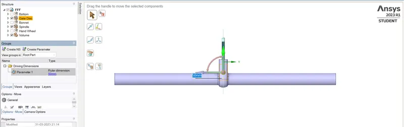
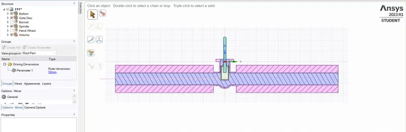
RESULTS.

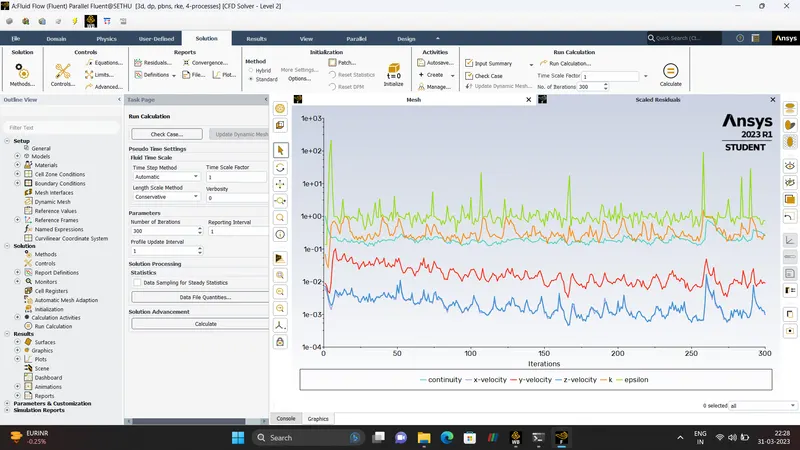
RESIDUALS.
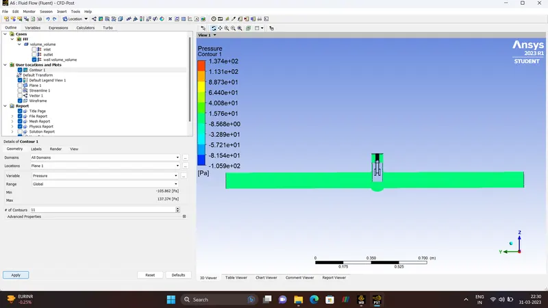
PRESSURE CONTOUR
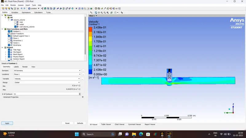
VELOCITY CONTOUR
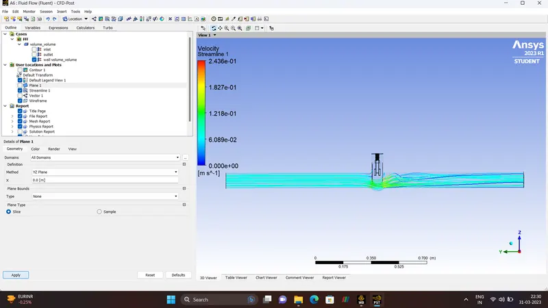
STREAMLINE
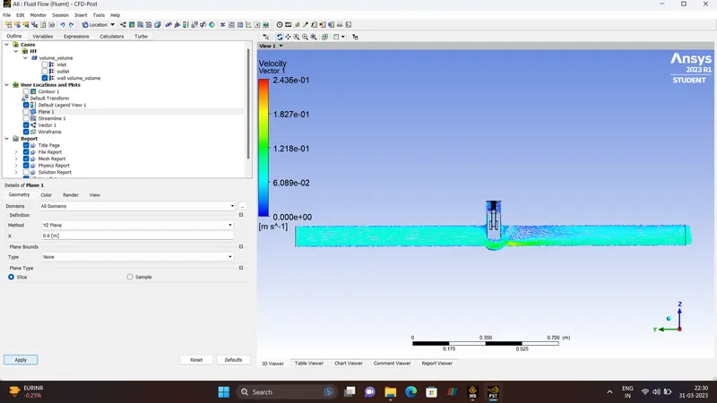
VELOCITY VECTOR
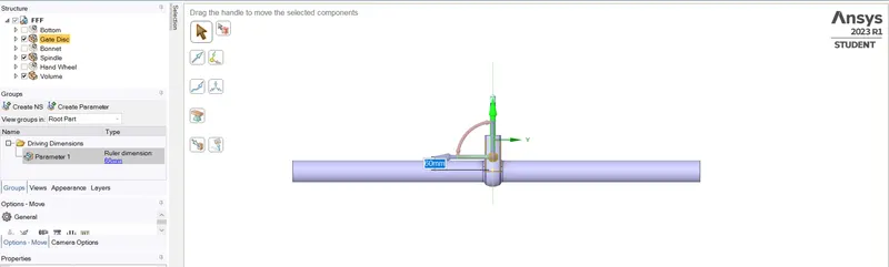
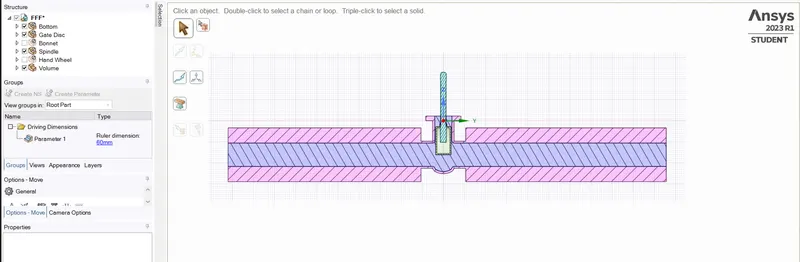
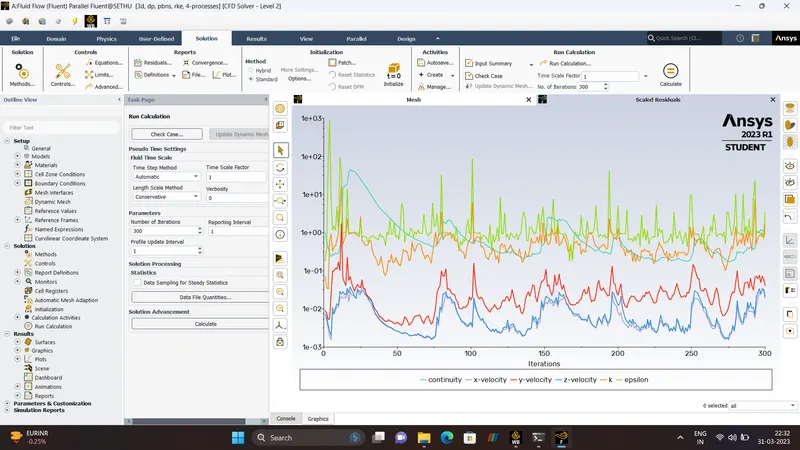
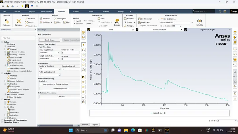
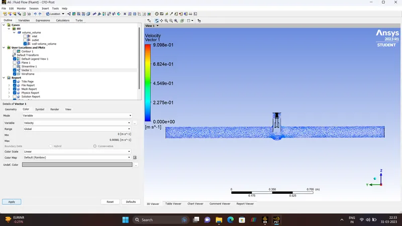
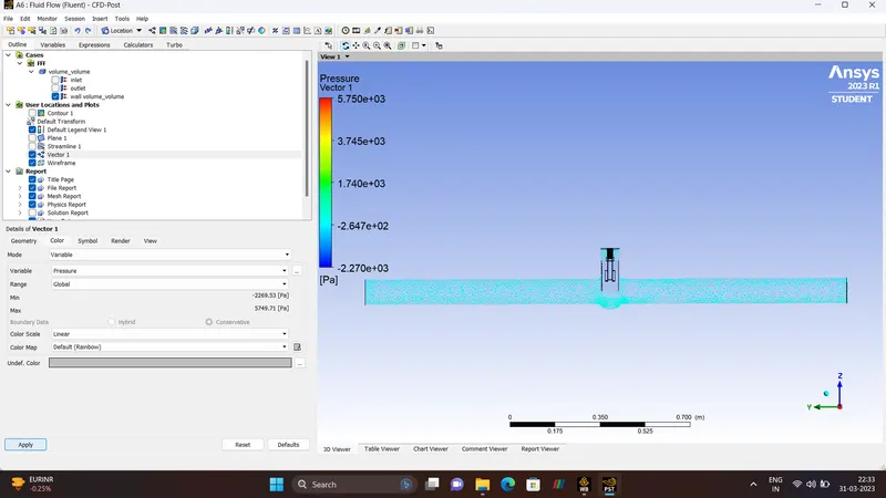
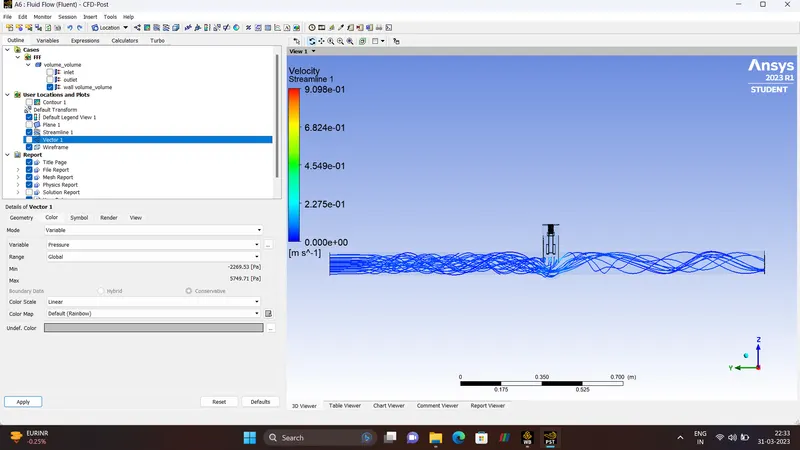
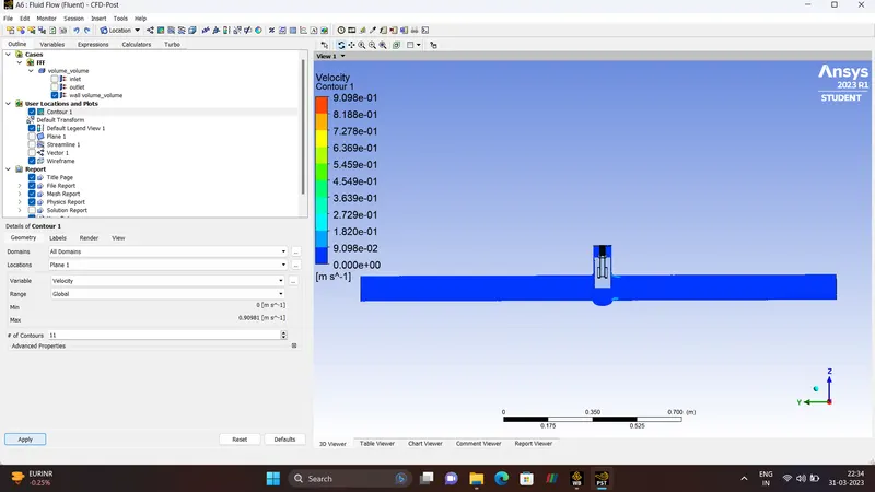
- CASE 6 - 60 mm lift
RESULTS.

VELOCITY VECTOR
PRESSURE VECTOR
STREAMLINE
VELOCITY CONTOUR
PRESSURE CONTOUR
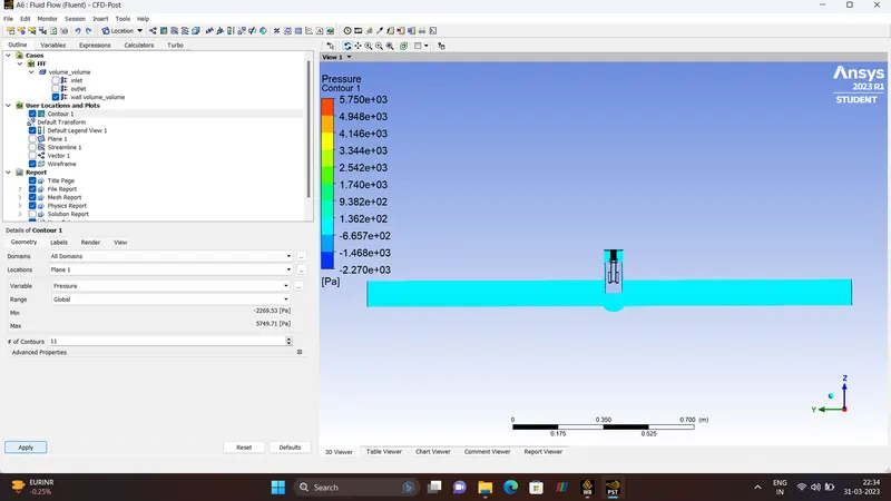
- CASE 7 - 70 mm lift
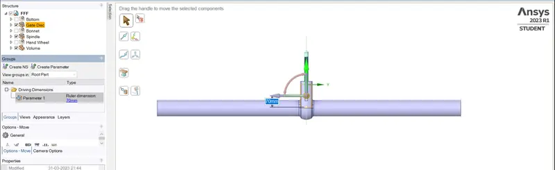
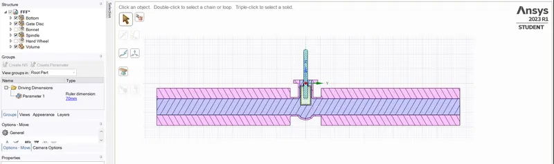
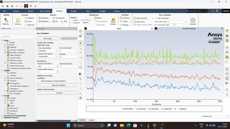
RESULTS

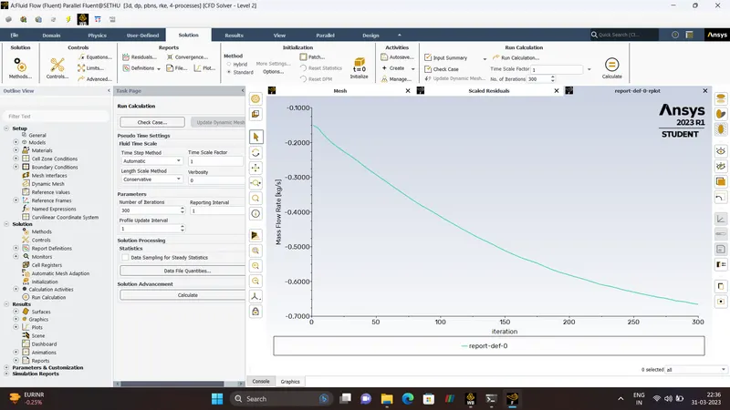
PRESSURE CONTOUR
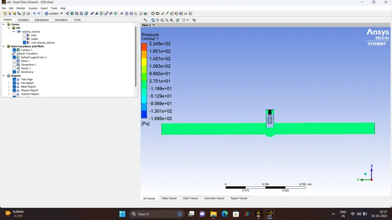
VELOCITY CONTOUR
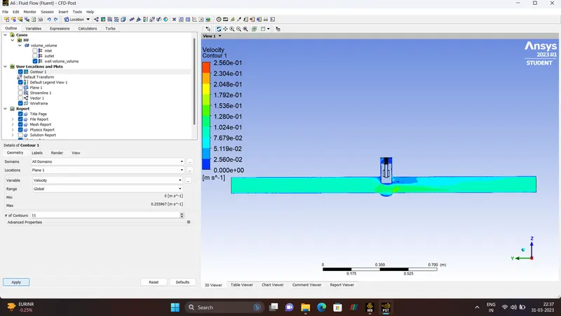
STREAMLINE

PRESSURE VECTOR
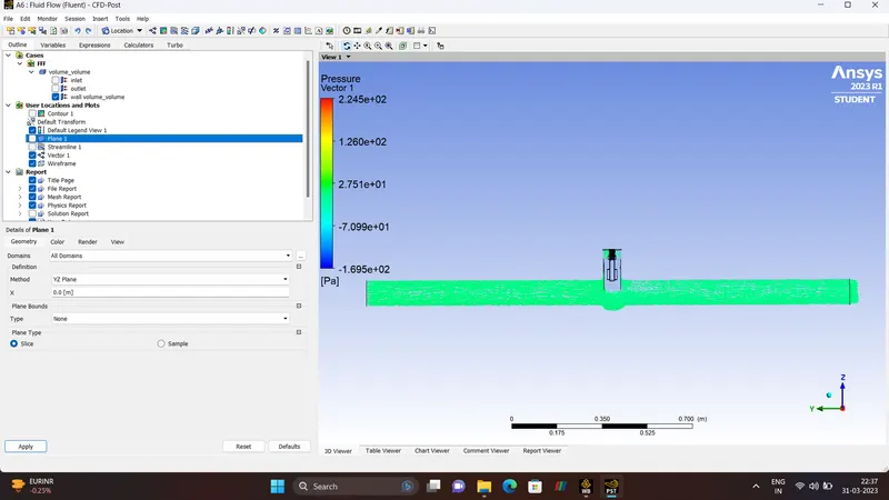
VELOCITY VECTOR
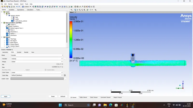
- CASE 8 - 80 mm lift
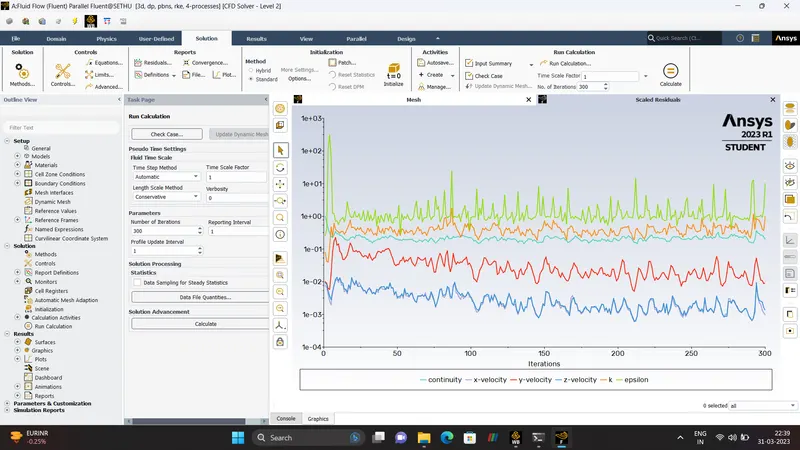
RESULTS.

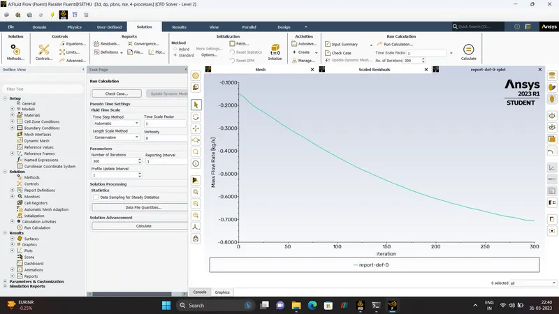
VELOCITY VECTOR
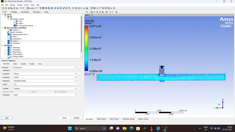
PRESSURE VECTOR
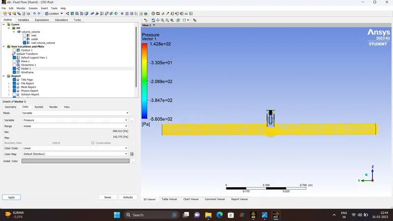
STREAMLINE
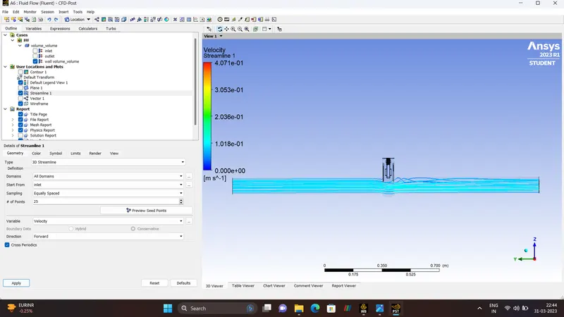
VELOCITY CONTOUR
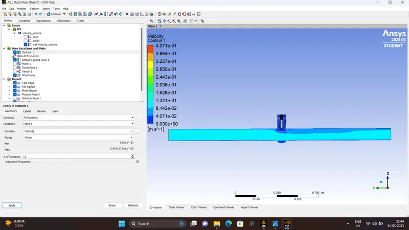
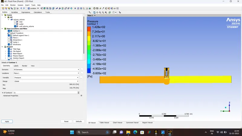
PRESSURE CONTOUR
ANIMATION
We Can be to see the Difference between the 10mm and 80 mm lift,
80 mm lift
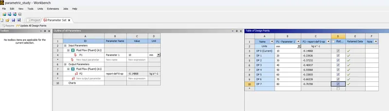
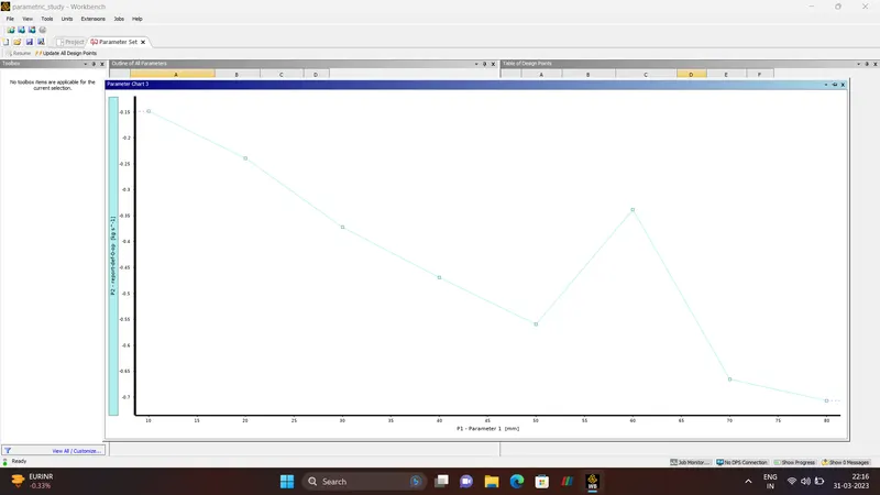
- PARAMETRIC STUDY.
- FLOW CO-EFFICIENT.
The Flow Co-efficient of a device is a relative measure of its efficiency at allowing fluid flow. It describes the relationship between the pressure drop across an valve or other assembly and the corresponding flow rate.
Mathematically the flow co-efficient Cv can be expressed as
`C_v rarr Q sqrt(SG)/sqrt(DeltaP)`
Where,
Q - Rate Of Flow.
SG - Specific Gravity Of the Fluid
`Delta P` Pressure Drop across the Valve.
- FLOW FACTOR.
The Metric Equivalent flow factor(Kv) is calculated using Metric Unit.
`k_v rarr Q sqrt(SG)/sqrt(DeltaP)`
where,
kv - the flow factor.
Q - flow rate
SG - Specific gravity of the fluid.
`Delta P`Differential pressure across the device.
kv can be calculated from Cv
`k_v rarr 0.865 *C_v`
Calculation For Flow Factor and Flow Co-efficient.
10 mm lift.
Q - 0.14868
SG - 1
`Delta P`- 10
`C_v rarr 0.14868 * sqrt 1/sqrt10`
`C_v rarr 0.14868 * 0.31622776601`
`C_v rarr 0.04701674425`
Flow Factor
`k_v rarr 0.865 *0.04701674425`
`k_v rarr 0.04066948377`
20 mm lift
Q - 0.23926
`C_v rarr 0.23926 * 0.316227`
`C_v rarr 0.07566047202`
`k_v rarr 0.06544630829`
30 mm lift
`C_v rarr 0.37232*0.316227 rarr 0.11773763664`
`k_v rarr 0.865*0.11773763664 rarr0.10184305569`
40 mm lift
`C_v rarr 0.14842746699`
`k_v rarr 0.12838975894`
50 mm lift
`C_v rarr 0.17698592736`
`k_v rarr 0.15309282716`
60 mm lift
`C_v rarr 0.10705865085`
`k_v rarr 0.09260573298`
70 mm lift
`C_v rarr 0.21041428353`
`k_v rarr 0.18200835525`
80 mm lift
`C_v rarr 0.22359778716`
`k_v rarr 0.19341208589`
- CONCLUSION
Hence, We can conclude from the results Parametric Study on the a GATE VALVE is Simulated and the Solution is Converged.
Whenever the Gate disc Valve is lifted towards the upward direction the Mass-Flow-Rate Increases.