Week 3 Challenge : CFD meshing on Turbocharger
- AIM.
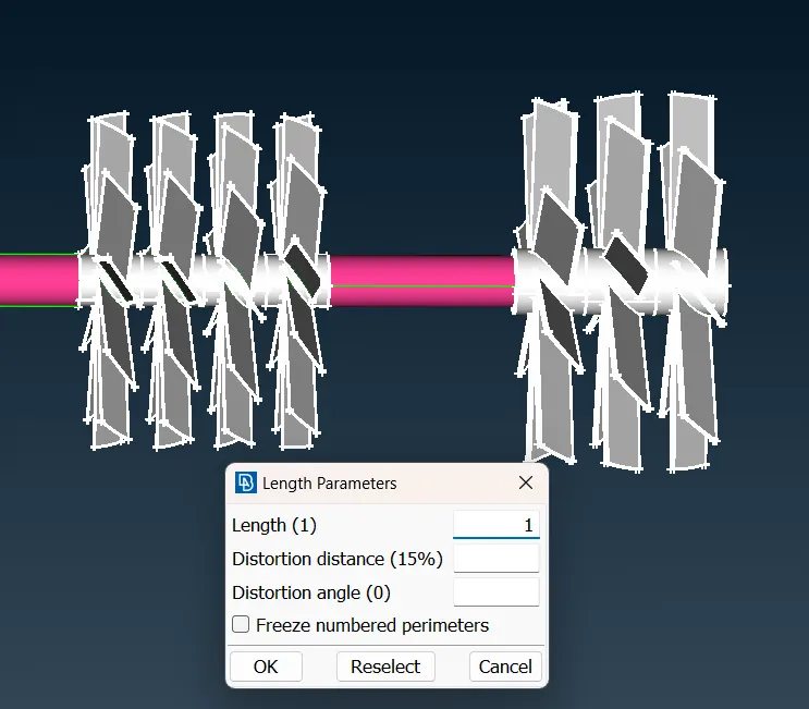
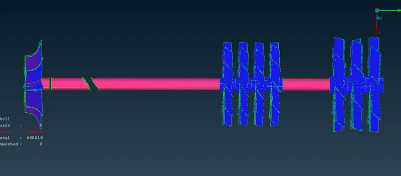
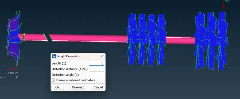
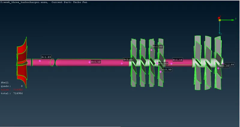
To Study and perform a SURFACE MESHING on a TURBOCHARGER using ANSA.
- OBJECTIVES.
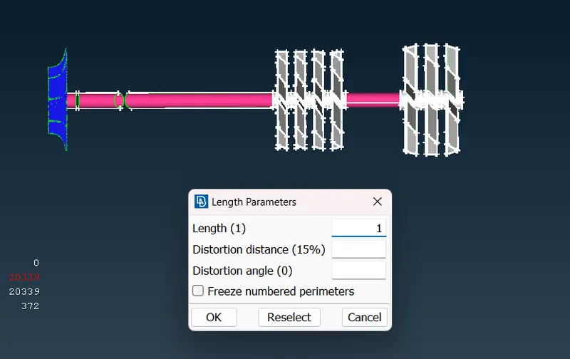
- Blade stage_1 = 1 mm
- Blade stage_2 = 1 mm
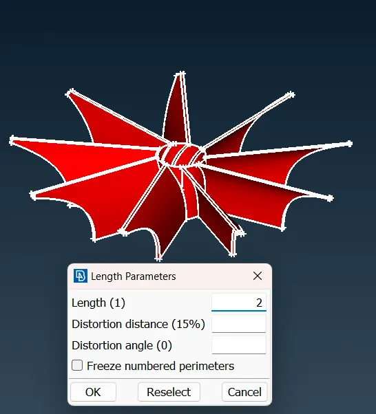
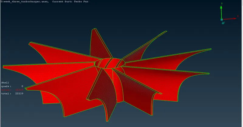
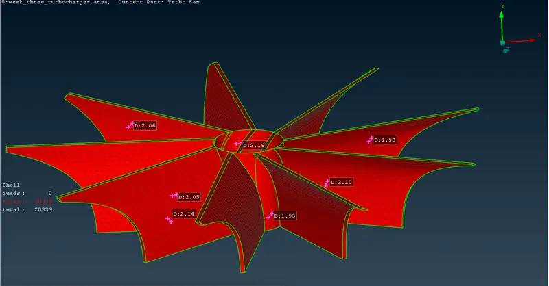
- Impeller = 2 mm
- Shaft rotor = 1 mm
- Turbo casing = 5 mm
- Compressor casing = 5 mm
- Inlet casing cover = 5 mm
To Write a detailed report on your surface meshing & Volume meshing process.
- PROCEDURE.
TURBOCHARGER.
A Turbocharger is a Turbine-Driven device which is used to increase the Volumetric Efficiency of an Internal Combustion Engine. It takes power from the exhaust gases coming from an engine and use that to suck fresh air from the atomsphere and supply it to the engine for combustion.
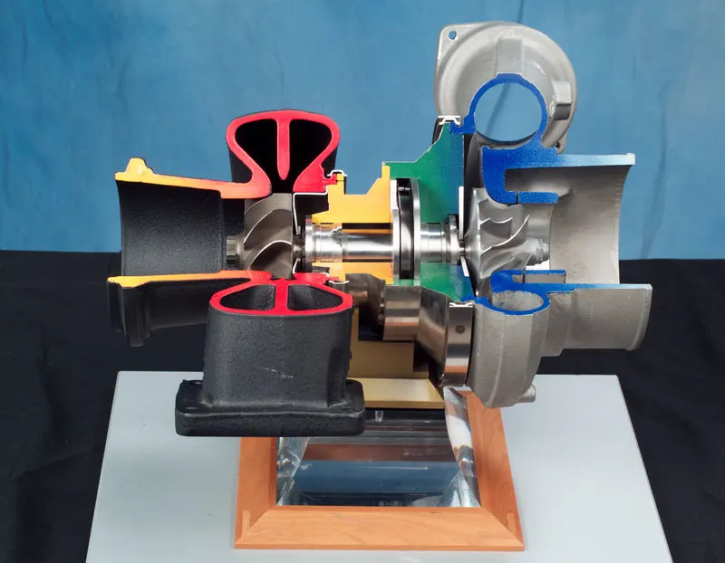
Turbocharger components are classified as,
TURBINE.
COMPRESSOR.
CENTRAL HOUSING HUB.
- TURBINE.
The Turbocharger Turbine, which consists of a turbine wheel, and turbine housing, converts the engine exhaust gas into mechanical energy to drive the compressor. The gas, which is restricted by the turbine's flow cross-sectional area results in Pressure and Temperature Drop between the Inlet and Outlet. This Pressure Drop is coverted by turbine into kinetic energy to the turbine wheel. There are two main Turbine types,
AXIAL FLOW TYPE.
RADIAL FLOW TYPE.
AXIAL-FLOW TYPE - The Flow through the wheel is only in the axial direction.
RADIAL FLOW TYPE - Gas inflow is centripetal, that is in a radial direction from the outside in, and gas outflow in a axial direction.
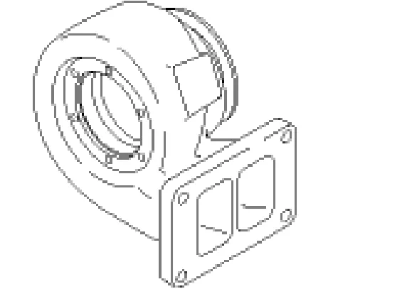
- TURBINE HOUSING.
Turbine Housings are manufactured in various grades of spheroid graphite iron to deal with thermal fatigue and wheel brust containment.
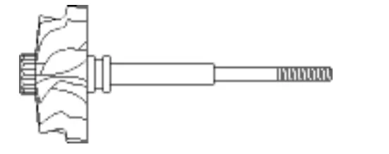
- TURBINE WHEEL.
The Turbine Wheel is housed in the turbine casting and is connected to a shaft that in turn rotates the compressor wheel.
- COMPRESSOR.
Turbocharger compressor are generally centrifugal compressors consisting of three essential components, COMPRESSOR WHEEL, COMPRESSOR HOUSING, COMPRESOR DIFFUSER. With the Rotational Speed of the Wheel, air is drawn in axially, accelerated to High Velocity and then expelled in the radial direction.
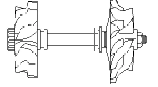
- COMPRESSOR WHEEL.
Compressor impellers are produced using a variant of aluminum investment Casting process.
- COMPRESSOR COVER.
Compressor Housing are also made in cast aluminum.
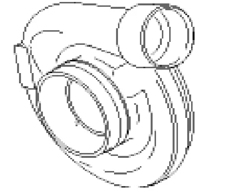
- CENTRAL HOUSING HUB.
The Central housing Hub is Shaft which connects the Turbine and Compressor to boost the performance of the engine. The Size of the Turbine, Compressor Wheels, and the Size of their housing affect the turbo's dynamic range. Hence the choice is made according to the requirement.
- WORKING PRINCIPLE OF TURBOCHARGERS.
Exhaust gases from the engine flow along the exhaust maniflod and through nozzle box assmebly and enters into the BLADES of the gas turbine where the mechanical work is done by the gas turbine. As the turbine turns at High Speed, It causes the compressor to compressor the atomspheric air incase of diesel engine or air fuel mixture in case of the petrol engine and enters the engine cylinder.
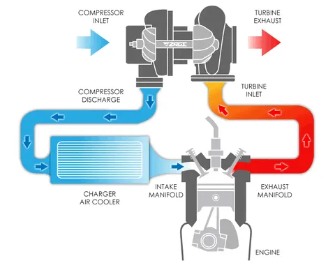
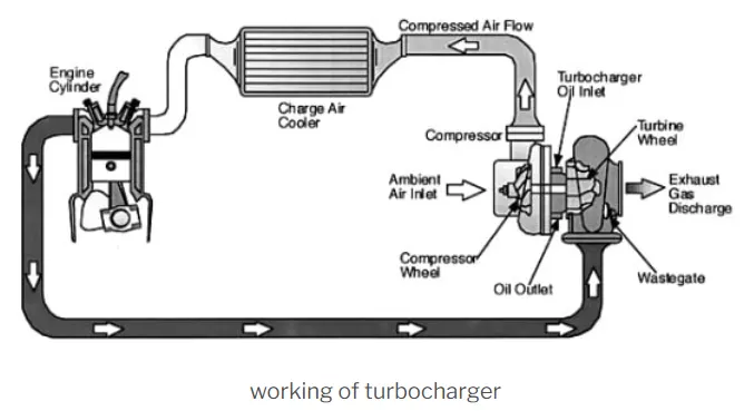
In both systems, air enters through an air intake, passes through an air cleaner, and travels through a duct (usually funnel shaped) to the compresor inlet portion of the turbocharger. From there air is forced through a diffuser into the intake manifloed, to the inidividual cylinders. The most critical problem is controlling the manifold.
This is the amount the pressure created by the turbocharger. The engine will begin to detonate and eventually burn holes in the pistons and self destruct. The solution lies in the safety valve which is keyed to intake manifold pressure, exhaust pressure or a combined of both. At a predetermined pressure, the safety valve will open, allowing some of the exhaust gas to pass directly into exhaust system bypassing the turbocharger. This Keeps the intake manifold pressure maximum.
The Turbocharger itself spins at a maximum Speed of about 110,000 rpm at highway speeds and is capable of supplying boost pressure of up to 60-70 psi (413 - 483 Kpa) on a professional racing engines.
- ADVANTAGES.
Improved horse-power in the case of both Petrol and Diesel Engines.
The Engine runs Smoother and quieter.
Less smoke during low speed accleration.
- DISADVANTAGES.
Entails better cooling system.
Design becomes expensive and complicated.
Wear and Tear is at a faster rate.
- GEOMETRY
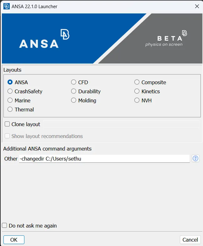
ANSA is a Computer Aided-Engineering tool for Finite Element Analysis and Computational Fluid Dynamic Analysis widely used in the Automotive Industries. It is developed by BETA CAE Systems.
- LAYOUT.
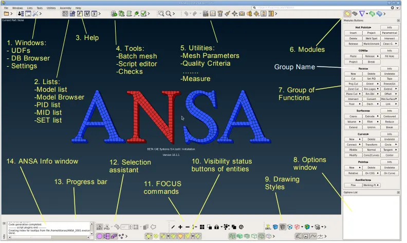
- GEOMETRY.
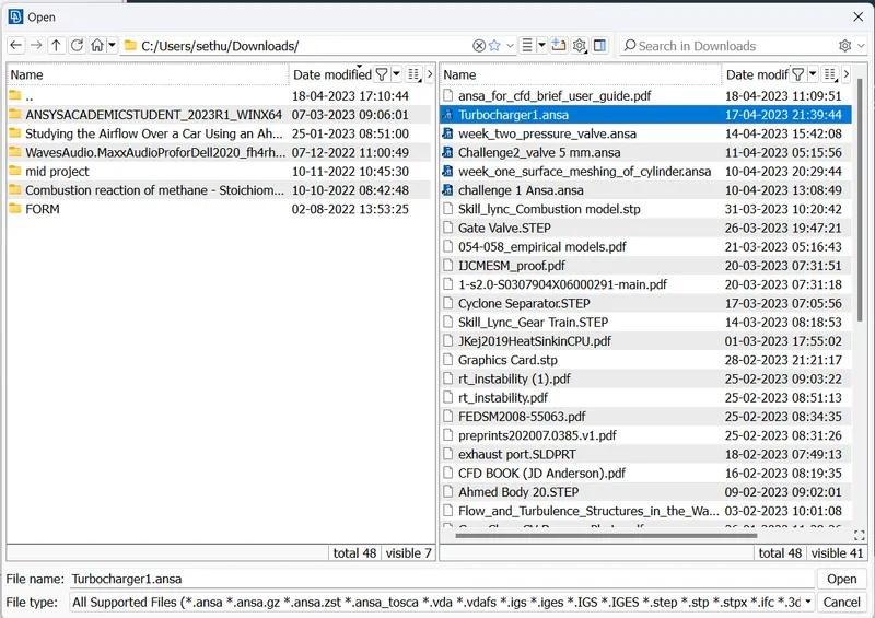
To do a Surface Meshing on a TURBOCHARGER, First Step is to Import the CAD model Of a Turbocharger on a ANSA Spaceclaim. Once the CAD model is imported in the ANSA, most important step is to check the SINGLE CONS. Whenever the Single Cons is present topo-clean needs to done.
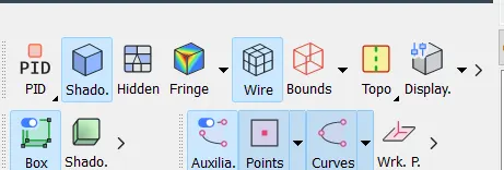
TOPO CLEAN-UP →">→→ Sets up tools for Geometry Clean up and then setting up the PIDs.
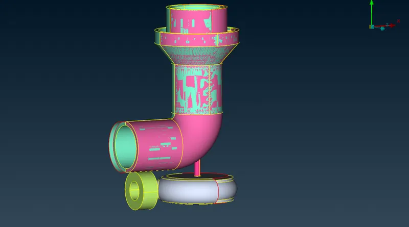
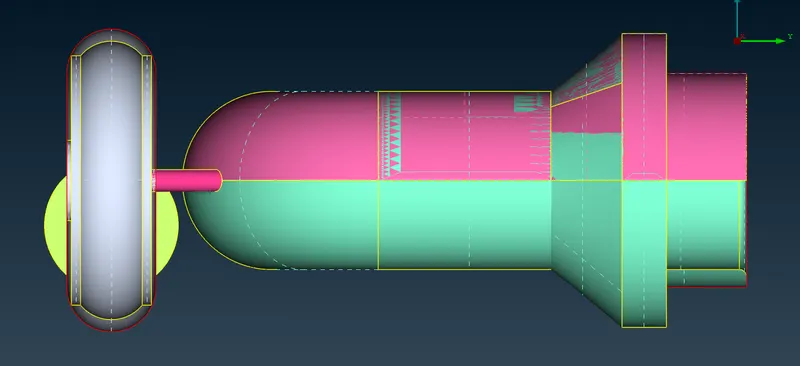
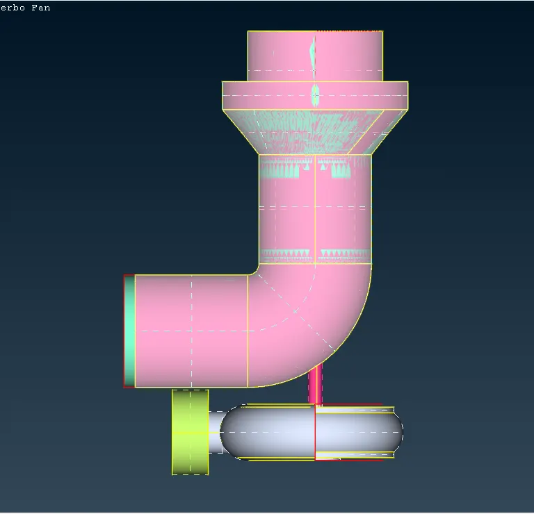
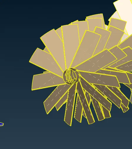
In CAD model of the Turbocharger, We can clearly able to see the Missing Surfaces, OVER-LAPPING surfaces also present, need to get rid of it, and in the drawing styles name ENTITIES into PIDs.

- SINGLE CONS.
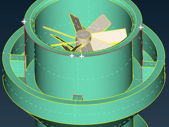
The edges in ANSA is called as CONs. Single cons are highlighted in the Red Color, Double Cons are in Yellow color. Triple Cons in Blue Color.
- CROSS-HATCH.
This allows the visualisation of Green lines along the center isoparameteries of the faces. Cross-hatch also used to select the green lines.
- COMMANDS.
|
OR →">→→ OR is used to Isolate the Surfaces. AND→">→→ It is Used to retrive the Connected Surface. NOT→">→→ NOT is similar to OR which is used to isolate the Surface but, need to double click the surfaces. ALL →">→→ ALL is used to retrive the all the hidden Surfaces of the Geometry. LOCK→">→→ LOCK is used to lock the Present Geometry. PID →">→→ PID is a Property ID which is Used to set the Boundary Conditions in the CFD. ENT →">→→ ENTITIES refers to Face, POINT, Curves, MESH ELEMENTS, etc. |
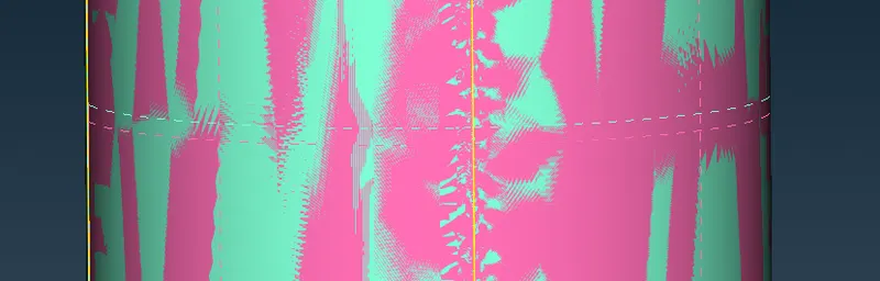
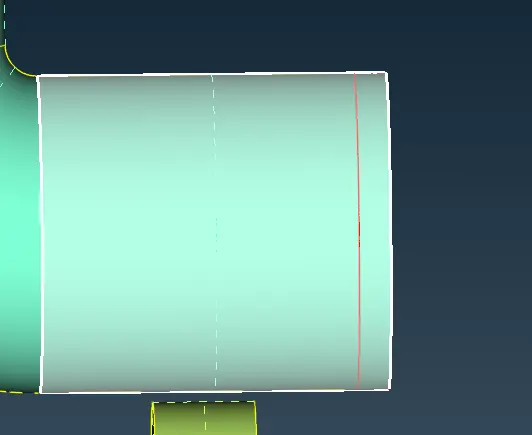
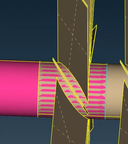
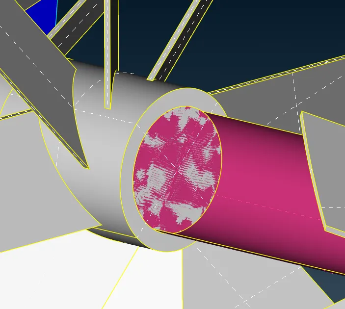
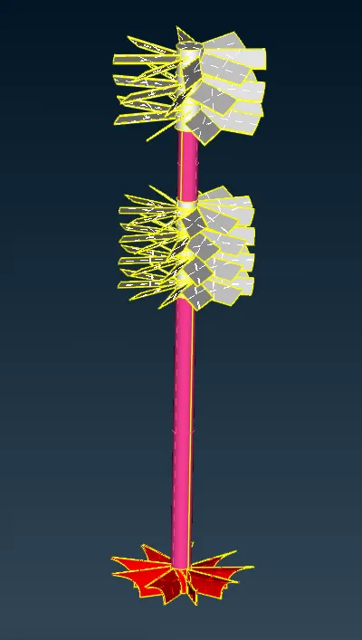
To Delete the PINK Colour Glitching Surfaces need to delete the pink CROSS-HATCH which is present over there. After deleting the Over lapping surfaces, we need to fix the missing Surfaces of a turbocharger.
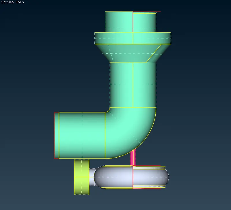
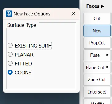
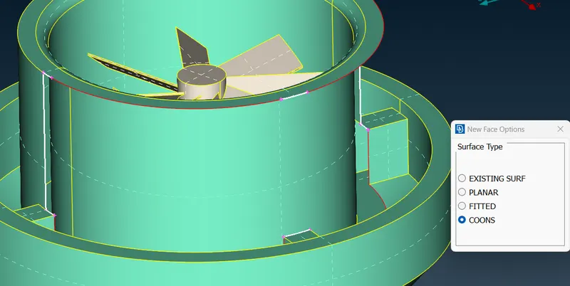
There are Four Types of FACES.
EXISTING SURFACE
PLANAR
FITTED
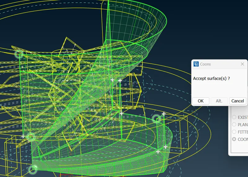
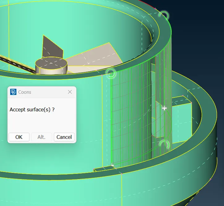
COONS

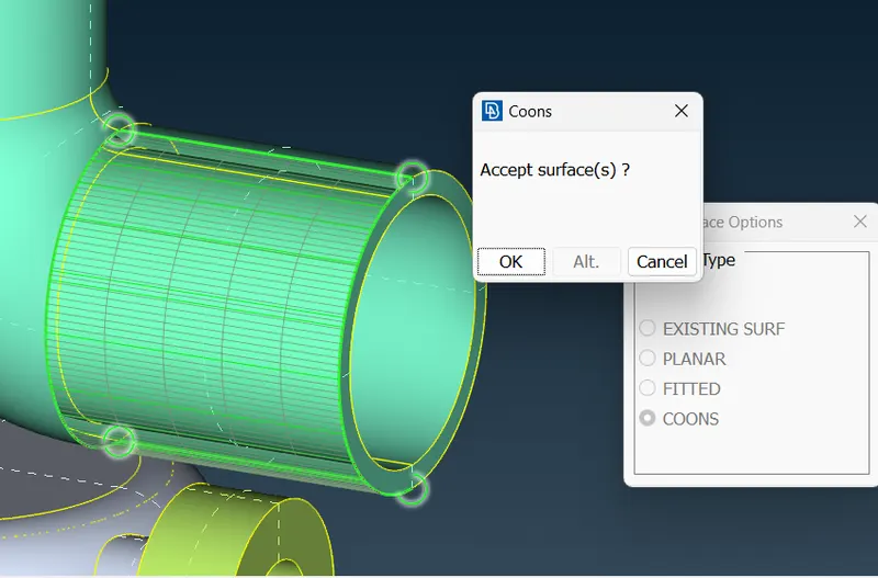
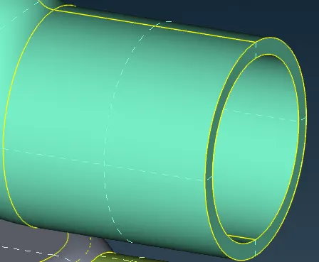
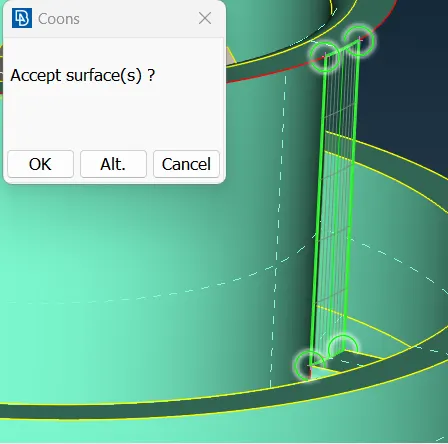
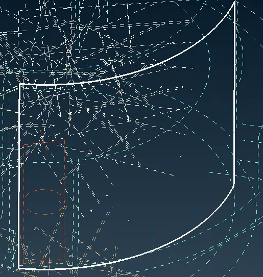
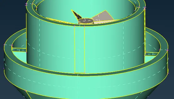
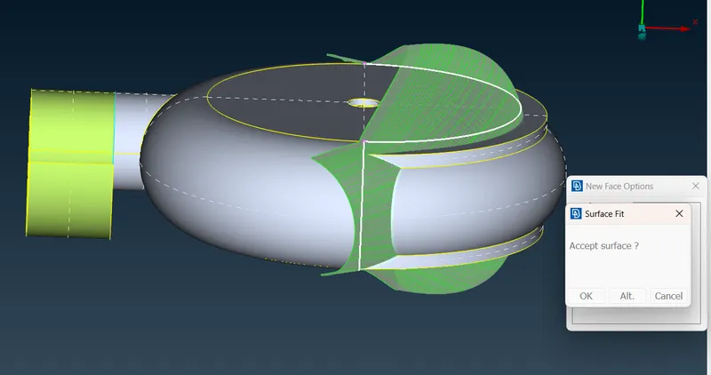
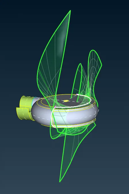
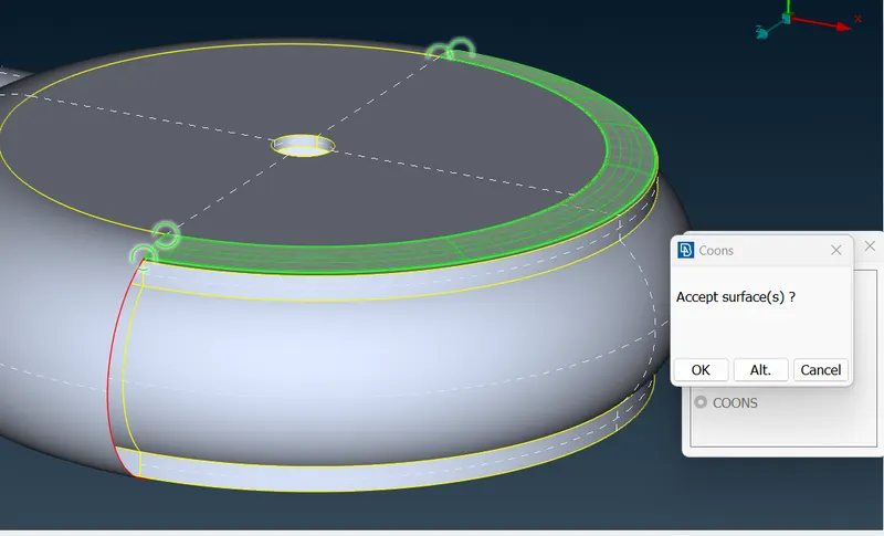
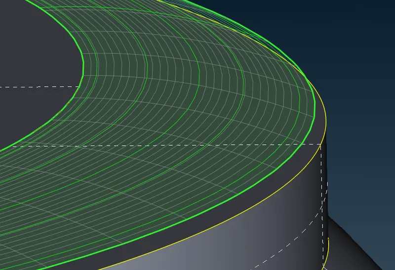
While Using COONS options to fix the missing region on Top Surface of a COMPRESSOR CASING, The COONS or FITTED could'nt able to fix that the error. So in such cases the HOTPOINT is used to Point the surfaces and then COONS is used to fix the mixing region.
- SINGLE CONS.
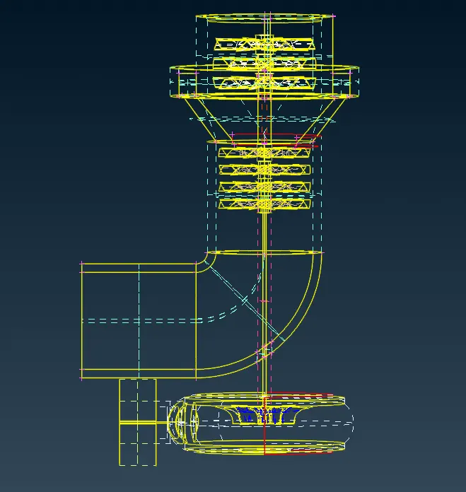
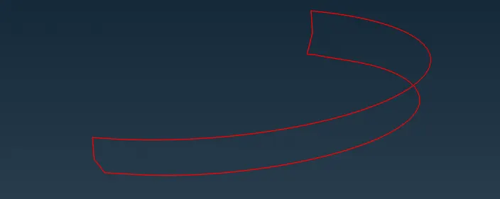
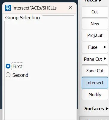
In this Case, INTERSECT command is used to Intereaction between the surfaces, after being intersected delete the unwanted surfaces.
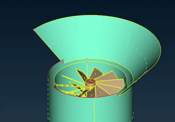
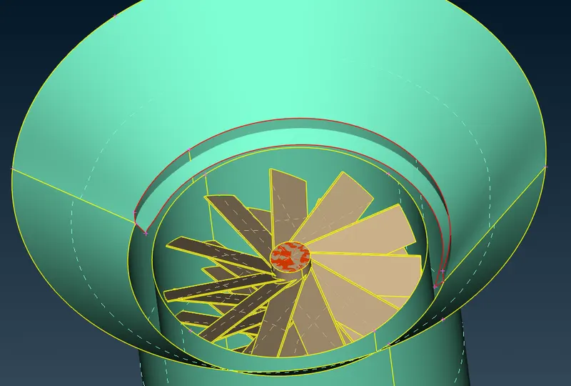
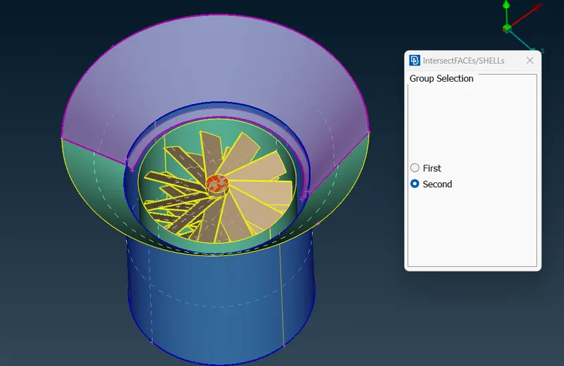
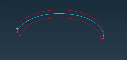
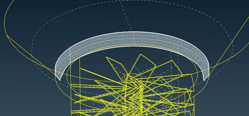
There are two methods to fill the TURBO CASING.
- METHOD ONE.
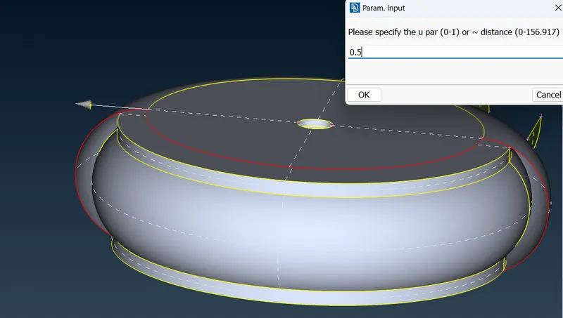
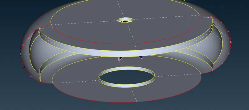
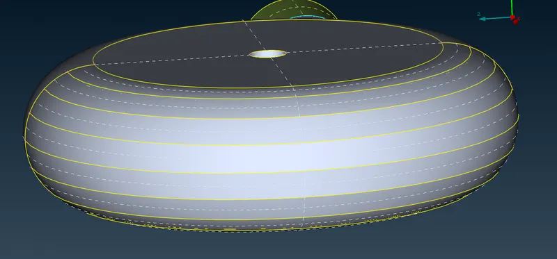
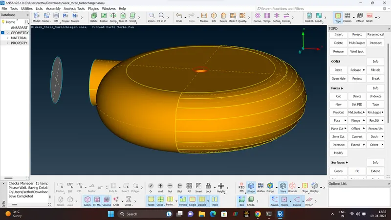
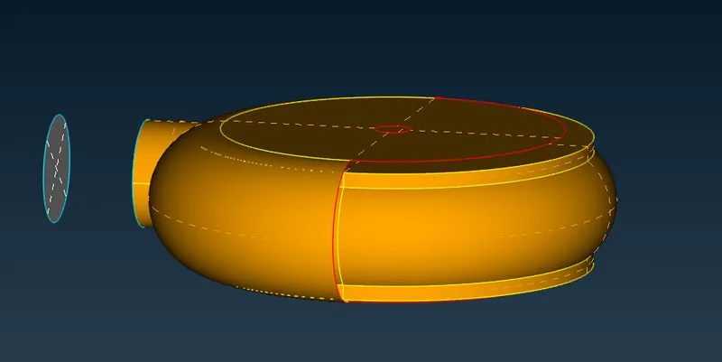
When we try to fill the TURBO CASING, with the fill hole command, errors been occured, to overcome the errors, HOTPOINTS needs to be created in order to create the hotpoint, parametrical inputis beebn assign (0.5). Then COONS command is used to fill the holes.
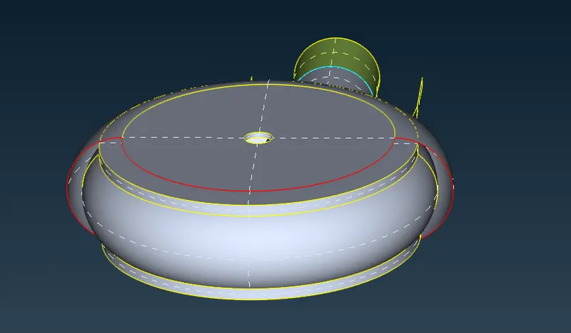
- FINAL GEOMETRY.
- SECOND METHOD
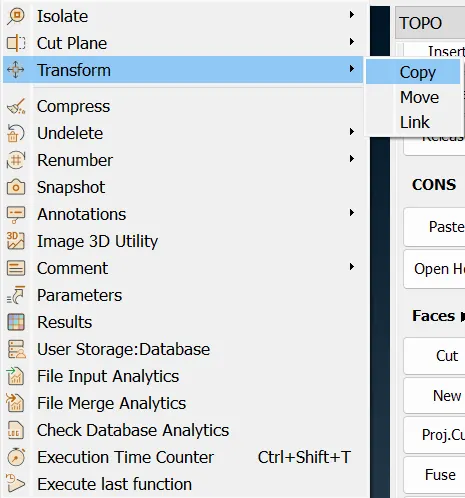
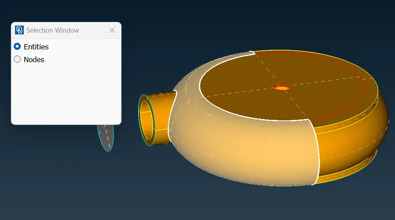
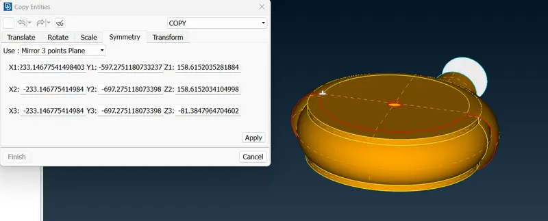
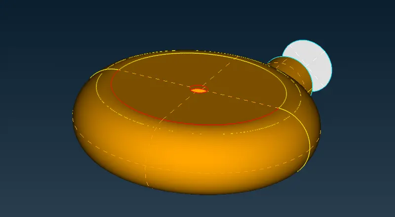
Second Method is easy compare to the method one, with the help of TRANSFORM select the entites and do the 3 point mirror. This method takes less time than the method one and There is a Smooth Surface, where else in method one lines are formed. Regarding the Single cons, just click the topo and select the region will form a Double cons Respectively.

- GEOMETRY CHECK-UP
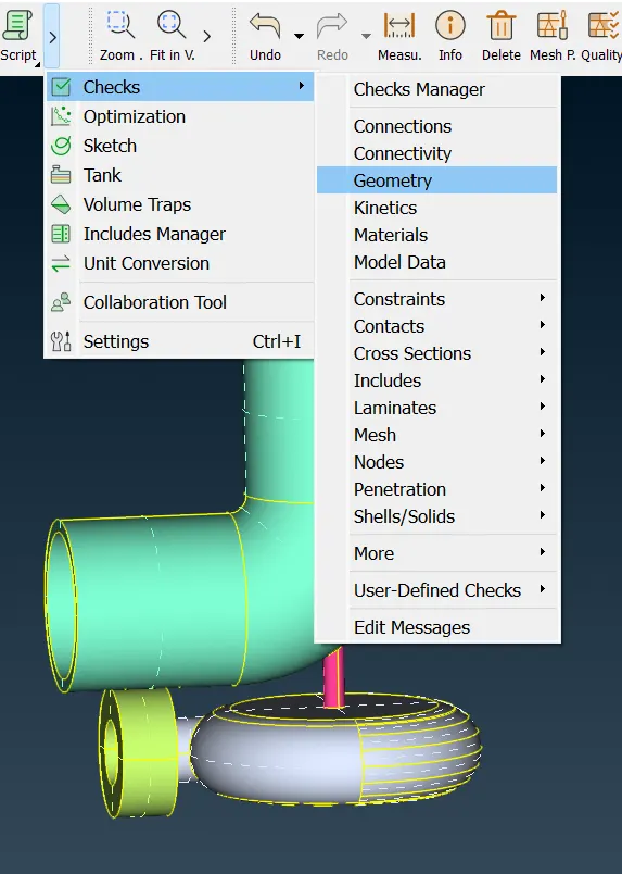
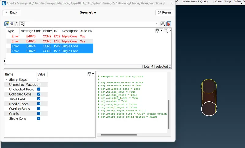
SINGLE CONS found.
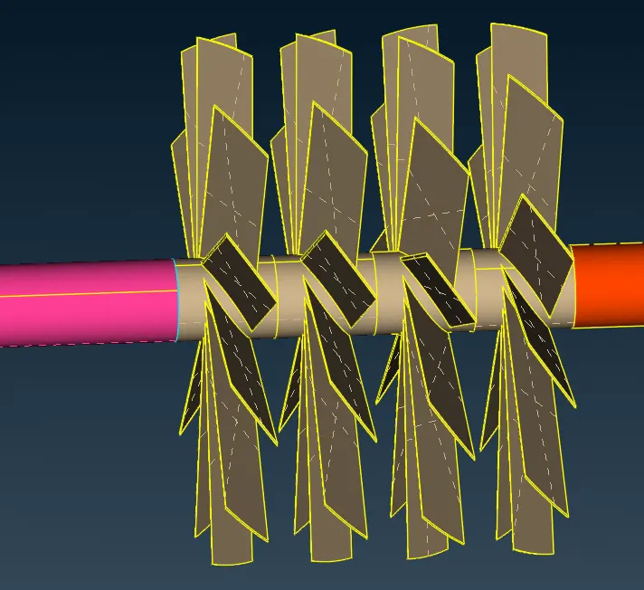
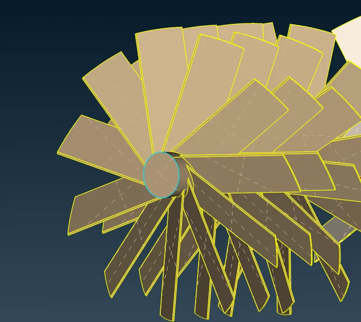
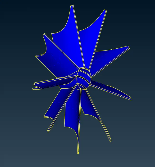
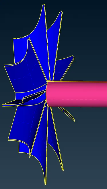
Similar way deleting the glitch in Blades.
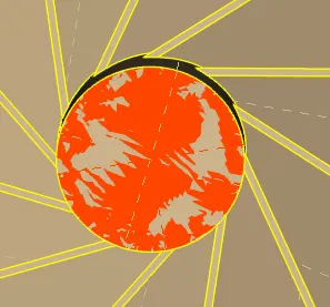
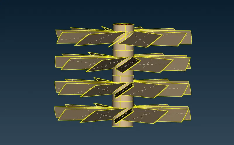
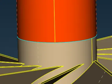

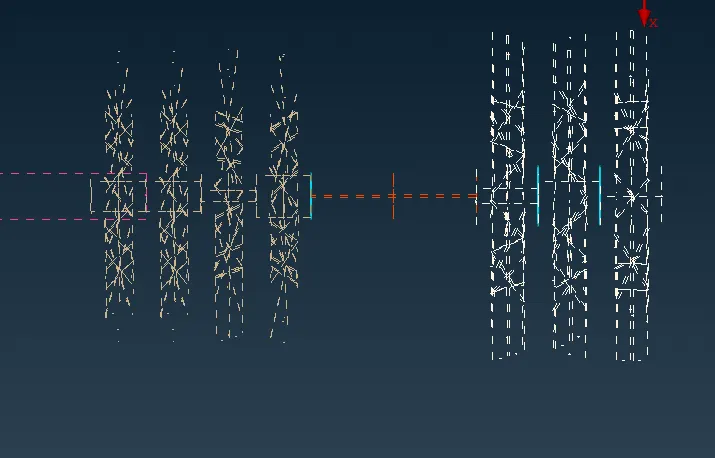
With the help of NOT command isolate the required surfaces and delete the overlapping region and do topo, where the triple cons are present will change into the double cons.
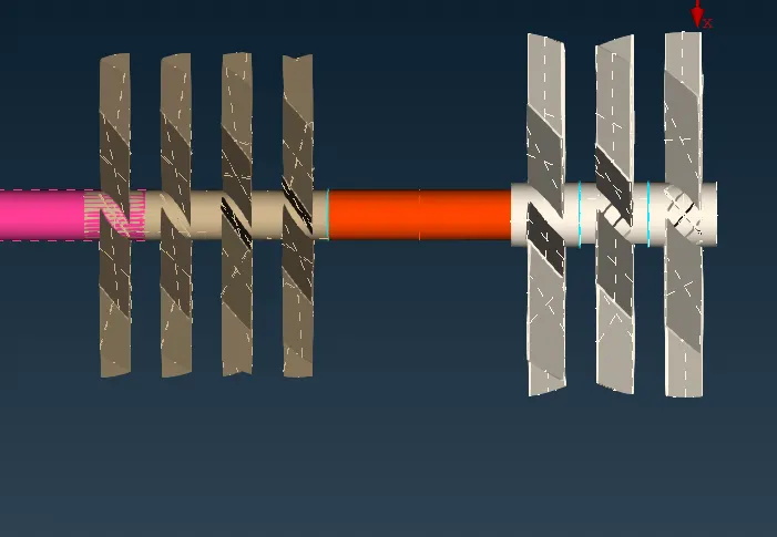
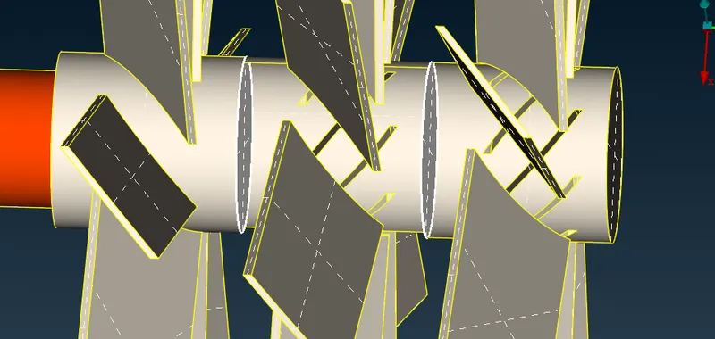
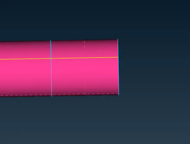
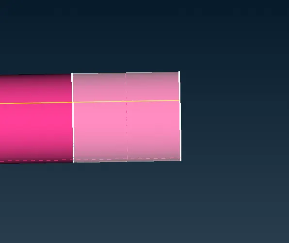
There is Glitch present in the Rotating Shaft, after deleting the overlapping surface project tool is used,where we need a pink surface over that region.
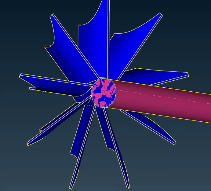
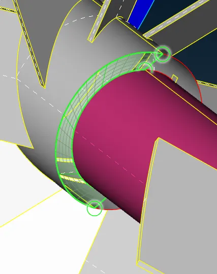
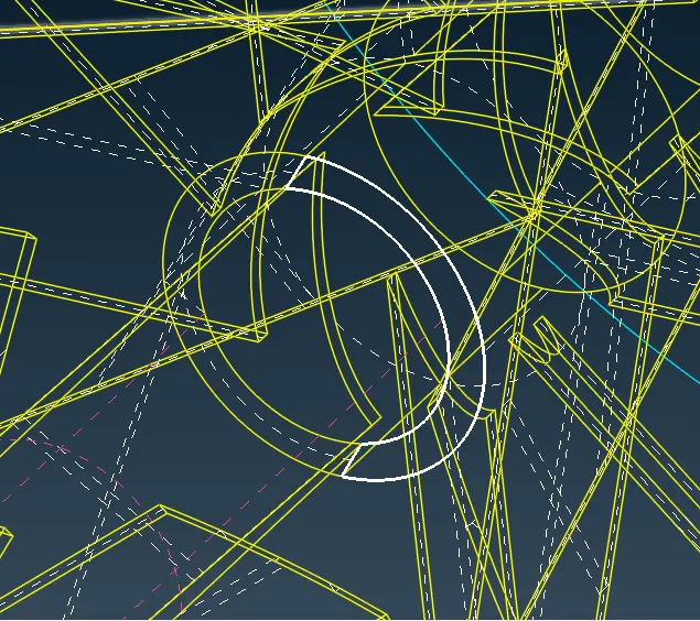
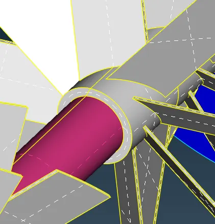
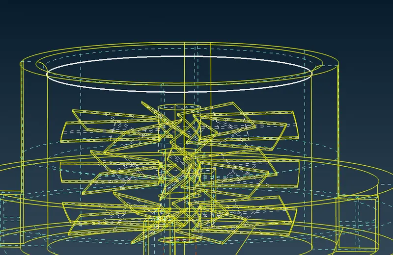
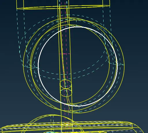
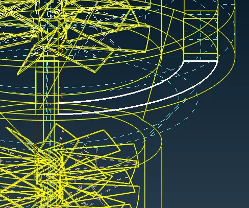
Filling the INLET, OUTLET Holes.
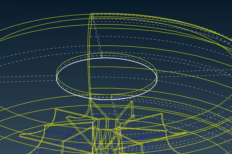
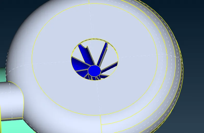
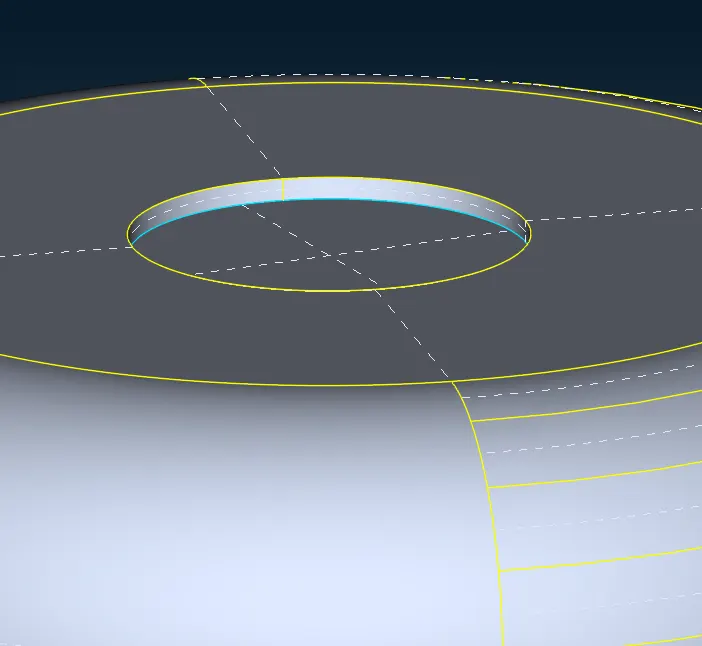
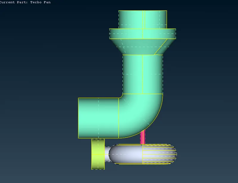
- FINAL GEOMETERY.
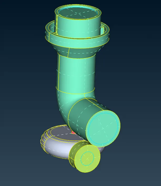
- BOUNDARY CONDITIONS.
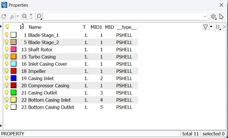

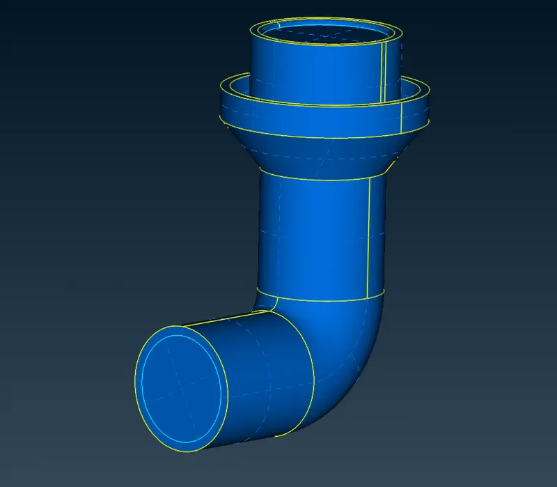


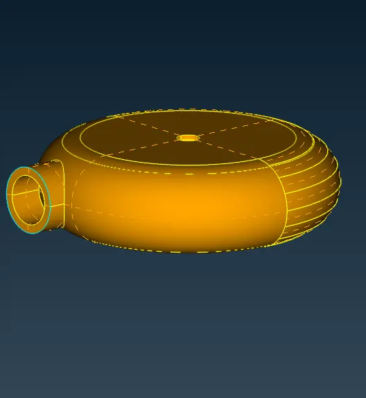
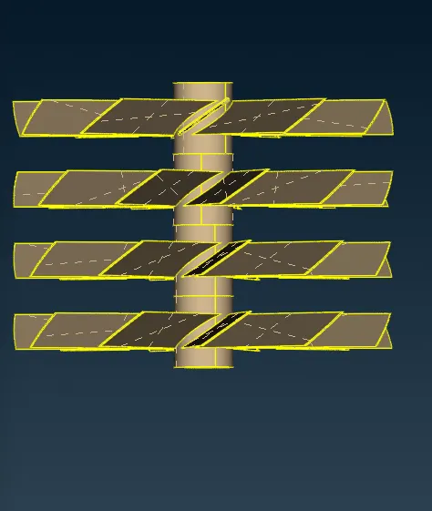


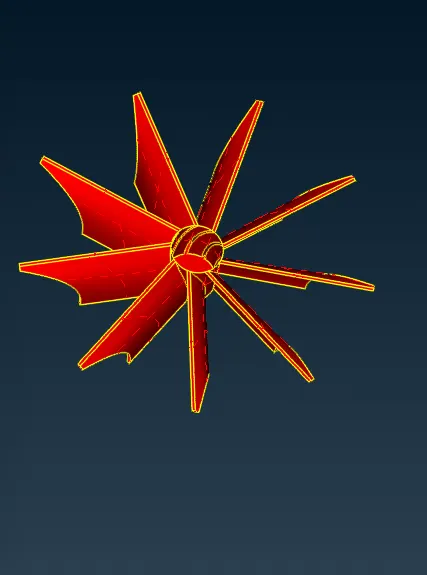
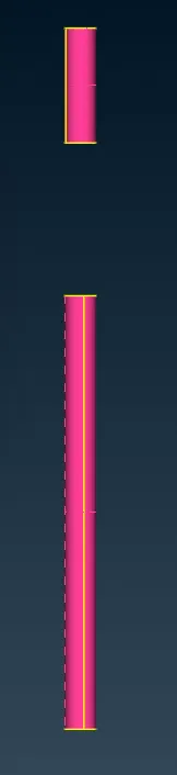
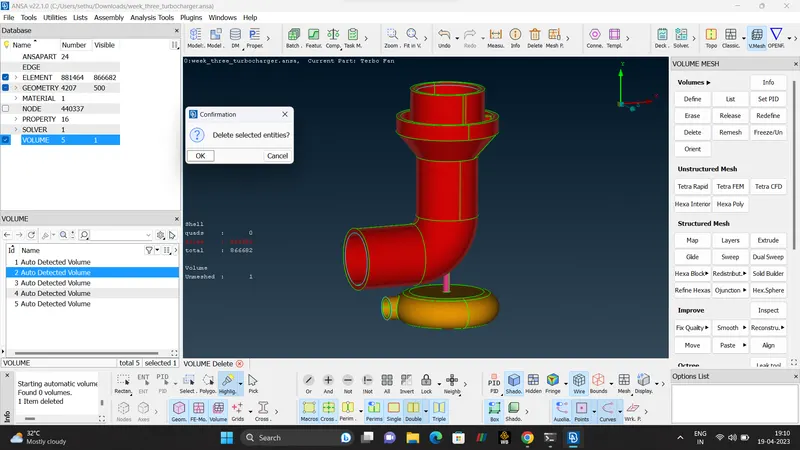
 DELETING THE EMPTY PIDs CONDITIONS.
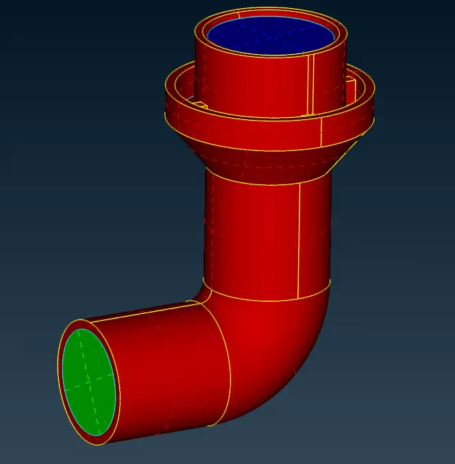
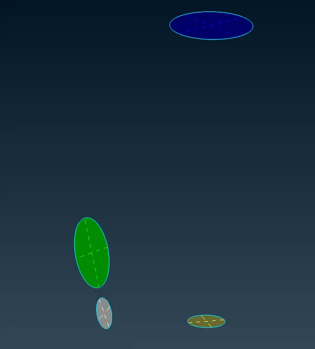
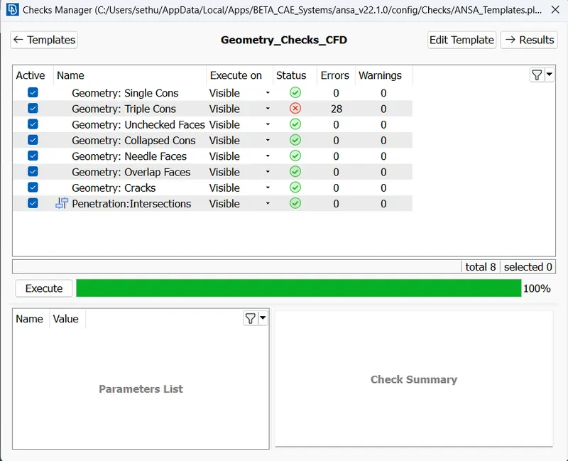
- CHECK-MANAGER.
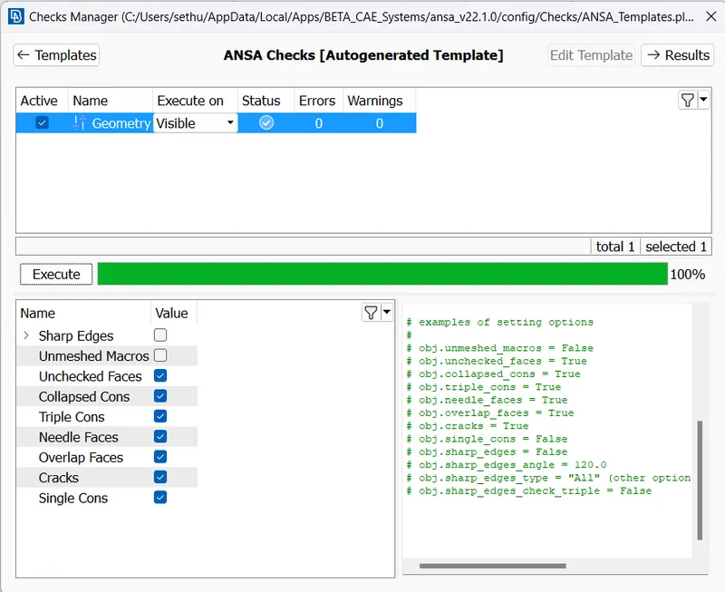
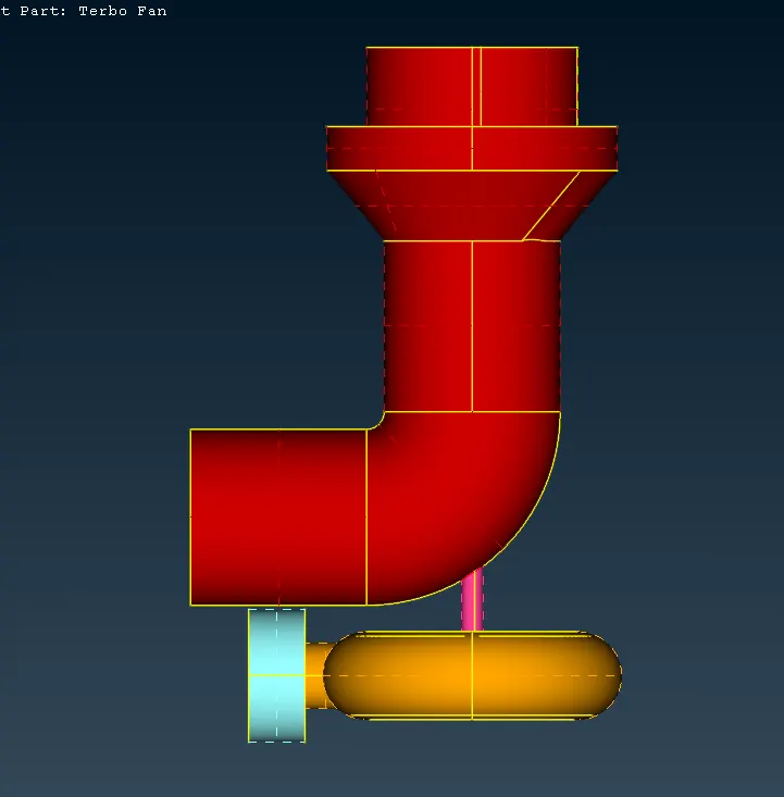
Again check-in is done to ensure that no Single Cons is present. There are 28 triples cons errors shows in the check manager, This triple cons are must required.
- MESHING.
A Mesh is a network that is formed of cells and points. It can have almost any shape in any size and is used to solve the PDEs (Partial Differential Equation). Each cell of the mesh represent an individual solution of equation which, when combined for the whole network, results in a solution for entire mesh.
TYPES OF MESHING.
Meshes are classified into two types,
SURFACE MESH
SOLID MESH/ VOLUME MESH
- SURFACE MESH.
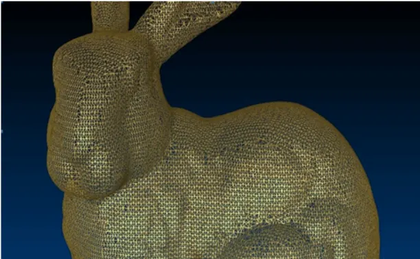
A surface Mesh is a representation of each individual Surface Constituting the Volume mesh. It consists of FACES and VERTICES. Depending on the Pre-processing Software, feature Curves also included.
Generally, a Surface Mesh should not have Free edges, and the edges should not be shared by two triangles.
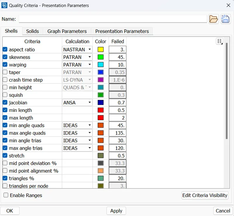
The Surfaces should contain the following qualities of triangles faces.
Equilateral Sized Triangles
No Sharp angles with the triangle Sphere
Gradual Variation in triangle Size from one to the next.
Surface Mesh generation process should be considered carefully. It has the Direct influence on the quality of the resulting Volume mesh and the effort it takes to get to this step.
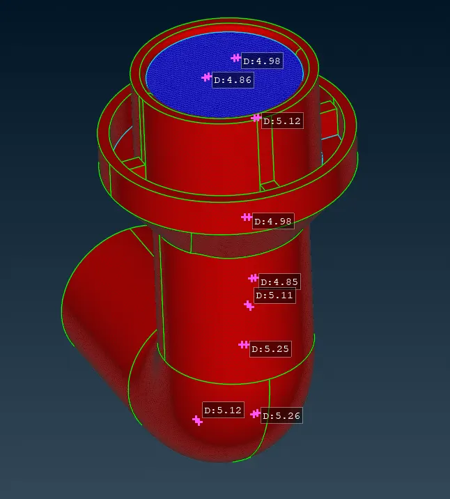
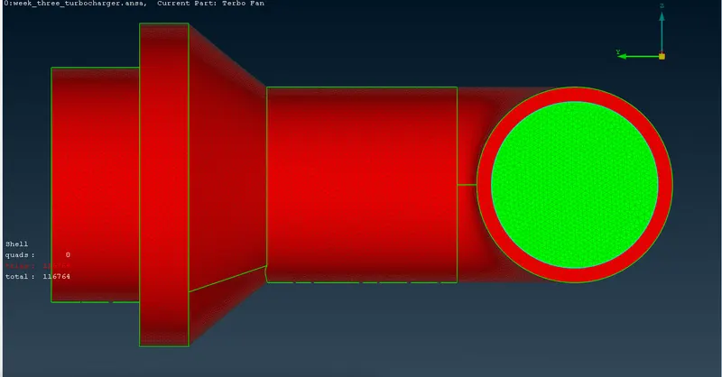
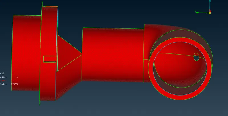
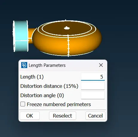
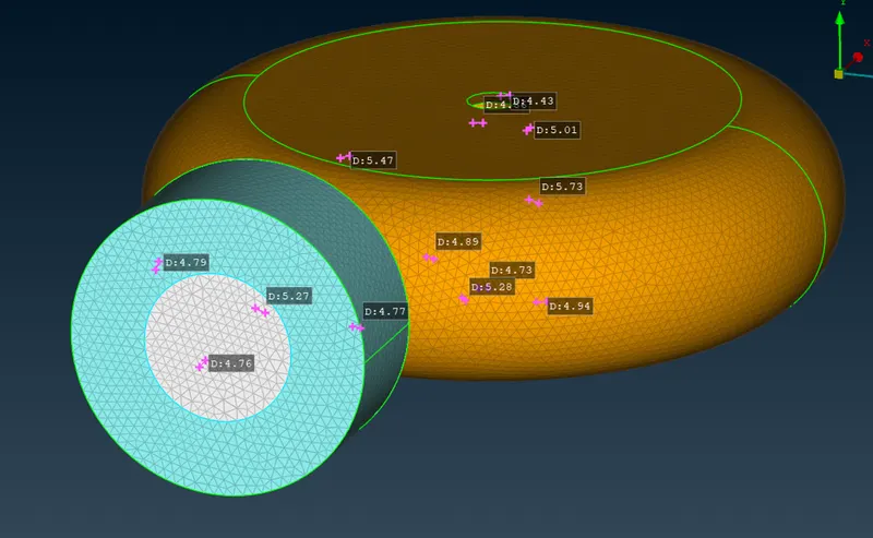
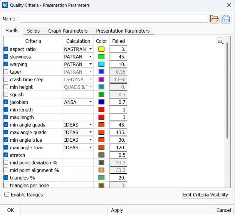
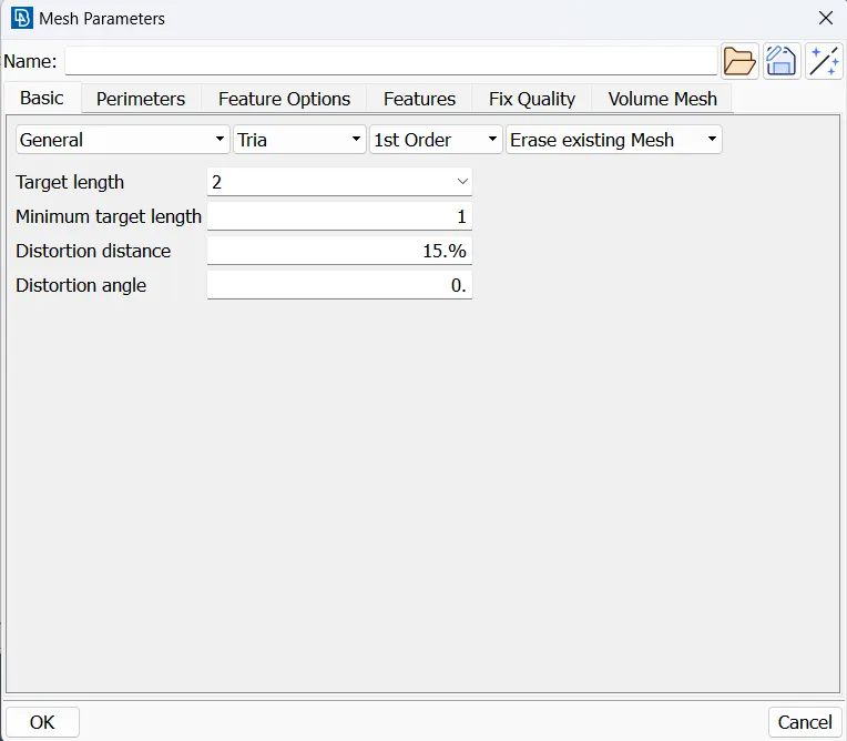
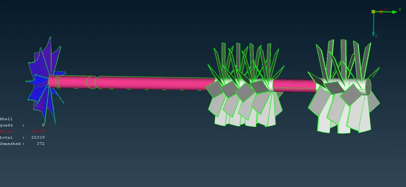
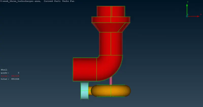
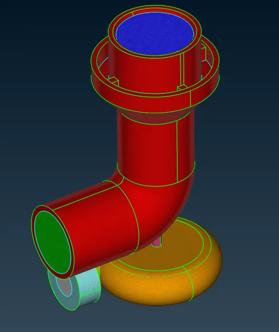
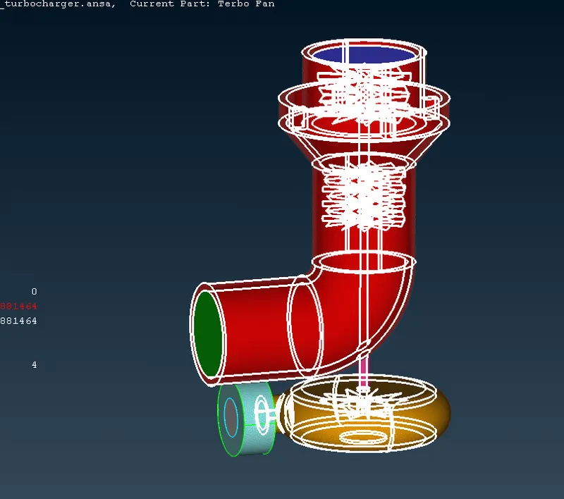
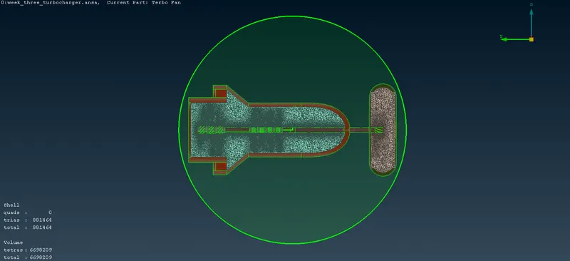
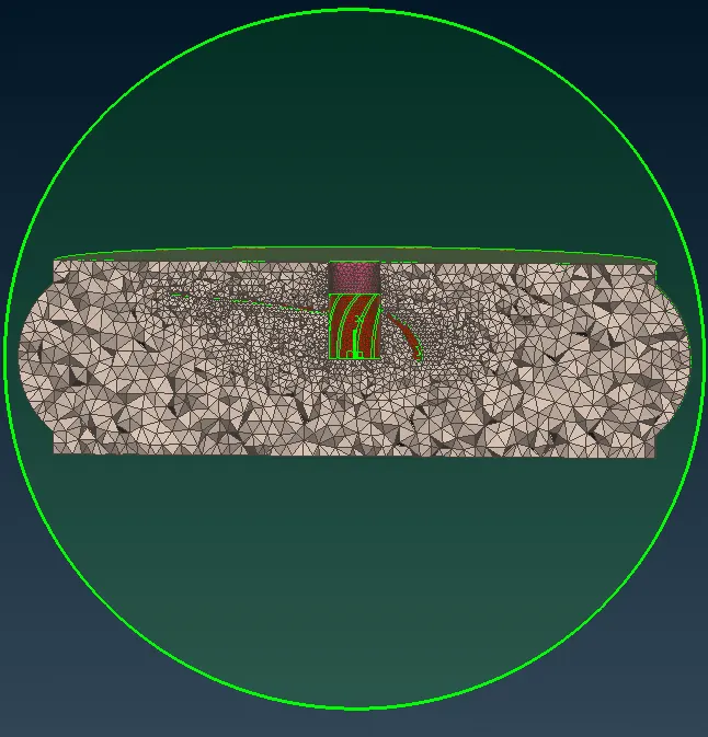
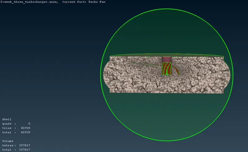
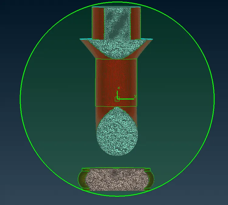
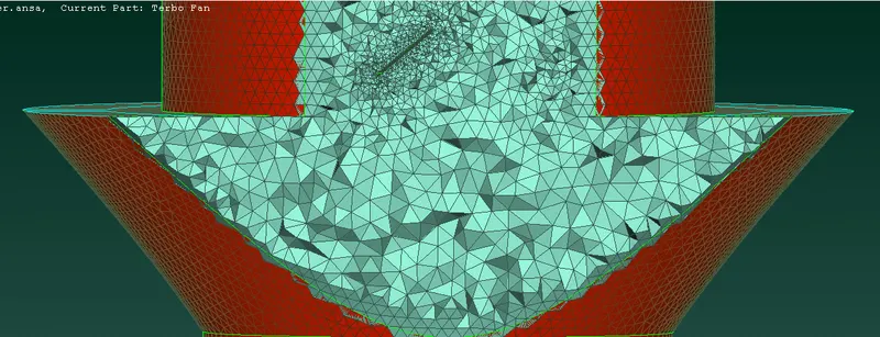
The MESHING is done perfectly in a way that when we cut(CROSS_SECTION VIEW)the plane, mesh is present inside the Compressor Casing.
- SOLID MESH.
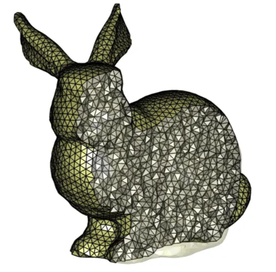
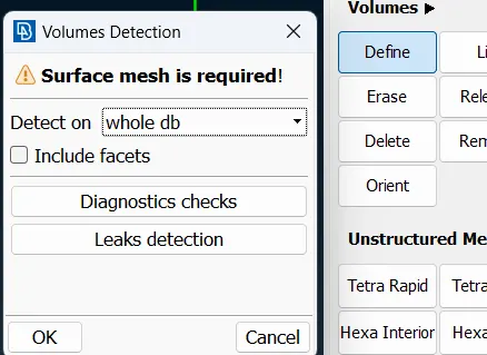
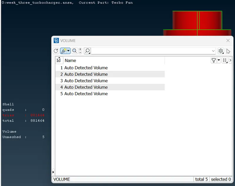
Solid Mesh, also known as volume mesh, is a polygonal Mesh representation of the interior Volume Of an Object. There are different types of meshing models that can be used to generate a volume mesh from a well prepared surface mesh.
Three Types of Meshing models are follows
TETRAHEDRAL - Tetrahedral cell shape based core mesh.
POLYHEDRAL - Polyhedral cell shape based core mesh.
TRIMMED - Trimmed hexahedarl cell shape core mesh.
Once the volume mesh has been built, It can be checked for errors and exported to the other packages if desired.
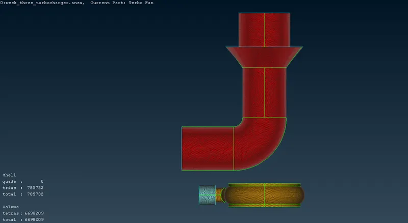
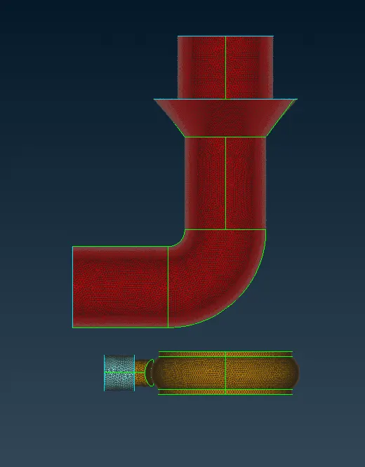
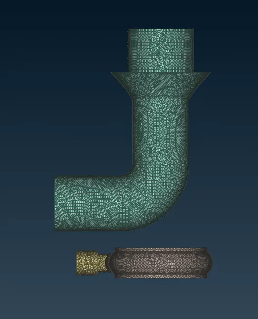
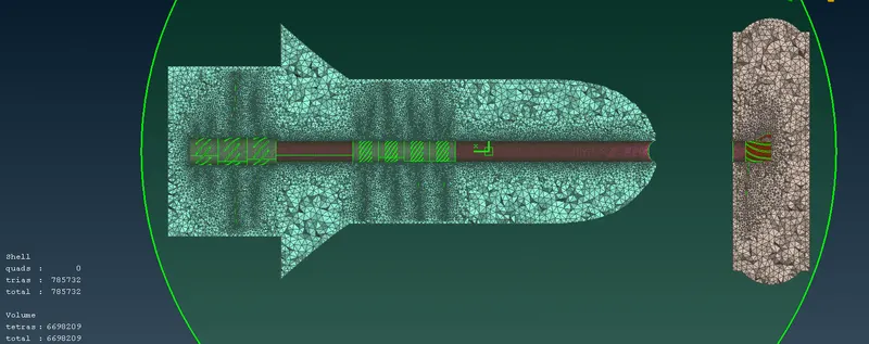
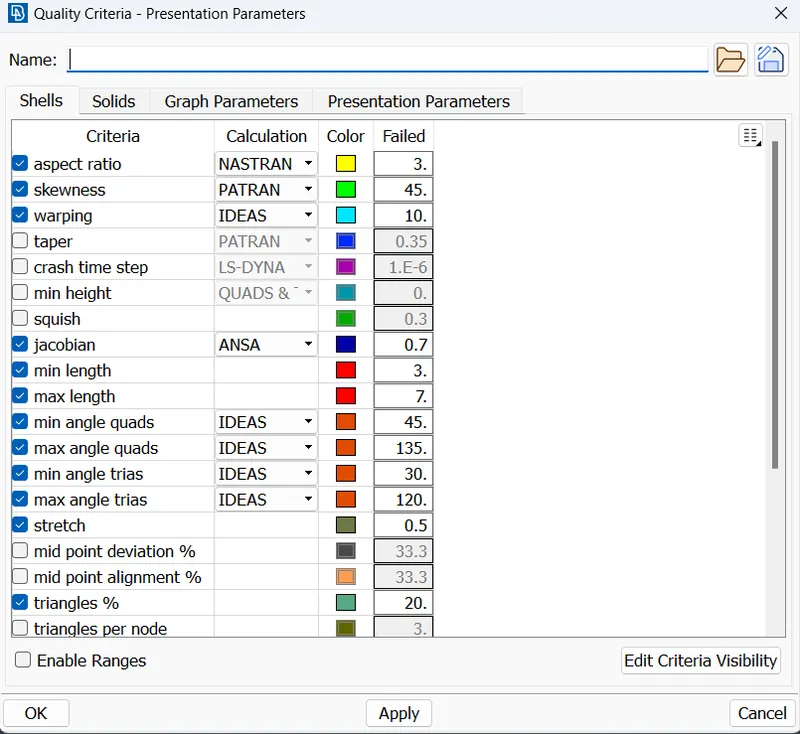
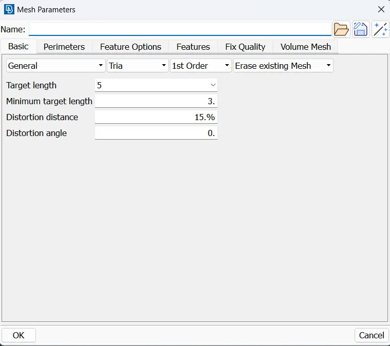
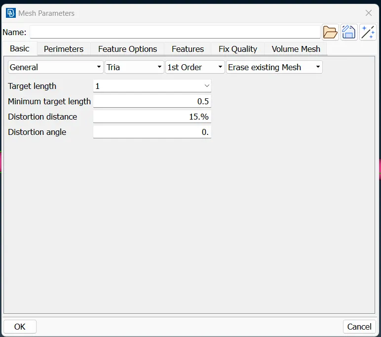
| NO | BOUNDARY CONDITIONS - PIDs | MESH SIZE | MESH TYPE | MINI LENGTH | MAX LENGTH |
| 1 | Blade Stage_ 1 | 1mm | Tria | 0.5 mm | 2 mm |
| 2 | Blade Stage_ 2 | 1mm | Tria | 0.5 mm | 2 mm |
| 3 | Impeller | 2mm | Tria | 1 mm | 4 mm |
| 4 | Shaft Rotor | 1mm | Tria | 0.5 mm | 2 mm |
| 5 | Turbo Casing | 5mm | Tria | 3 mm | 7 mm |
| 6 | Compressor Casing | 5mm | Tria | 3 mm | 7 mm |
| 7 | Inlet Casing Cover | 5mm | Tria | 3 mm | 7 mm |
| NO | MESH | NO OF ELEMENTS |
| 1 | SURFACE MESH 2D ( SPOT MESH) | 785732 |
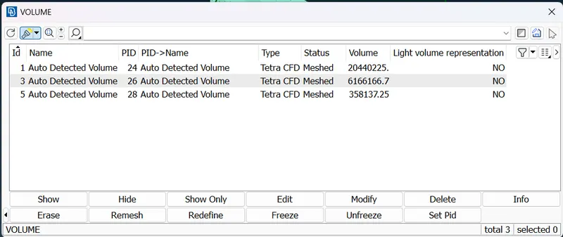
| 2 | VOLUMETRIC MESH 3D (TETRA CFD MESH) | 6698208 |
- CONCLUSION.
Geometric errors like Single cons, Triple Cons, Missing surfaces and Overlapping surfaces are identified and also rectified the errors.
Hence we can conclude that Both Surface Mesh and Volumetric Mesh is done respectively and results are satisfied.
Volumetric mesh is done after completing the Surface mesh. In Volumetric mesh, meshing process takes more computational time compare to the surface mesh.