Week 4 - CHT Analysis on Exhaust port
AIM :-
- To Simulate the Conjugate Heat Transfer Analysis On Exhaust Port Using Ansys Fluent.
OBJECTIVES :-
- Give a brief description of why and where a CHT analysis is used.
- Maintain the y+ value according to the turbulence model and justify the results.
- Calculate the wall/surface heat transfer coefficient on the internal solid surface & show the velocity & temperature contours in appropriate areas.
- How would you verify if the HTC predictions from the simulations are right? On what factors does the accuracy of the prediction depend on?
PROCEDURE :-
Conjugate Heat Transfer
Heat Transfer Coefficient
Heat Transfer
- HEAT TRANSFER
DEFINITION:-
- Heat transfer is defined as the movement of heat across the border of the system due to a difference in temperature between the system and it's surroundings.
HOW HEAT TRANSFERRED:-
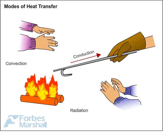
- Heat can travel from one place to another in serval ways, They include
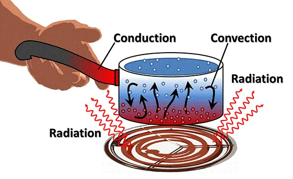
1. Conduction.
2. Covection.
3. Radiation.
- If temperature difference exist between two system, heat will find a way to transfer from the higher system to the lower system.
- CONDUCTION.
DEFINITION:-
- Conduction is defined as the process of transmisson of energy from one particle of medium to another with particles beings in direct contact with each other.
- The Conduction equation is expressed as,
| `Q = (K *A*(T_(hot)-T_(cold)))/d` |
- The Co-efficient of the thermal conductivity shows that a metal body conducts heat better when it comes to conduction.
| Q | Heat Transfer per unit Time |
| K | Thermal Conductivity of the Body |
| A | Area of Heat Transfer |
| `T_(hot)` | Temperature of the Hot Region |
| `T_(cold)` | Temperature of the Cold Region |
| d | Thickness of the Body |
- CONVECTION.
DEFINITION:-
- Convection is defined as the movement of fluid molecules from Higher temperature region to Lower temperature region.
- The Convection equation expressed as,
| `Q = h_c *A*(T_s -T_f)` |
| Q | Heat Transfer per unit Time |
| A | Area of Heat Transfer |
| `T_s` | Surface Temperature |
| `T_f` | Fluid Temperature |
- CONJUGATE HEAT TRANSFER.
DEFINITION:-
- Conjugate Heat Transfer is a concept of heat transfer involed in both fluids and solids simultaneously.
- For Solving Conjugate Heat Transfer problems, we use both the Conduction and Convection Equations for the revelant phase of material.
- Conjugate Heat Transfer corressponds with the combination of Heat Transfer in Solids and Fluids.
- In Solids, the Conduction Often dominates Whereas in Fluids, the Convection often dominates.
An Animation of Conjugate Heat Transfer Analysis On Exhaust Port

- CONJUGATE HEAT TRANSFER APPLICATIONS.
Effective Heat Transfer.
- Efficiently combining heat transfer in fluids and solids is the key to designing effective coolers, heaters or heat exchanges. The fluid usually plays the role of energy carrire on large instances. Forced convection is the most common way to achieve high heat transfer.
Energy Savings.
- Heat transfer in fluids and solids can be combined to minimize heat losses in various devices, because most gases(especially at low pressure) have small thermal conductivities, they can be used as thermal insulation.
Electromobility.
- Effective cooling strategies are critical for various components of emobility system. Electric motors, have high power densities and thus generate a significant amount of heat. If a motor is not properly cooled, high temperature in the motor can cause the demagnetization of permanent magnets and breakdown of windings modulation.
- HEAT TRANSFER COEFFICIENT.
DEFINITION:-
- Heat Transfer Co-efficient also known as Film Co-efficient or Film Effectiveness, is a measure of non-dimensionality for understanding the increase in temperature of flow by a degreee when certain heat supplied to the flow over the cross-section of the flow. It signifies the heat transfer of heat between a fluid medium and to surface flowed over by the fluid.
| `h = q/(delT)` |
| h | Heat Transfer Co-efficient of the flow `W/(m^2-k)` |
| q | Heat Flux `W/m^2` |
| `delT` | Diff in Temp between Solid Surface and Fluid Area, Kelvin(K) |
CASE 1. - BASE LINE MESH.
- MODEL - EXHAUST MANIFOLD.
- GEOMETRY
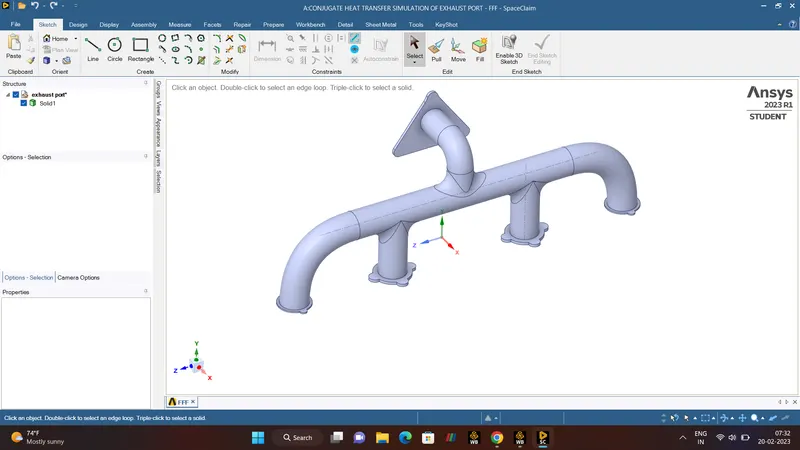
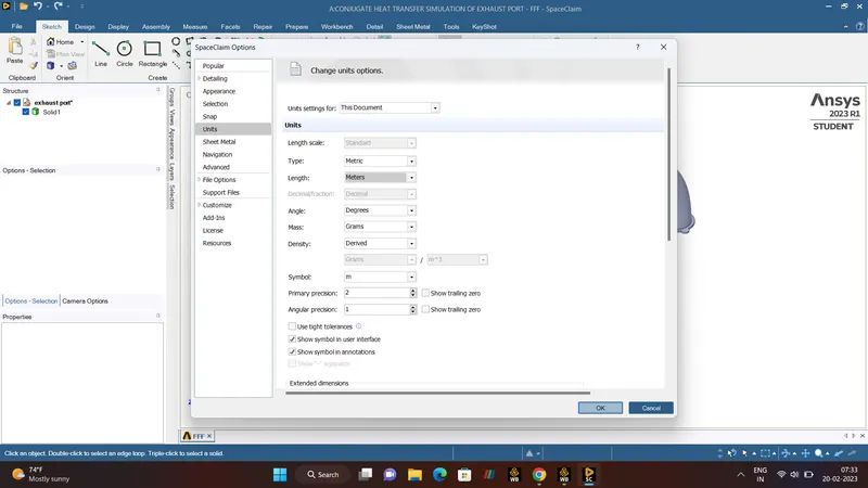
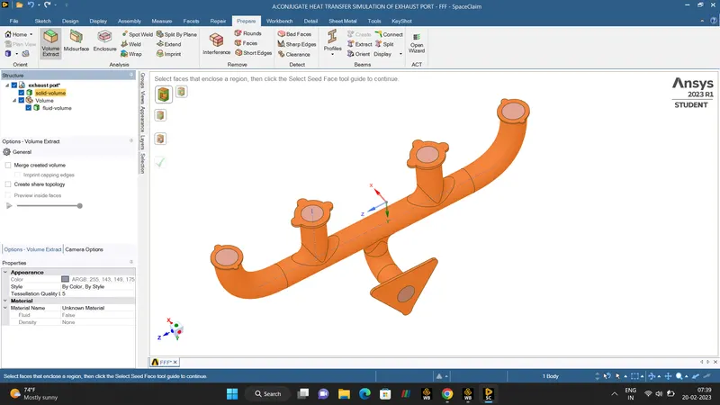
In SPACECLAIM, CAD model of the exhaust manifold port is loaded and UNITS needs to be changed from Millimeters to Meters. After that need to check whether there is an extra edges in the model, if we found any extra edges then it needed to be deleted, we can clearly able to see in the third image there is no extra edges (NO AREA FOUND).
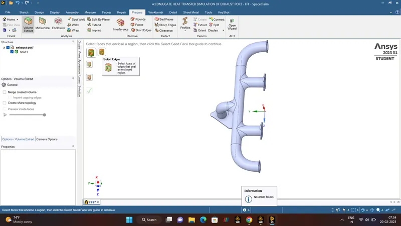
- VOLUME EXTRACT
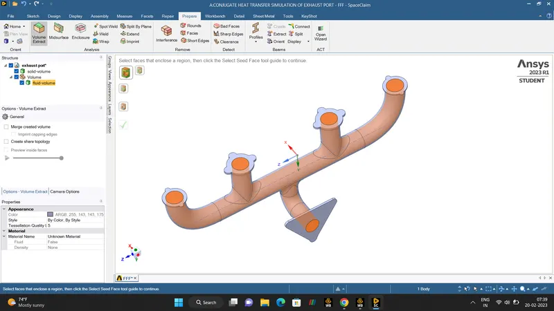
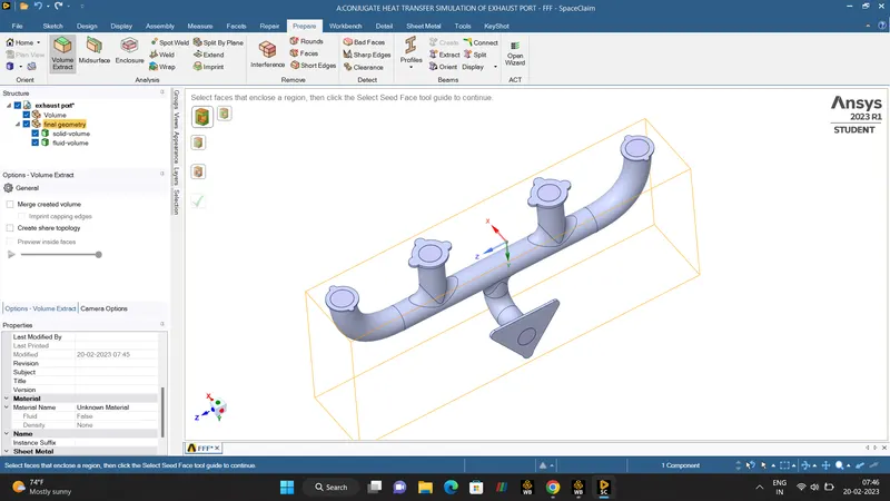
With the help of Repair section, In Volume Extract tool select the EDGE volume, then click the INLETs and OUTLET ports name it as the fluid volume and solid volume respectively. Combine the fluid and solid volume into a final geometry, then delete the empty component.
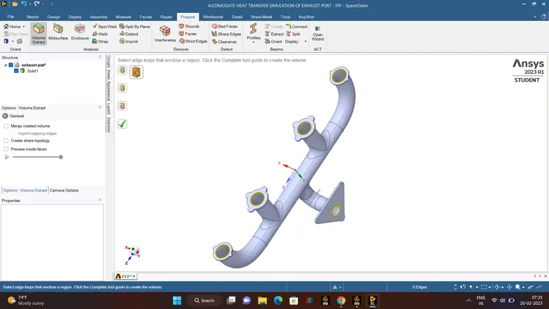
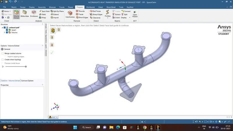
- FLUID AND SOLID VOLUMES.
In the left image, it is clearly shown that the inner surface of the fluid volume and right image specifices the solid surface.
- SHARE TOPOLOGY.
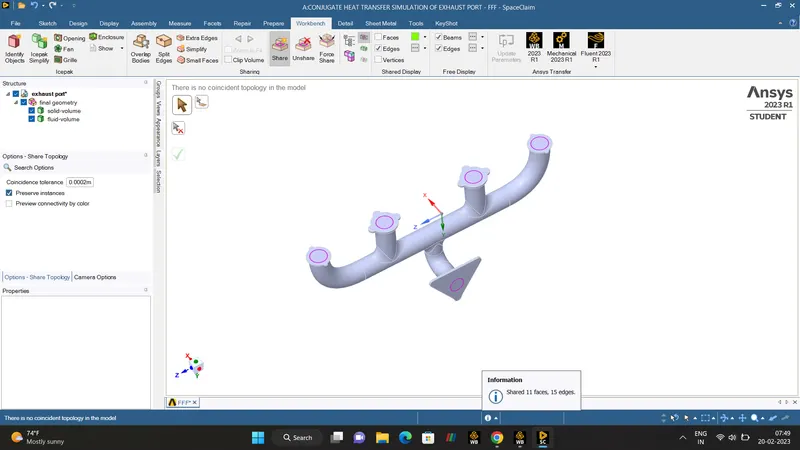
Finally Share topology is used-(WORKBENCH>SHARE PREPARATION)
- BENIFITS.
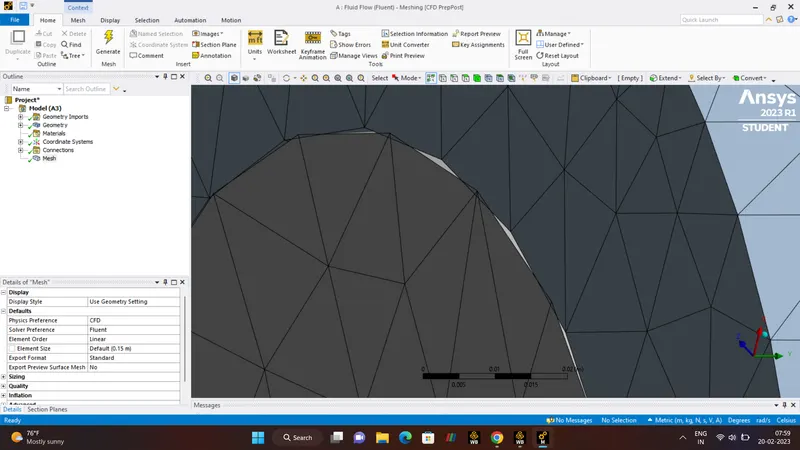
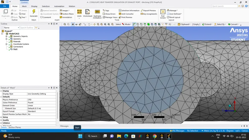
The purpose of share topology is to ensure that the EXHAUST PORT of both the fluid and solid volume bodies is connected to the single body where the faces is been shared, which help the creation of Conformal mesh.
we can able to see the 11 faces and 15 edges been shared and there is an pink colour all over the circles.
- STEP 2:- MESHING.
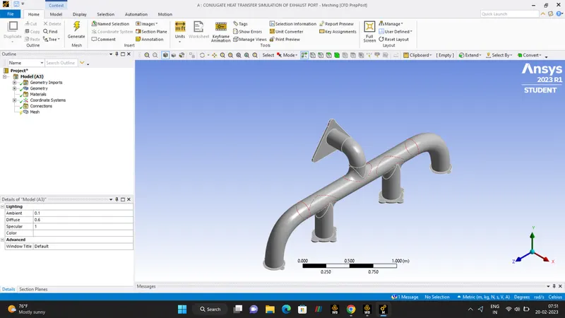
MESHING is the major part of Engineering Simulation process. Here larger geometry is Discretized into a small simple elements in order to get a Accurate Solution.
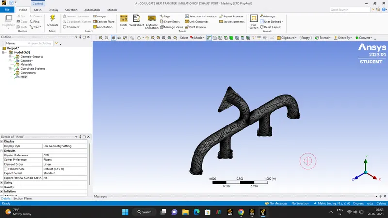
WITHOUT SHARE TOPOLOGY.
BEFORE
Without share topology we can Clearly able to see the a gap between the meshes. AFTER
- NAME SELECTION.
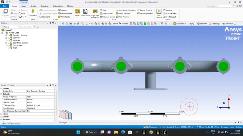
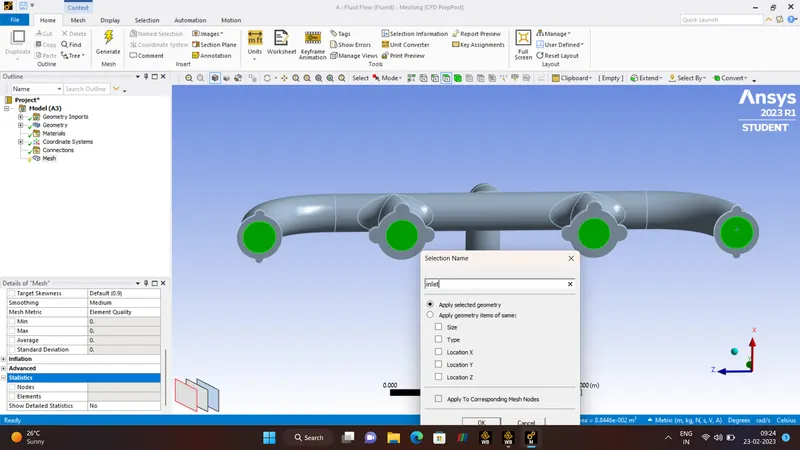
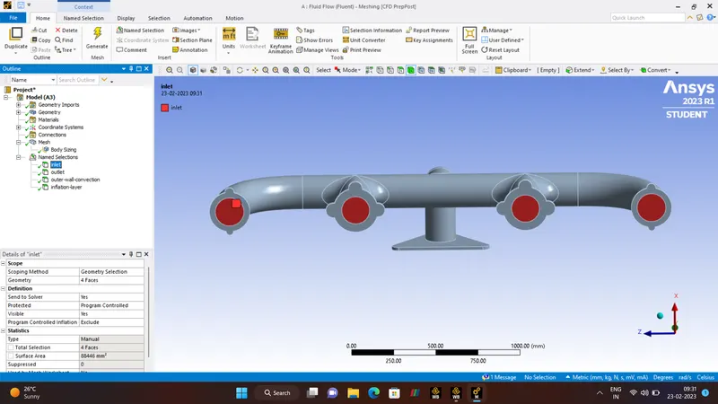
INLETS
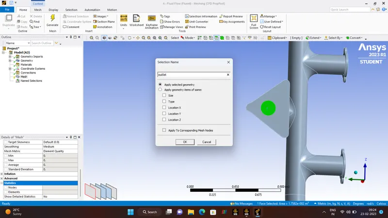
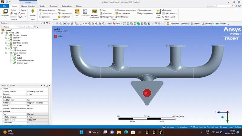
OUTLET
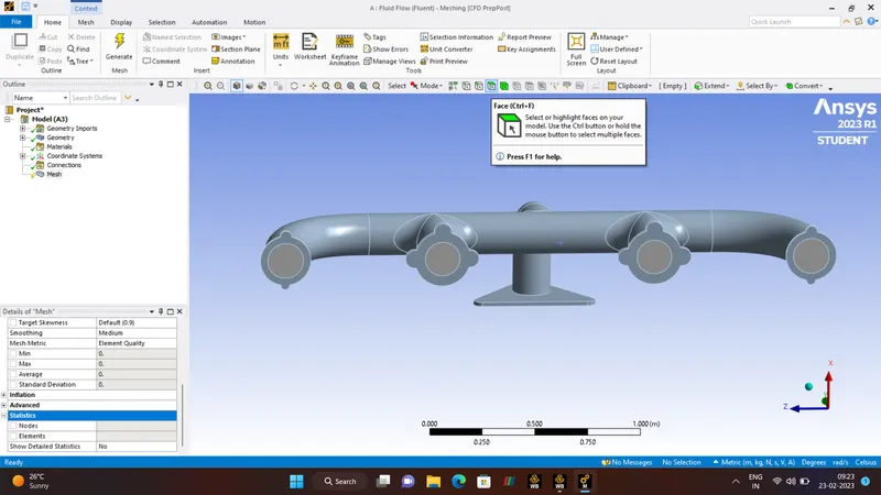
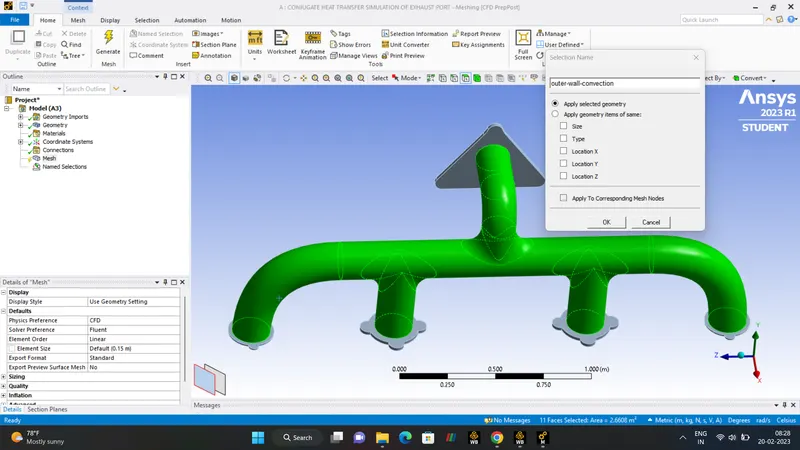
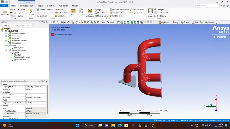
OUTER-WALL-CONVECTION.
To specfiy the names of Inlet, Outlet, Outer-wall-convection the FACE selection tool is used (CNTRL + F) is used.
MESHING.
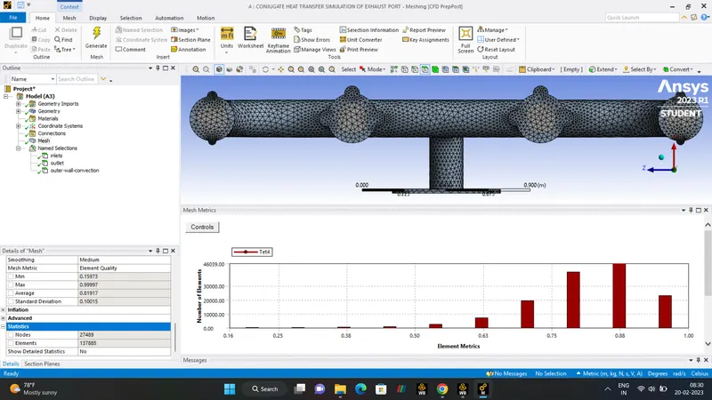
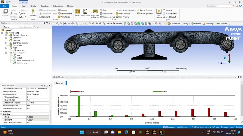
A general BASE LINE MESH is done, ELEMENT QUALITY is checked.
NUMBER OF ELEMENTS - 137885.
NUMBER OF NODES - 27489.
- STEP 3:- SETUP.
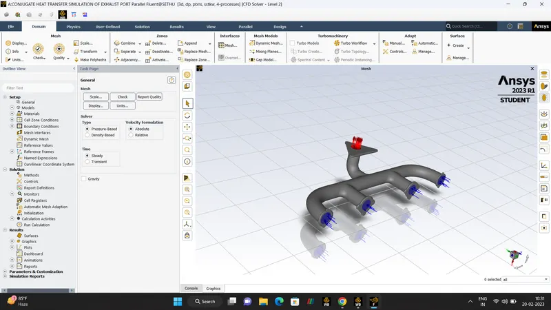
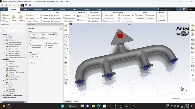
SETUP
| SOLVER | PRESSURE-BASED-SOLVER |
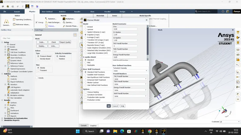
| MODEL | TURBULENCE MODEL |
| VISCOUS | K-EPSILON |
| ENERGY | ON |
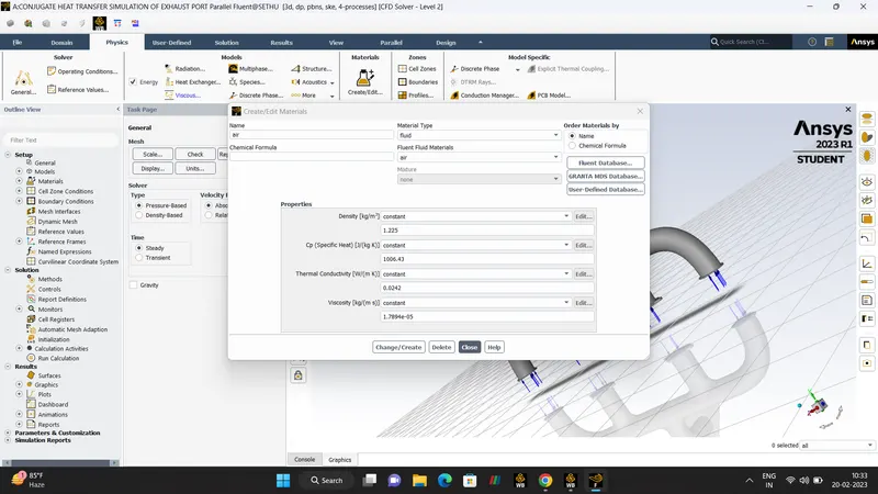
| MATERIAL |
FLUID (AIR) SOLID (ALUMINUM) |
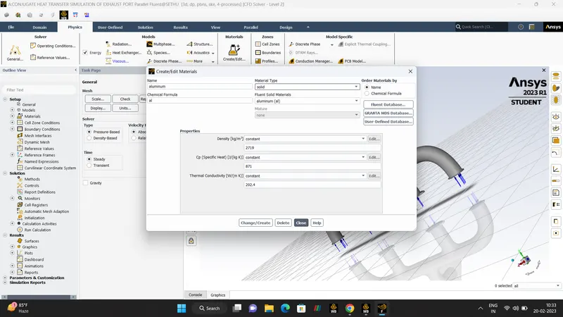
BOUNDARY CONDITIONS
| INLET | VELOCITY |
| VELOCITY | 5 m/s |
| TEMPERATURE | 700K |
| OUTLET | PRESSURE |
| OUTER-WALL-CONVECTION |
HEAT-TRANSFER-COEFFICIENT CONVECTION-20 |
|
FINAL GEOMETRY CONDITION |
NO-SLIP |
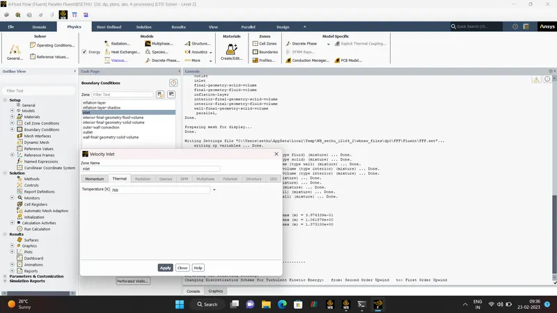
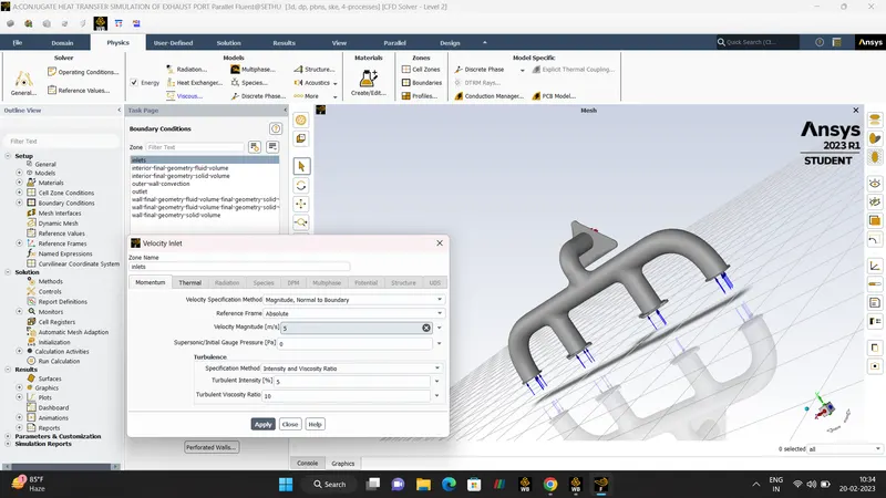
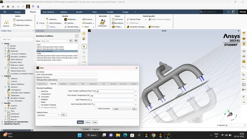
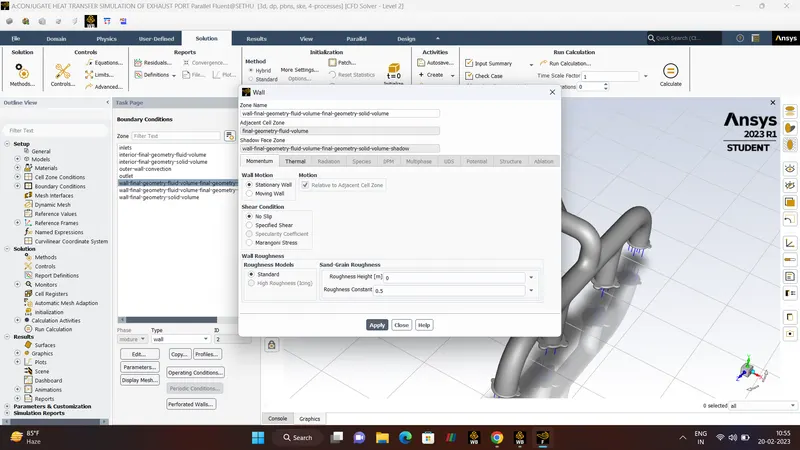
PRESSURE-BASED-SOLVER.
- Pressure-Based-solvers was developed for 'Low-Speed Incompressible Flow' and midly compressible flow.
- This solver uses Momentum and Pressure as the primary Variables.
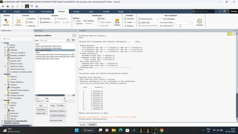
HYBRID INITIALIZATION
- Hybrid Initialization is the collection of recipes and boundary interpolation method. It solves the Laplace's Equation to the determine the Velocity, Temperature, Pressure field.
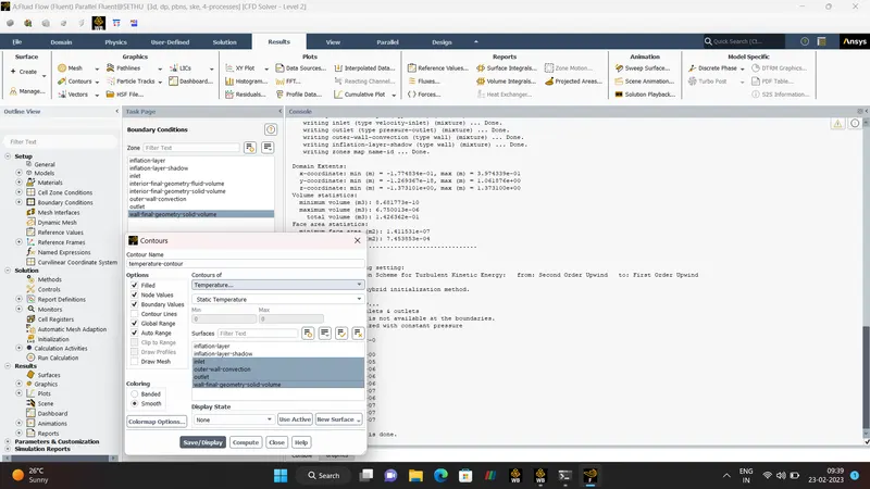
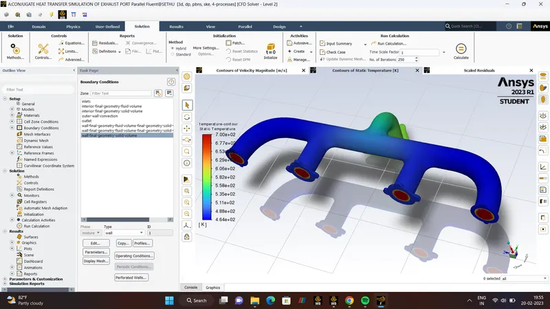
- RESULTS.
VELOCITY TEMPERATURE.
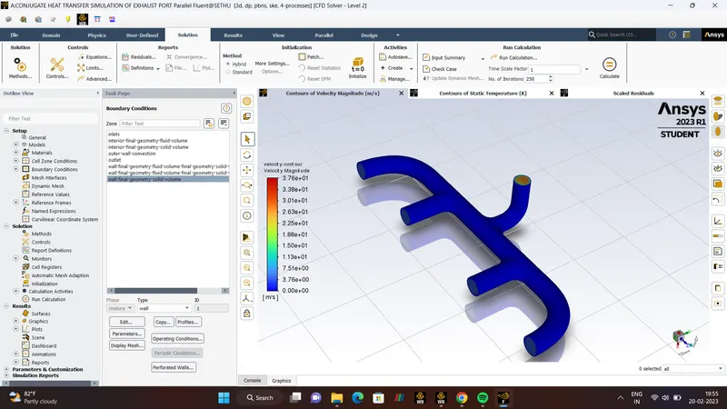
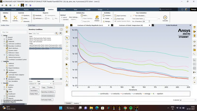
RESIDUAL.
- STEP- 4:- POST-PROCESSING.
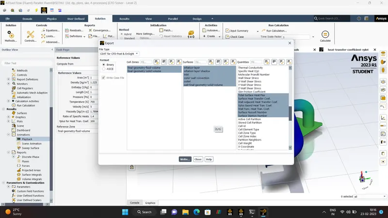
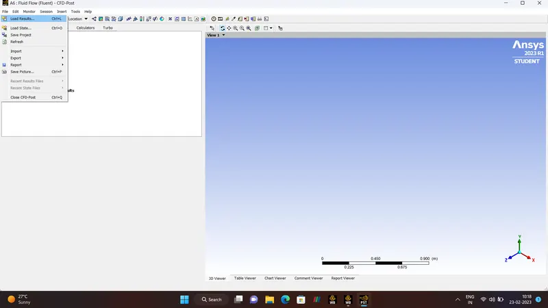
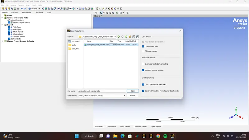
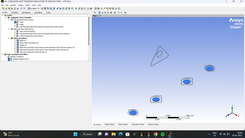
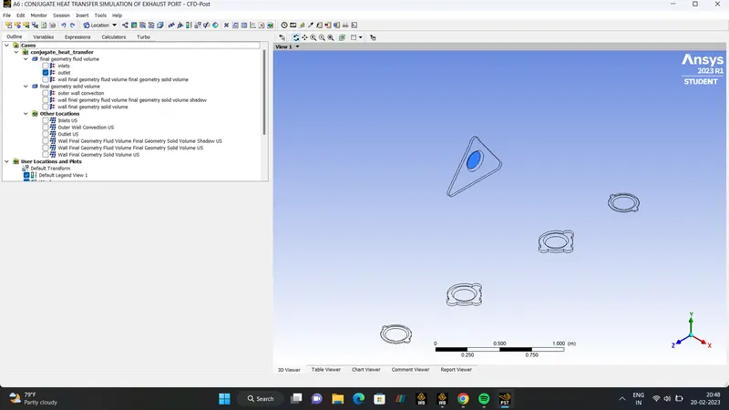
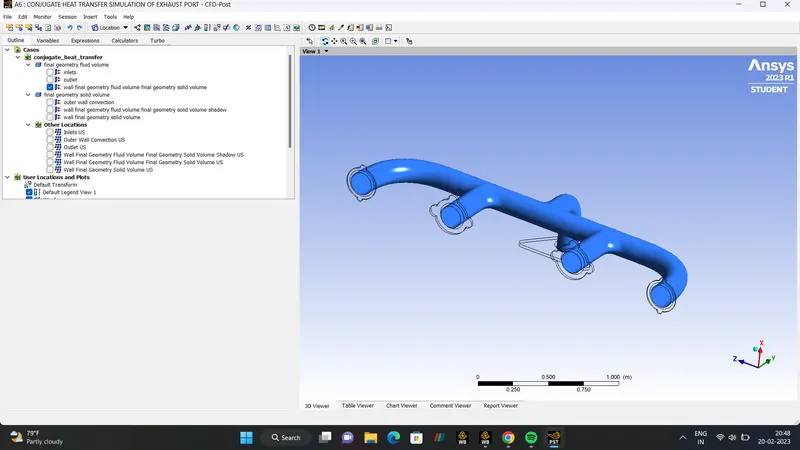
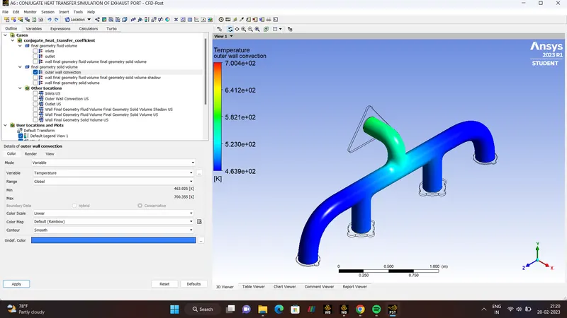
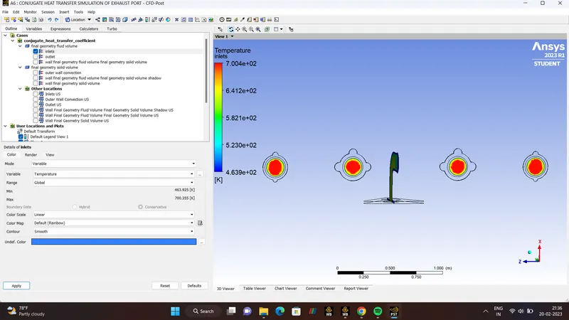
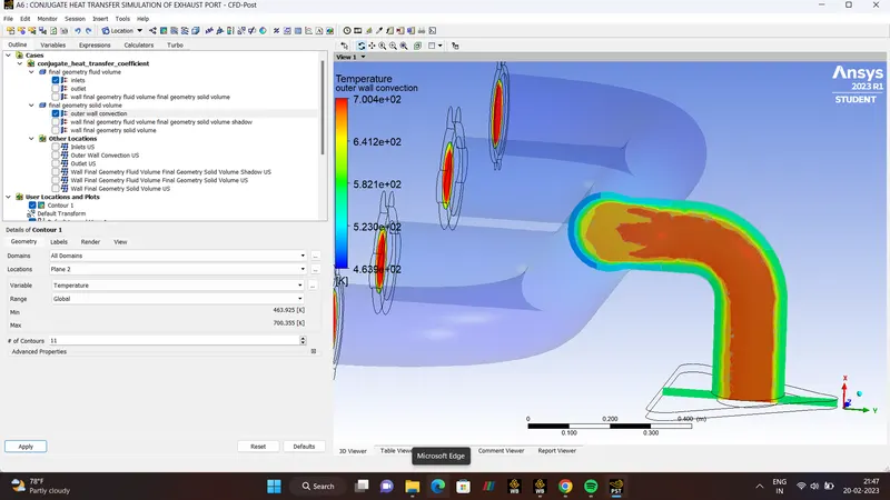
CHECK-( INLET, OUTLET, OUTER-WALL-CONVECTION, FINAL-GEOMETRY)
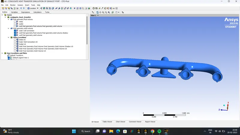
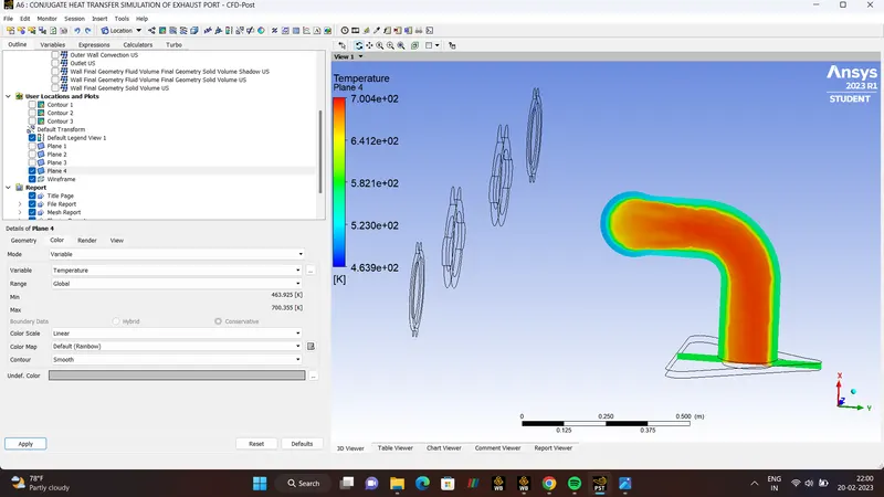
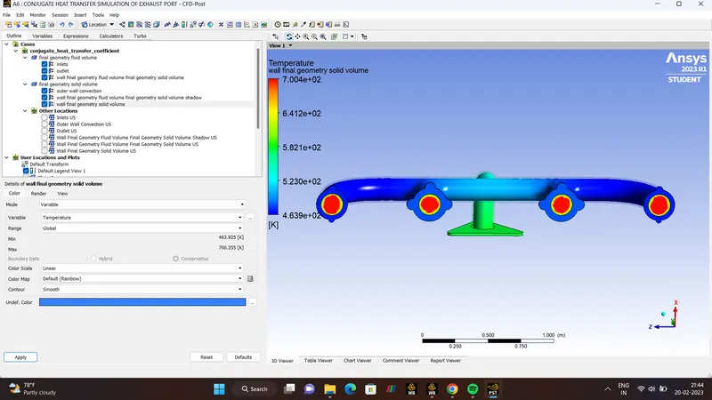
TEMPERATURE.
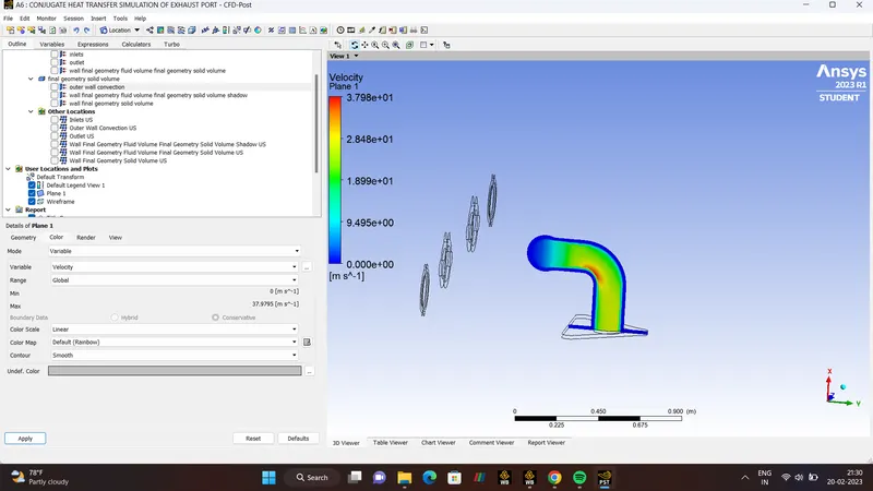
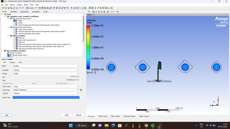
VELOCITY.
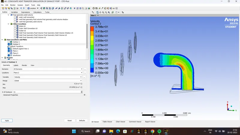
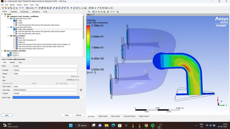
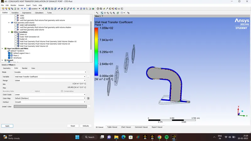
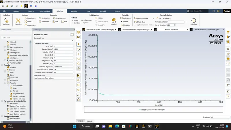
HEAT TRANSFER CO-EFFICIENT.
CASE-2
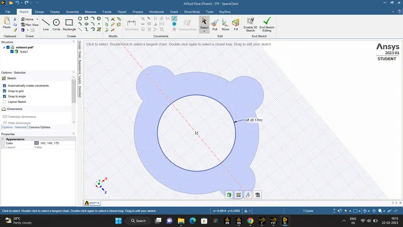
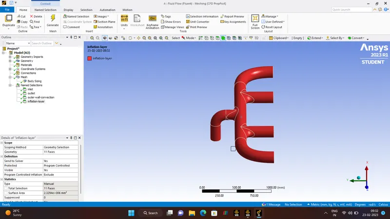
NAME SELECTION.
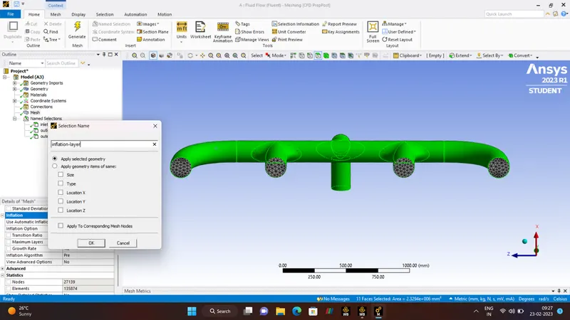
INFLATION-LAYERS
OUTER- WALL-CONVECTION.
OUTLET
INLETS.
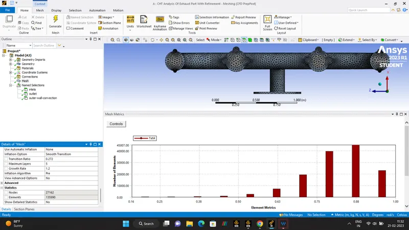
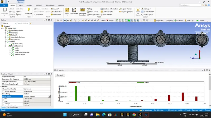
MESHING.
GENERAL MESH - 70mm
NUMBER OF ELEMENT - 135990.
NUMBER OF NODES - 27162.
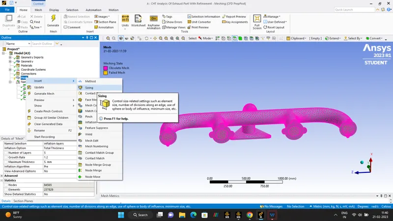
INFLATION.
- Real geometry are complex and we often need to use an unstructured mesh.Unstructured mesh are thin close near to the wall.
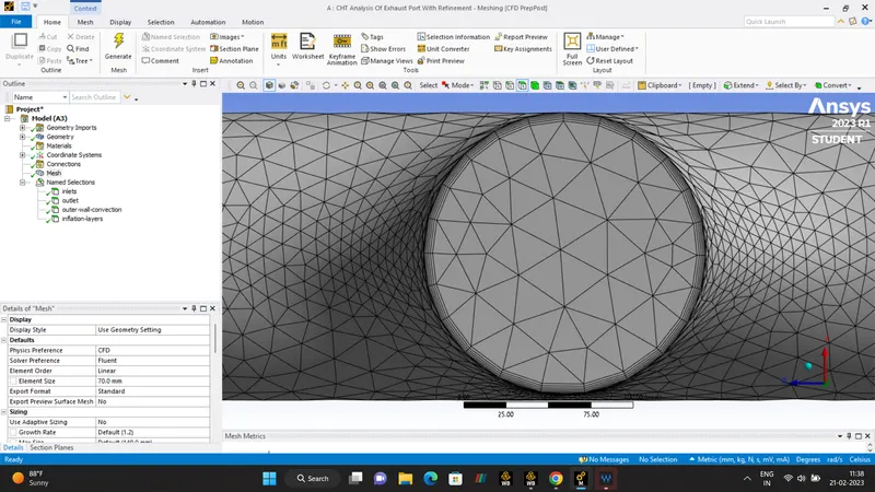
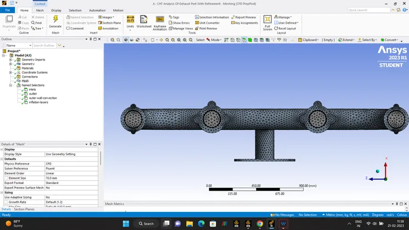
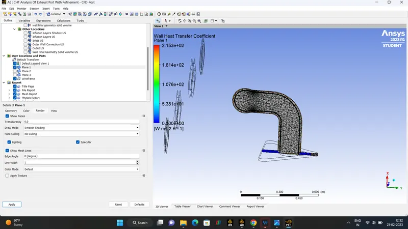
- So the Inflation layer is used to create thin element that can capture the normal gradient with minimal element which uses to correctly capture the VELOCITY and TEMPERATURE gradient near NO-SLIP wall.
| INNER DAIMETER | 0.17m |
| INFLATION | 5mm |
| NUMBER OF INFLATION-LAYERS | 5 |
| GROWTH RATE | 1.2 |
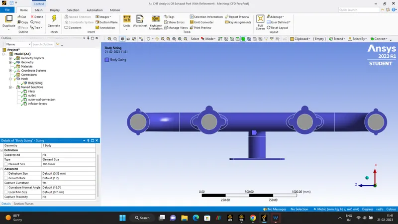
| BODY-SIZING | 100mm |
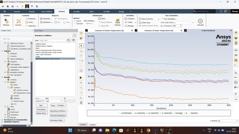
| NUMBER OF ITERATIONS | 350 |
| NUMBER OF ELEMENTS | 240000 |
| NUMBER OF NODES | 85200 |
SIZING.
- RESULTS.
RESIDUALS
TEMPERATURE.
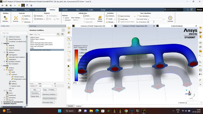
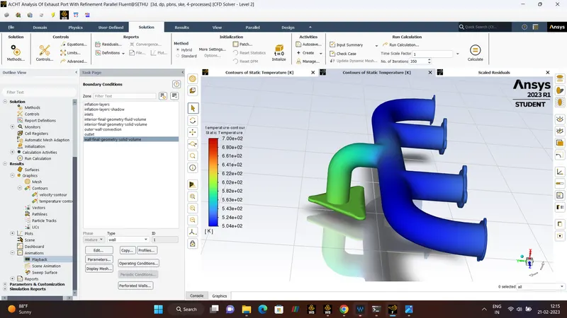
VELOCITY.
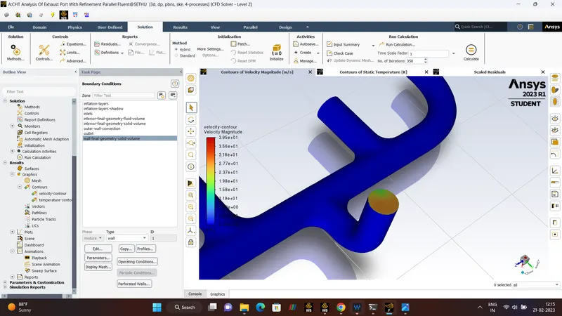
TEMPERATURE
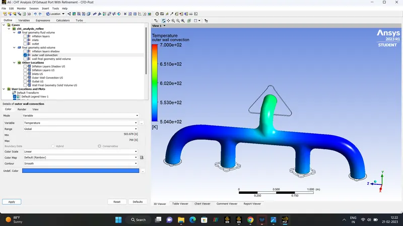
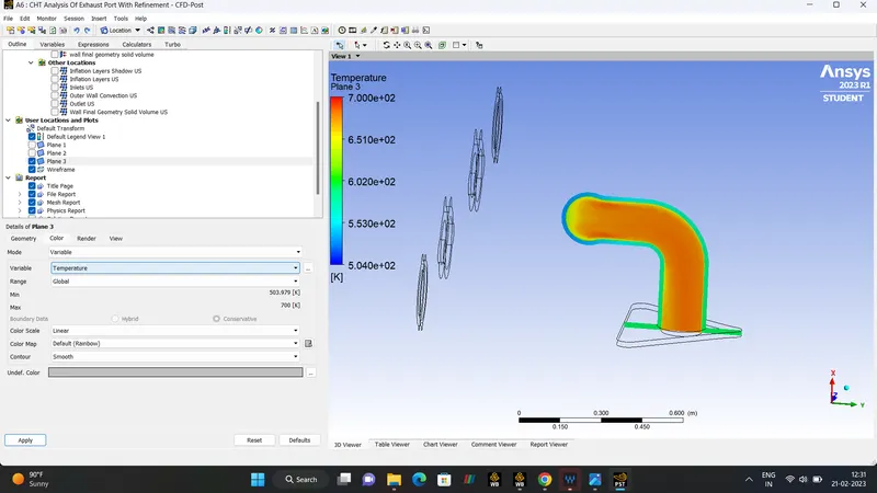
VELOCITY.
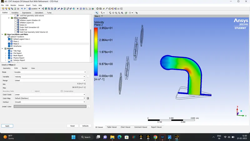
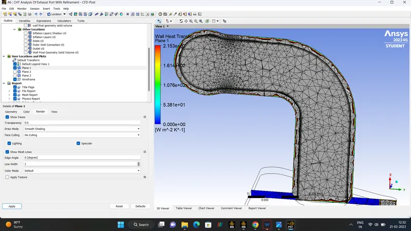
WALL-HEAT-TRANSFER.
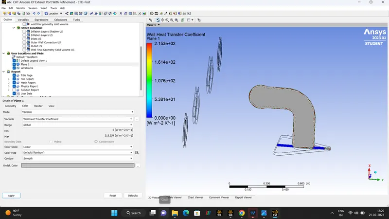
INFLATION-MESHING.
- CASE 3:- REFINEMENT.
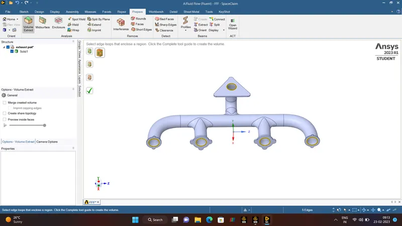
GEOMETRY.
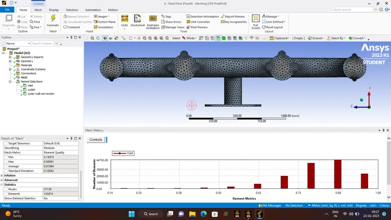
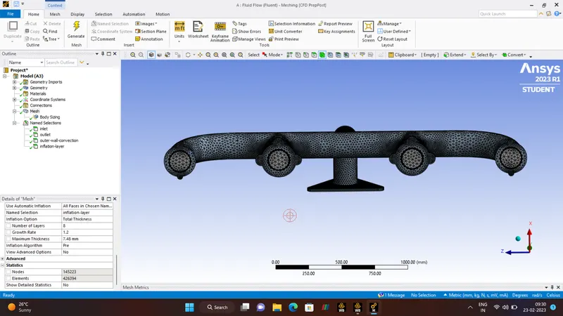
MESHING.
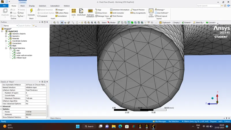
INFLATION-LAYERS.
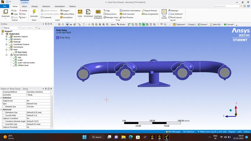
| MESH REFINEMENT | 60mm |
| INLET DIAMETER | 0.17m |
| FREE STREAM VELOCITY | 5 |
| Y+ | 30 |
| FIRST LAYER THICKNESS | 0.00174m = 1.74mm |
| NUMBER OF LAYERS | 8 |
| GROWTH RATE | 1.2 |
| TOTAL THICKNESS | 7.48 mm |
| NUMBER OF ITERATIONS | 600 |
To Calculate the Total Thickness
First-layer-thickness*(Growth-rate)^number of layers
BODY SIZING.
ELEMENT QUALITY.
SETUP.
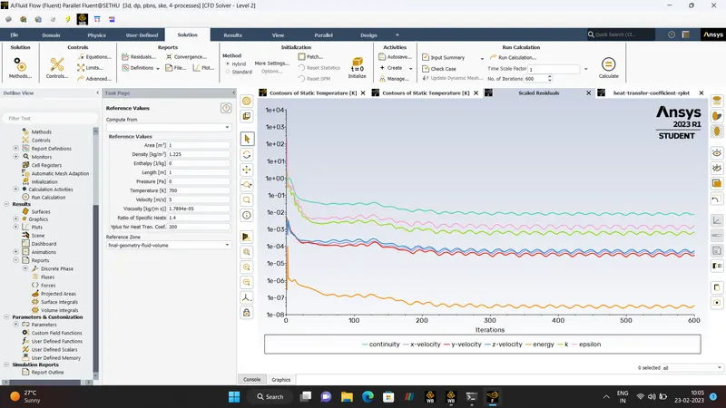
- RESULTS.
RESIDUAL.
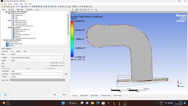
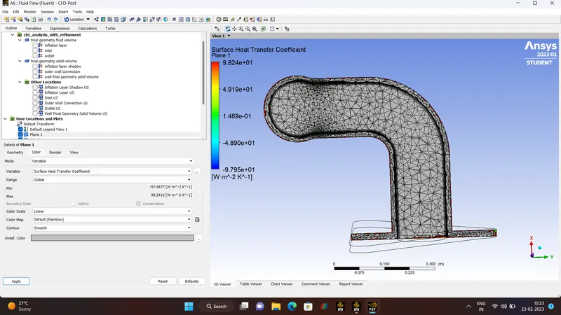
WALL-HEAT-TRANSFER-COEFFICIENT
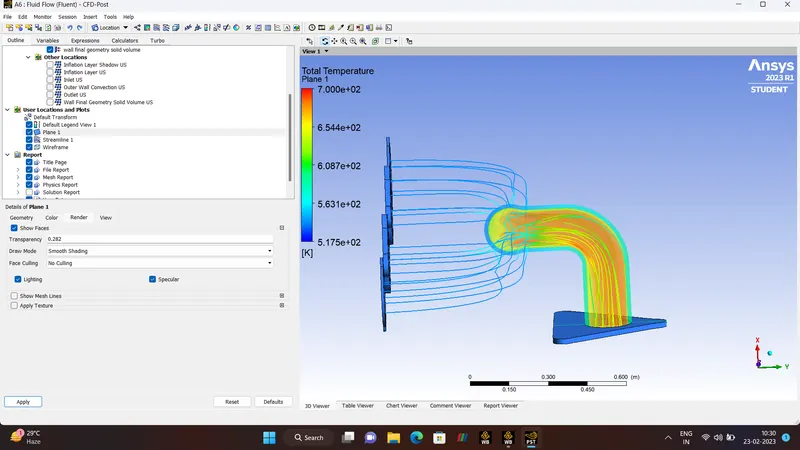
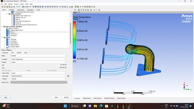
TEMPERATURE.
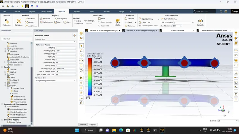
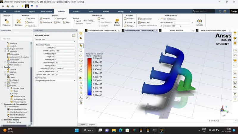
TEMPERATURE.
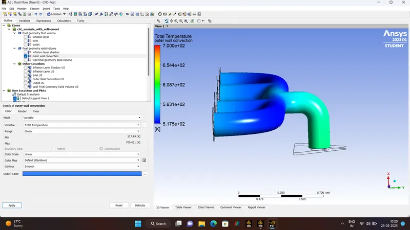
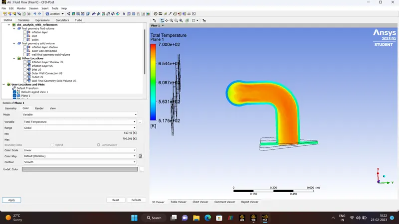
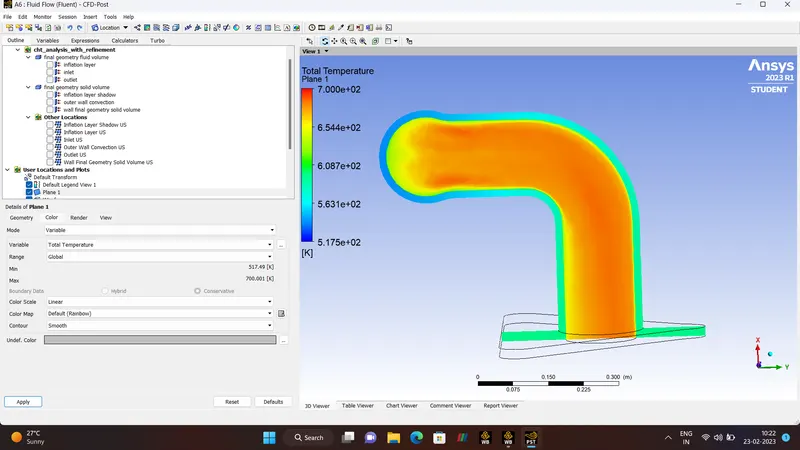
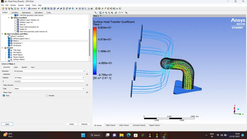
STREAMLLINE-TEMPERATURE.
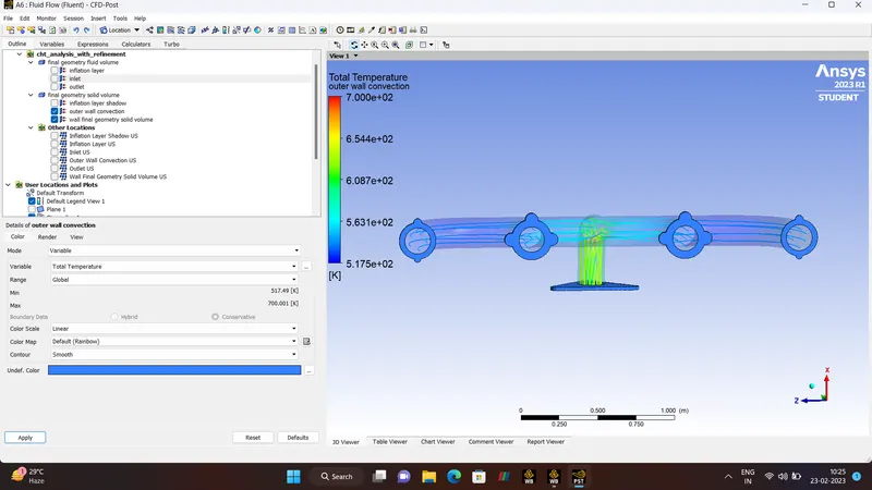
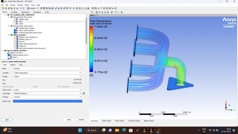
PLANE, MESH
VELOCITY.
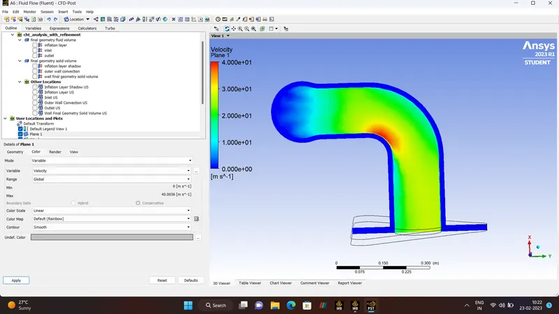
STREAMLINE-VELOCITY
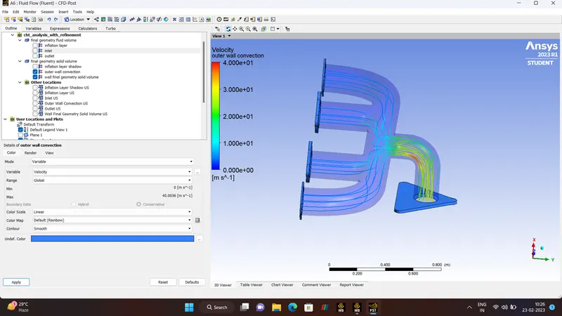
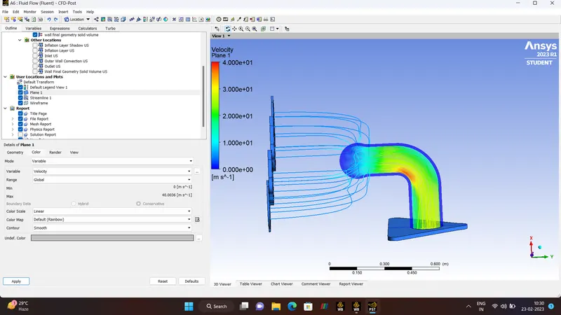
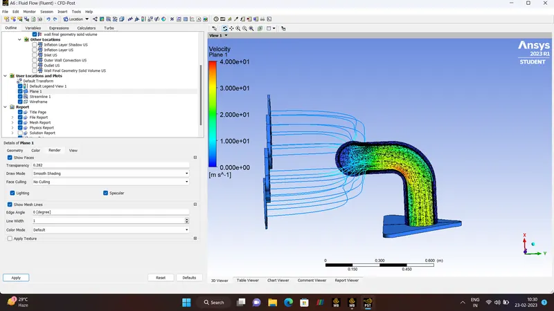
SURFACE/WALL-HEAT-TRANSFER-COEFFICIENT
ANIMATION.
- CONCULSION.
Let us come to the conclude the Conjugate Heat Transfer co-efficient of exhaust port is been is simulated by using the ansys fluent with the grid dependence test.
With the Grid Dependence(finer mesh)test the results are far better comparing to the base mesh element size and maintaining the yplus value as the flow as turbulence and hence the results are justified.
Temperature, Velocity and wall transfer co-efficient results are shown.