Week 2 Challenge : Surface meshing on a Pressure valve
- AIM:-
To Perform a Surface Meshing On a Pressure Valve Using ANSA.
- OBJECTIVE:-
To check for the geometrical errors and perform Topology cleanup accordingly. Set three different target lengths as three different cases and mesh the model.
- Target length = 1mm, 3 mm and 5 mm (i.e. 3 cases)
- Element type = Tria
Apply any one target length from the above at a time for the entire model as One case. Submit 3 different models for 3 cases.
- PROCEDURE:-
PRESSURE VALVE
A Pressure Valve or Relief Valve is type of safety valve used to control or limit the pressure in system, excessive pressure might otherwise bulid up and create a process upset, instrument or equipment failure, explosion, or fire.
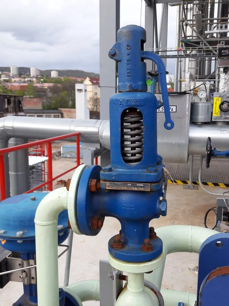
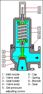
- WORKING PRINCIPLE.
Excess pressure is relieved by allowing the pressurized fluid to flow from an auxillary passage out of the system. The relief valve is designed or set to open at a predetermined set pressure to protect pressure vessels and other equipment from being subjected to pressures that exceeds the path of least resistance as the valve is forced open and a portion of the fluid is diverted through the auxillary route.As the fluid is diverted, the pressure inside the vessel will stop rising. Once it reaches the valve's reseating pressure, the valve will close. The blowdown is usually stated as a percentage of set pressure and refers to how much the pressure needs to drop before the valve reseats. The blowdown can vary roughly 2-20% and some valves have adjustable blowdowns.In High Pressure Gas System, It is recommended that the outlet of the relief valve be in the open air. In Systems where the outlet is connected to the piping, the opening of a relief valve will give a pressure build-up in the piping system downstream of a relief valve. This often means that the relief valve will not reseat once the set pressure is reached. For this system often so called differential valve is used.
- GEOMETRY
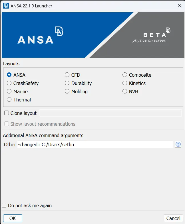
ANSA is a Computer Aided-Engineering tool for Finite Element Analysis and Computational Fluid Dynamic Analysis widely used in the Automotive Industries. It is developed by BETA CAE Systems.
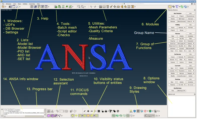
- LAYOUT.
- PRESSURE VALVE.
To do a Surface Meshing on a Pressure Valve, First step is to Import the CAD Model of Pressure Valve respectively. Once the CAD model is imported in the ANSA, most important thing is to check the SINGLE CONS! , If SINGLE CONS is there then need to clean it, to do that TOPO-CLEAN UP is done.
TOPO CLEAN-UP `rarr` Sets up tools for Geometry Clean up and then setting up the PIDs.
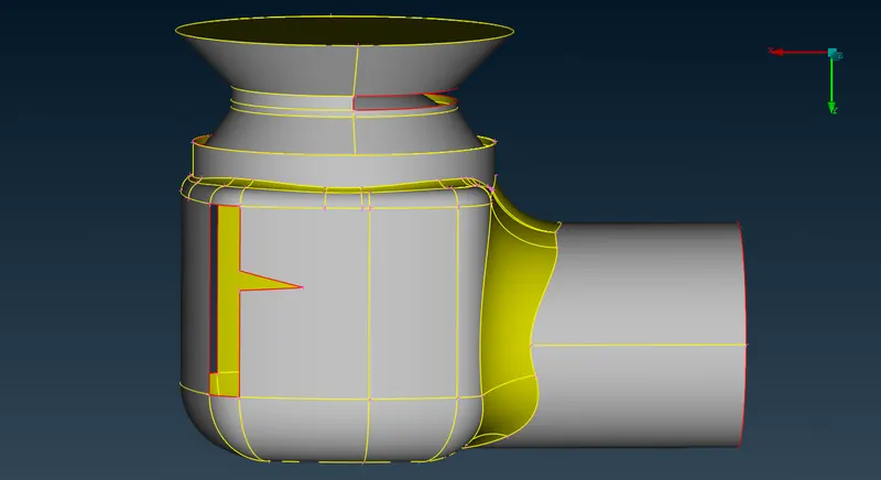
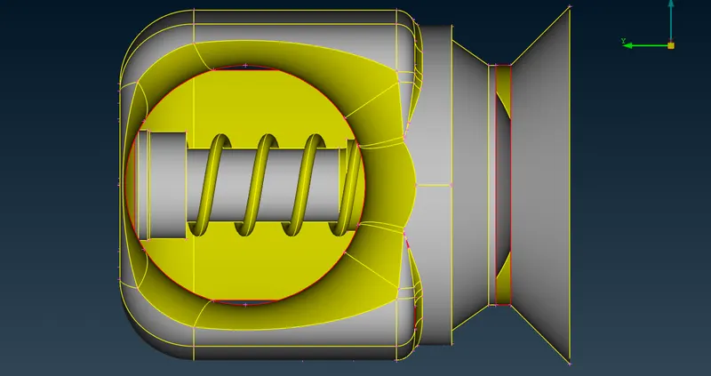
- GEOMETRY CHECK-UP
ERRORS - 46.
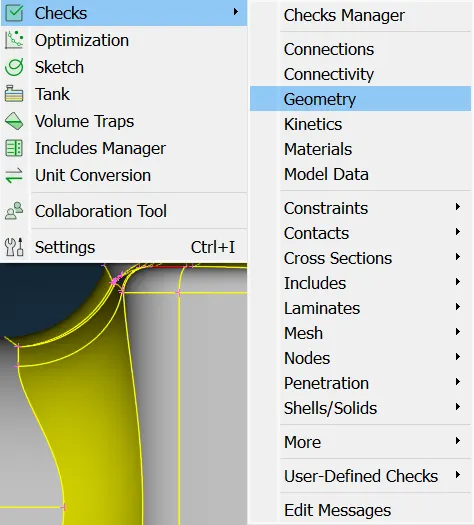
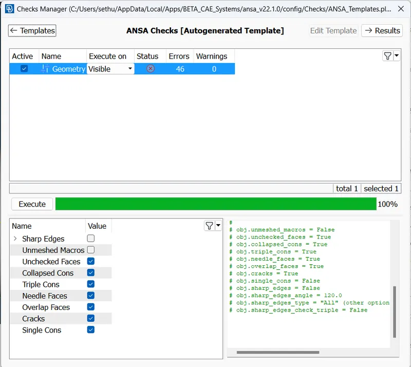
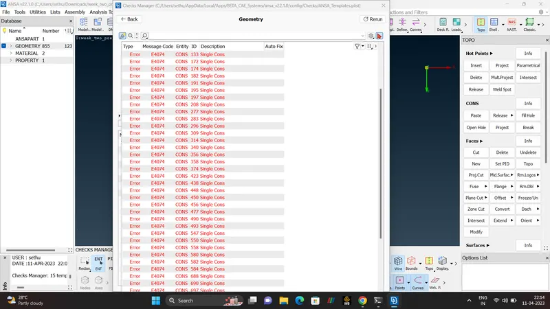
- SINGLE CONS.
The edges in ANSA is called as CONs. Single cons are highlighted in the Red Color, Double Cons are in Yellow color. Triple Cons in Blue Color.
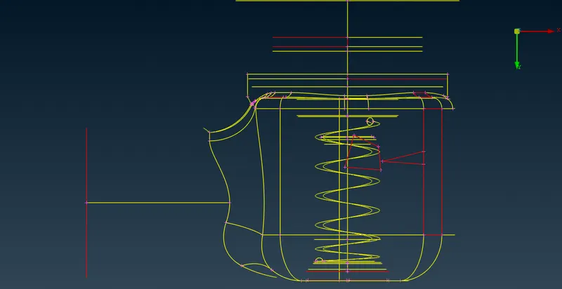
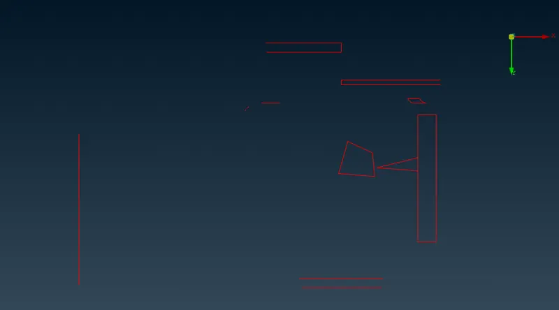
- CROSS-HATCH
This allows the visualisation of Green lines along the center isoparameteries of the faces. Cross-hatch also used to select the green lines.
- COMMANDS.
OR `rarr` OR is used to Isolate the Surfaces.
AND`rarr` It is Used to retrive the Connected Surface.
NOT`rarr` NOT is similar to OR which is used to isolate the Surface but, need to double click the surfaces.
ALL `rarr` ALL is used to retrive the all the hidden Surfaces of the Geometry.
LOCK`rarr` LOCK is used to lock the Present Geometry.
PID `rarr` PID is a Property ID which is Used to set the Boundary Conditions in the CFD.
ENT `rarr` ENTITIES refers to Face, POINT, Curves, MESH ELEMENTS, etc.
- FACES
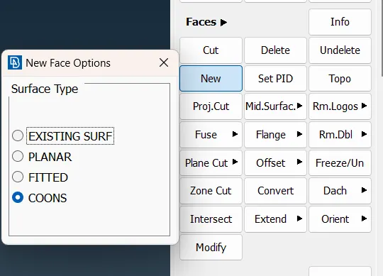
There are Four Types of FACES.
EXISTING SURFACE
PLANAR
FITTED
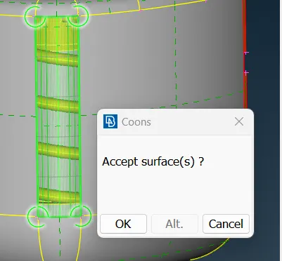
COONS
- COONS.
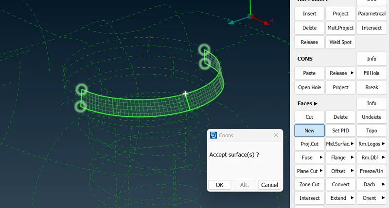
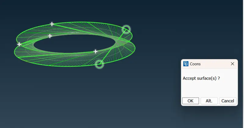
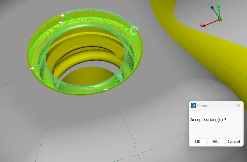
Coons patch, is a type of surface patch to smoothly join other surfaces together, and in computational mechanics applications, In CFD, Used to mesh problem domains into elements.
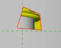
- BEFORE.
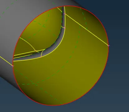
- AFTER.
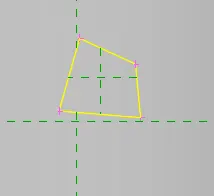
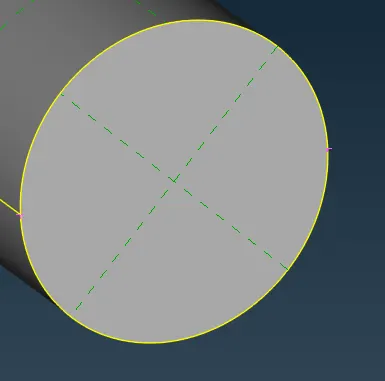
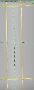
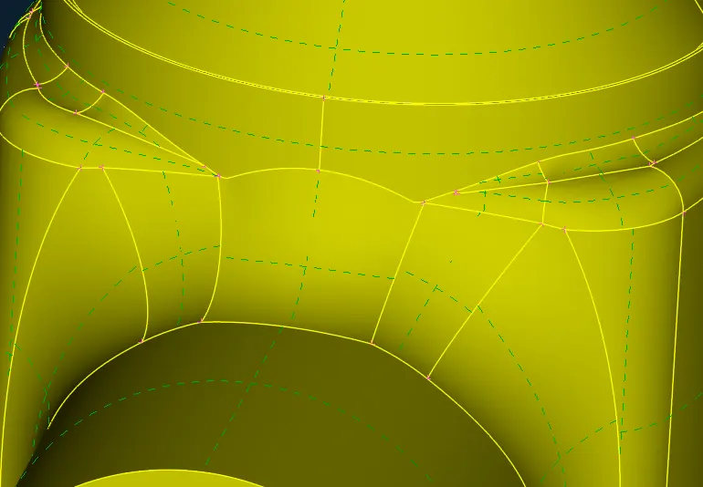
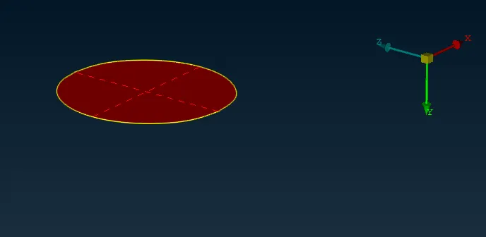
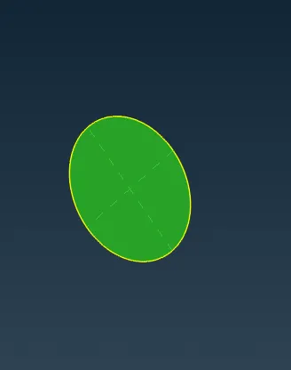
In Base Surface, we can able to see that COONs shows In correct Shape. we need proper VERTICAL SHAPE.
- ERRORS.
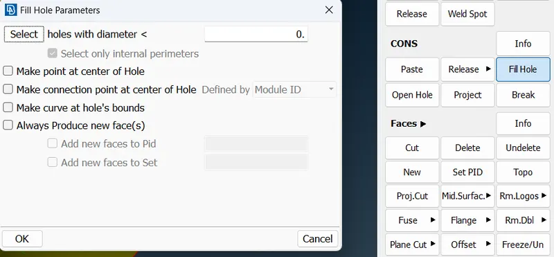
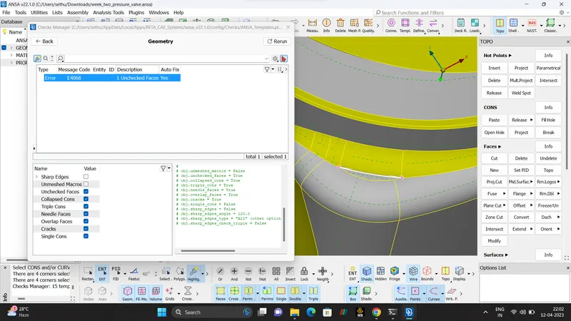
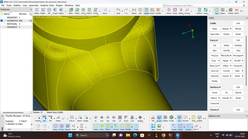
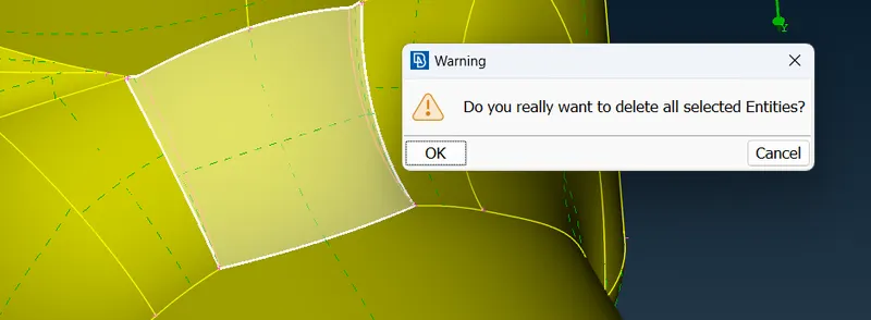
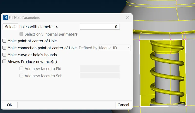
ONE Unchecked ERROR FOUND. To rectify this is error, DELETE tool is used to delete the surface then FILL HOLE command is used to FILL the DELETED surface that way error is been CORRECTED.
- ASSIGNING THE PIDs.
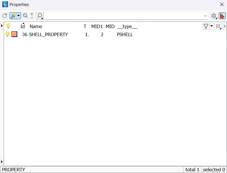
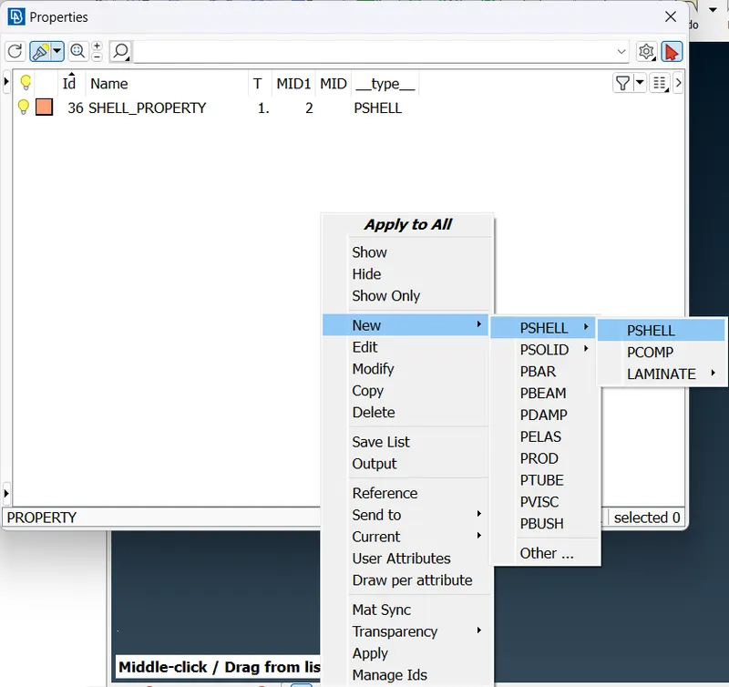
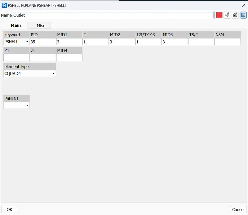
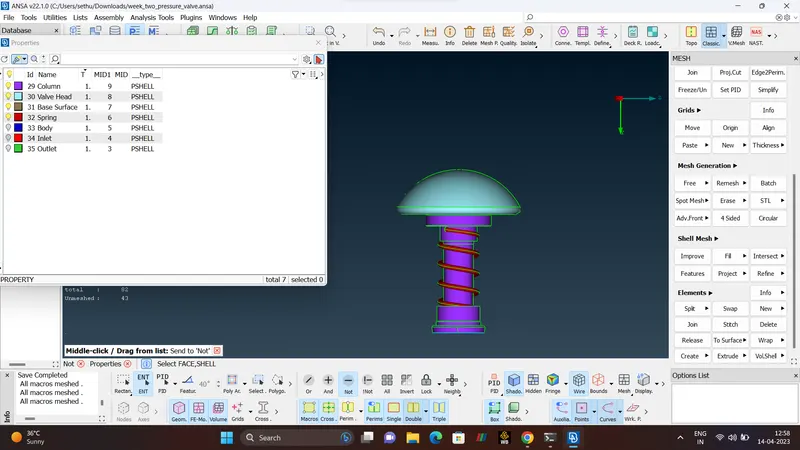
To assign the PIDs open the property menu then create NEW`rarr`PSHELL `rarr`NAME IT.
BOUNDARY CONDITIONS.
- INLET
- OUTLET
- BODY
- BASE SURFACE
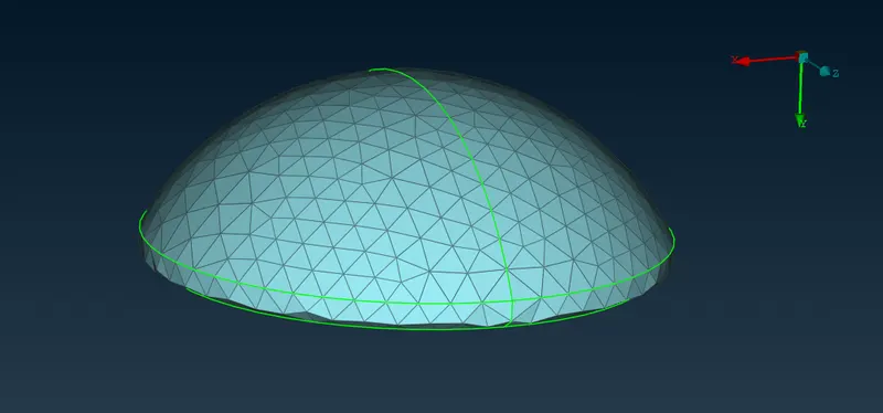
- HEAD VALVE
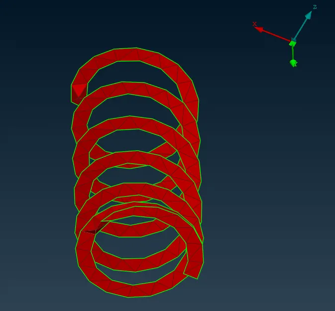
- SPRING
- COLUMN.
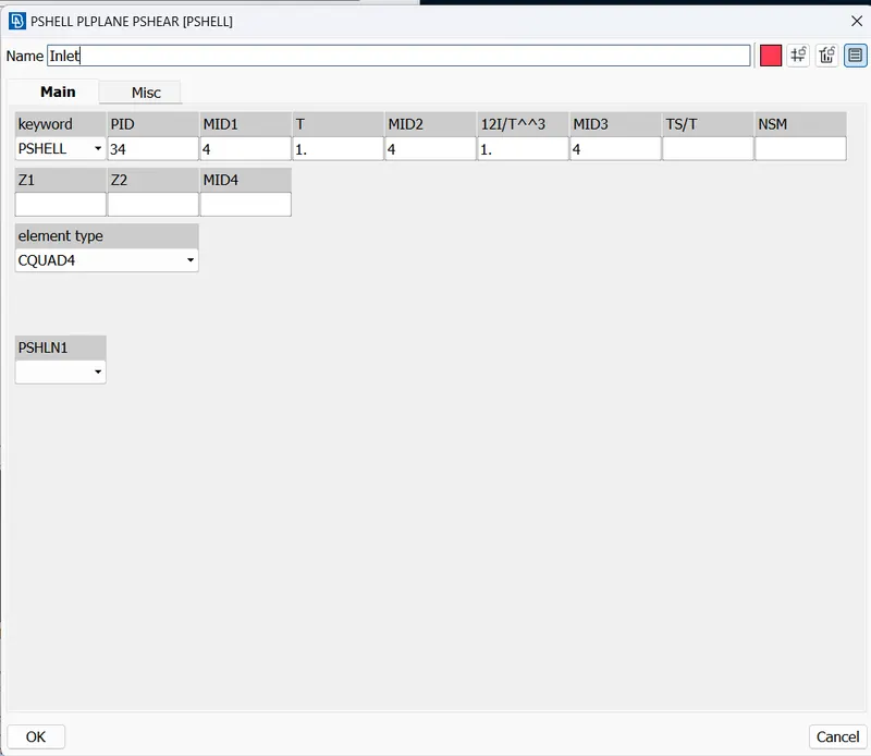
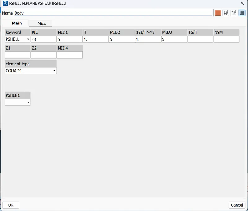
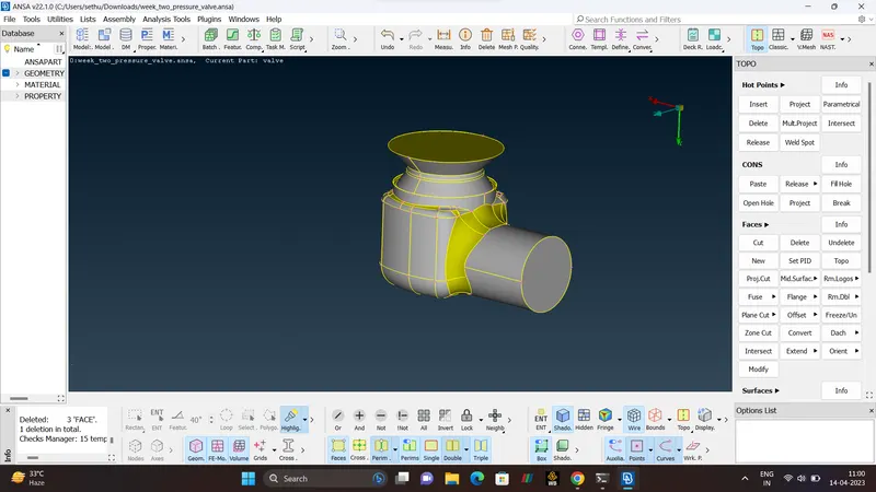
After Assigning the PIDs, we can able to see that Geometry is in mixed Color (YELLOW & GRAY) which indicates Positive and Negative. In this model yellow indicates the negative and gray indicate the positive we changing the outer surface by yellow. ORIENT tool is used.
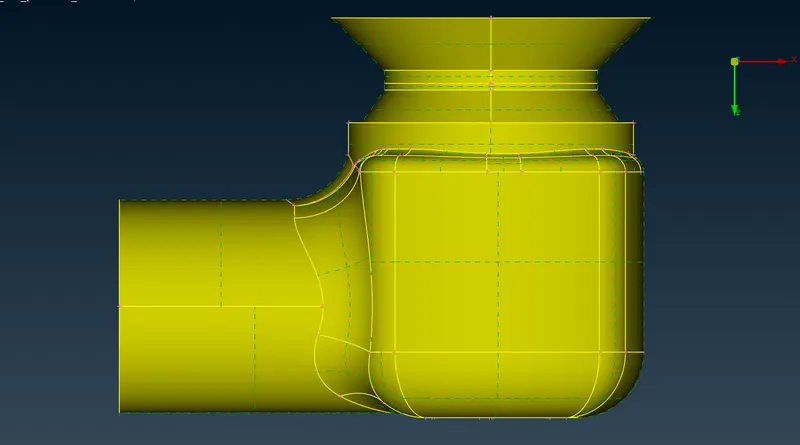
Now, After assigning the PIDs need to delete the Empty Name(SHELL PROPERTY), To delete that first need to check the UNDELETE Option whether there is an Deleted surfaces or not, if deleted then need to undo. In the geometry we can clearly able to see that OUTLET surface is GLITCHING,need to delete.
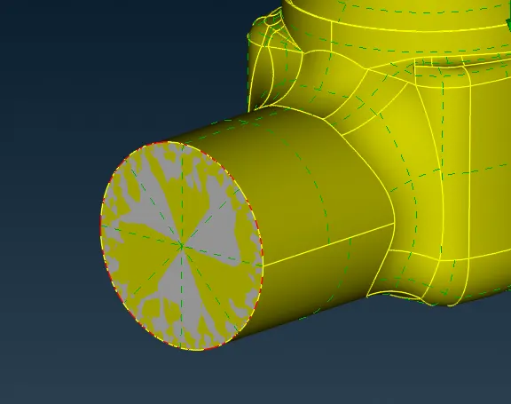
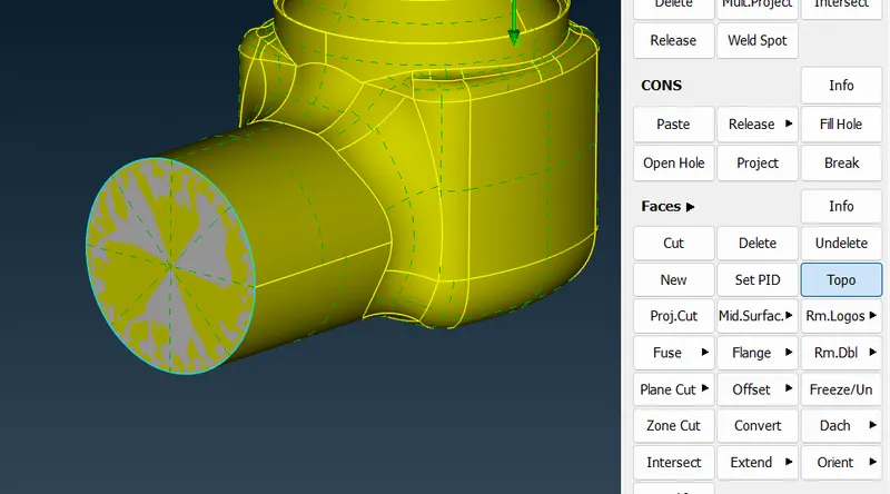
NOW, the SHELL PROPERTY is been DELETED.
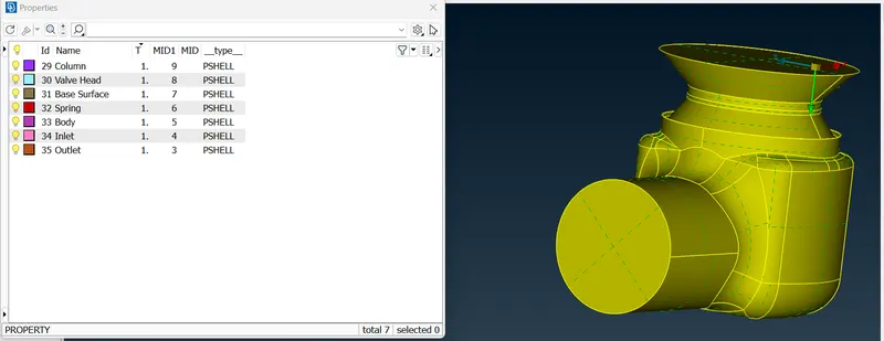
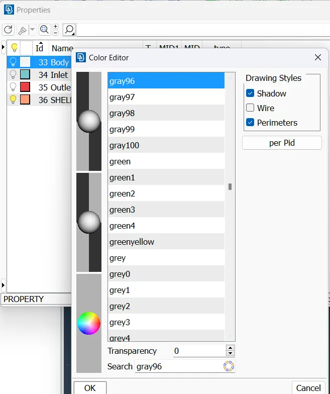
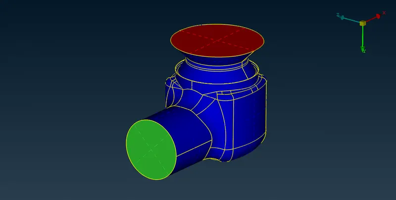
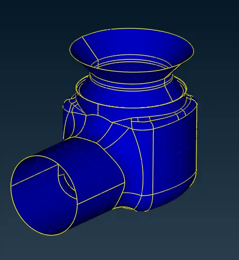
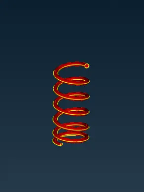
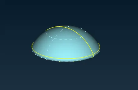
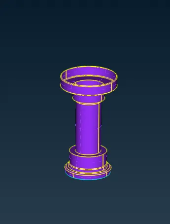
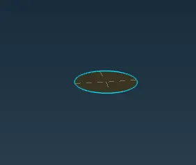
Specifying the COLORS for the respected geometry.
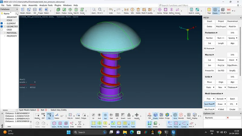
- MESHING.
A Mesh is a network that is formed of cells and points. It can have almost any shape in any size and is used to solve the PDEs (Partial Differential Equation). Each cell of the mesh represent an individual solution of equation which, when combined for the whole network, results in a solution for entire mesh.
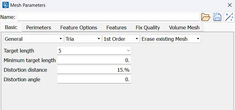
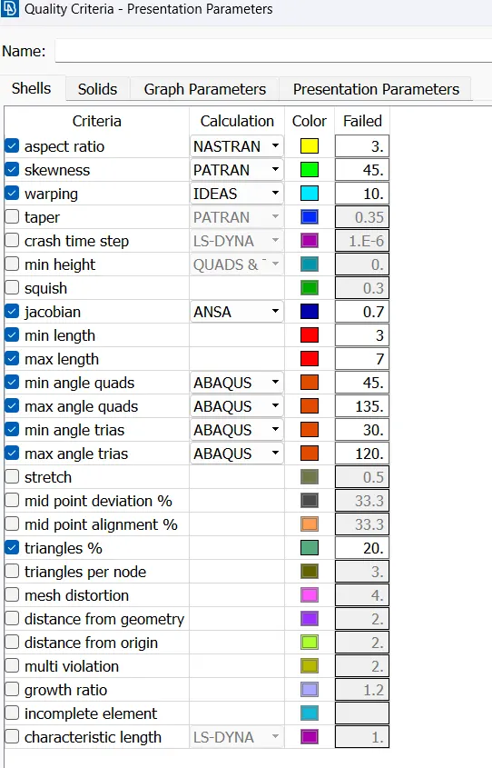
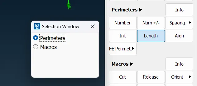
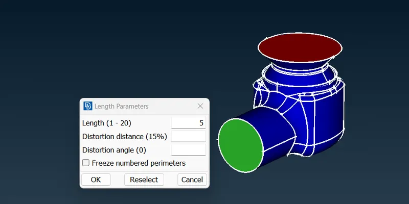
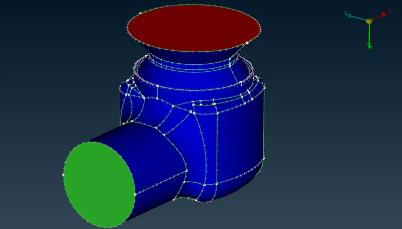
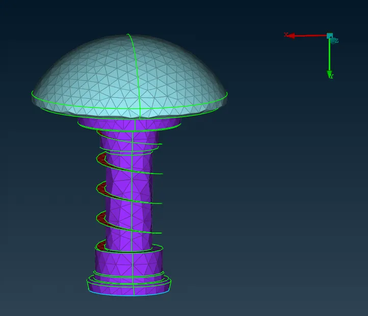
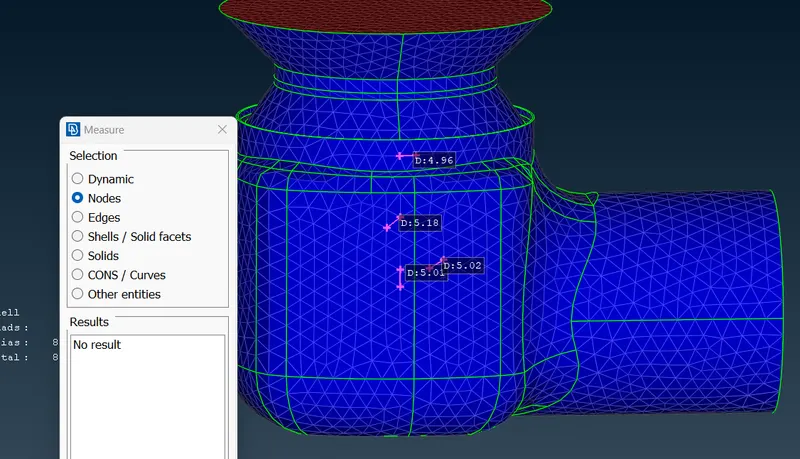
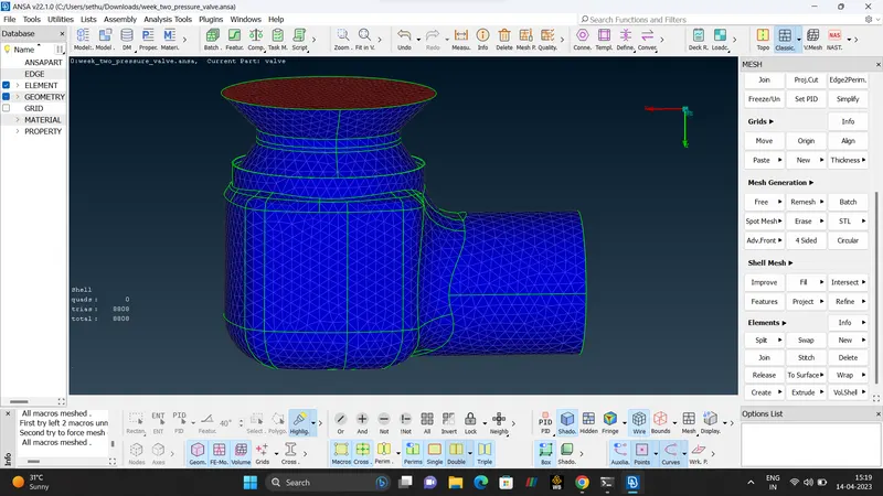
- CASE 1.
MESH TYPE - TRIA.
MESH SIZE - 5mm
MININUM LENGTH -3mm
MAXIMUM LENGTH -7mm.
- CASE 2.
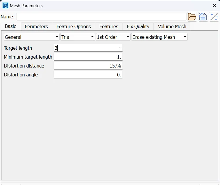
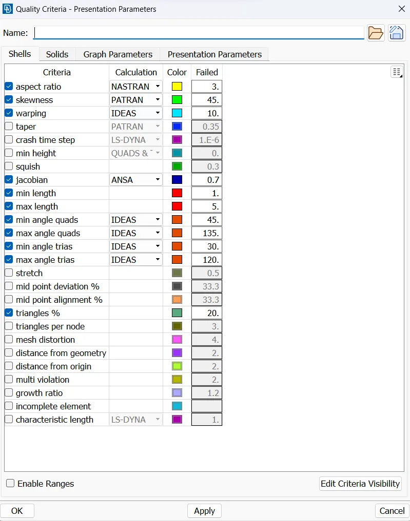
MESH TYPE - TRIA.
MESH SIZE - 3mm
MININUM LENGTH -1mm
MAXIMUM LENGTH -5mm.
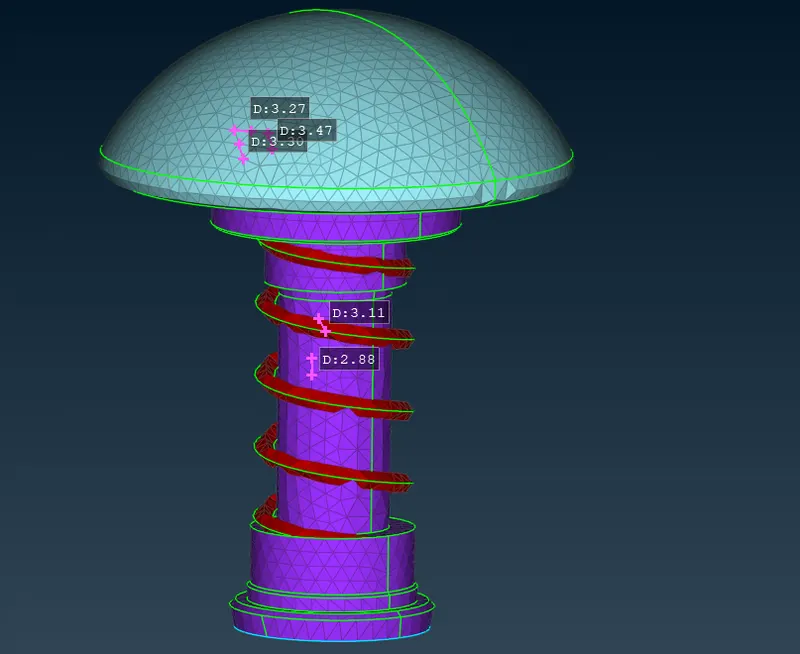
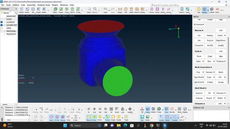
- CASE 3.
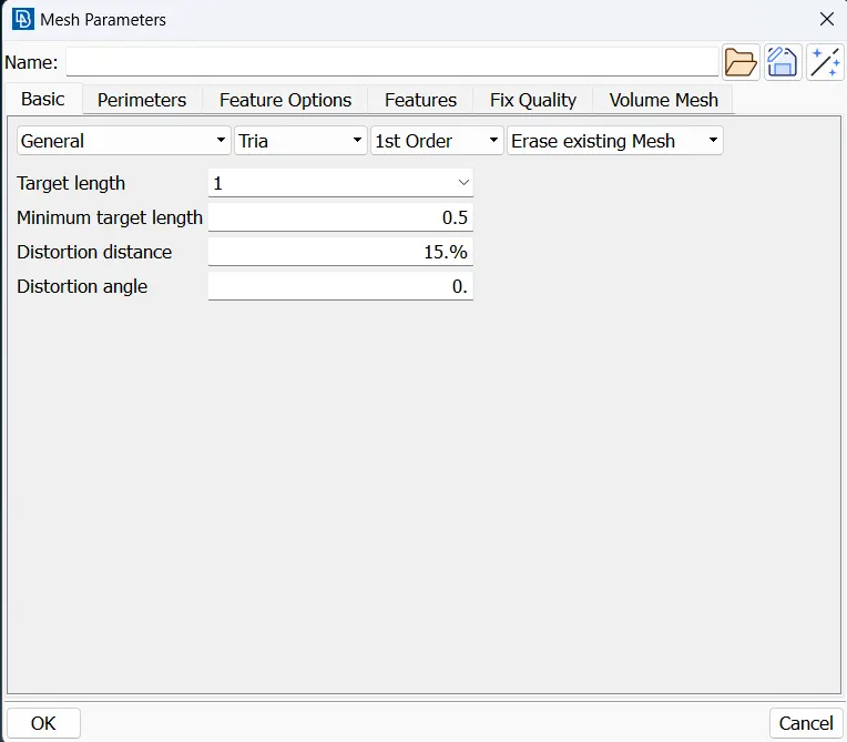
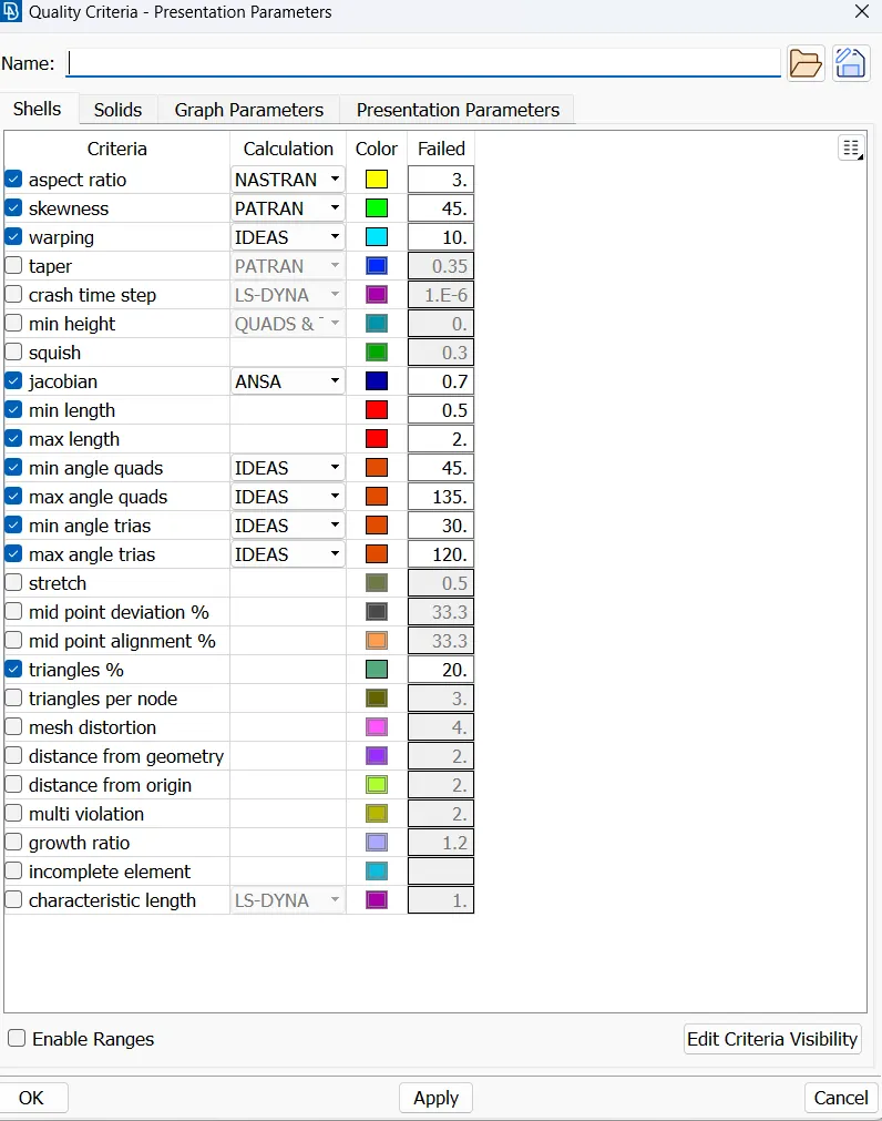
MESH TYPE - TRIA.
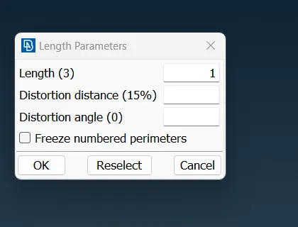
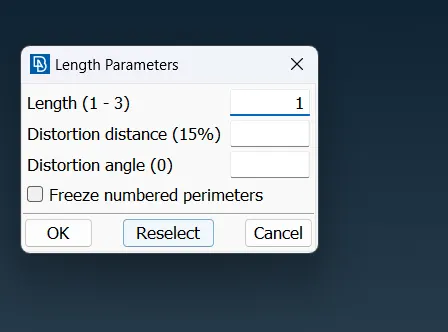
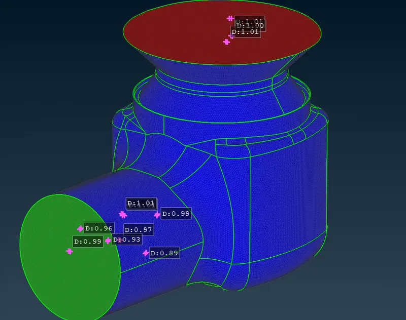
MESH SIZE - 1mm
MININUM LENGTH -0.5mm
MAXIMUM LENGTH -2mm.
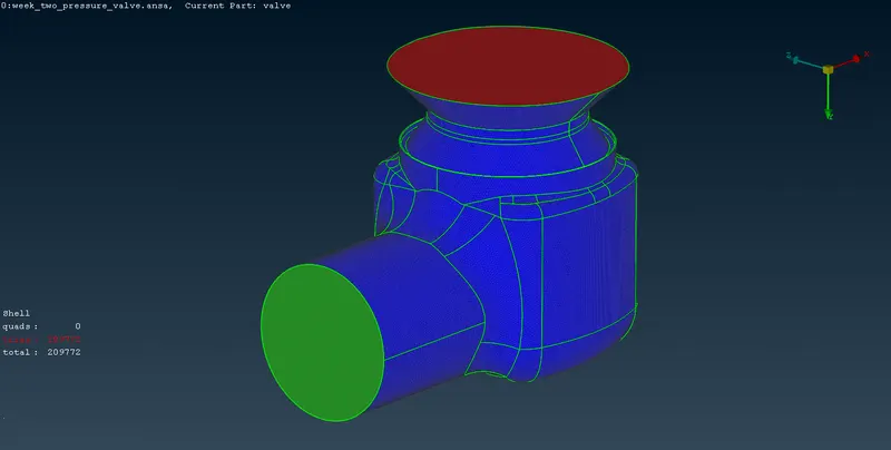
| NO | MESH TYPE | MESH SIZE | MINI LENGTH | MAX LENGTH | NUMBER OF ELEMENTS |
| 1 | TRIA (SPOT-MESH) | 5mm | 3mm | 7mm | 8808 |
| 2 | TRIA (SPOT-MESH) | 3mm | 1mm | 3mm | 23852 |
| 3 | TRIA (SPOT-MESH) | 1mm | 0.5mm | 2mm | 209772 |
- CONCLUSION.
Hence, we can conclude that Surface Meshing On a Pressure Valve is done and Satisfied.
While, Comparing the three Mesh cases that is (1mm, 3mm, 5mm) 1mm case gives that the Best Quality Mesh, but comparing with other two it takes more computational time.