Week - 4
QUESTION 1 .
AIM :
- To implement the control logic of a 'washing machine' using stateflow in a simulink model .
OBJECTIVE :
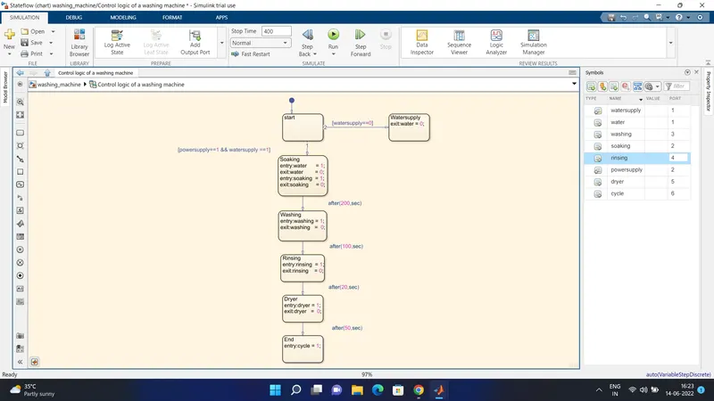
- If the power supply is available, the system gets activated .
- If the Water supply is not available, stop the process & indicate through LED.
- Soaking time should be 200s followed by Washing time of 100s.
- Then rinsing happens for next 20s & dryer runs for 50s.
- After all the process have completed turn on the finished LED.
THEORY : STATEFLOW .
- Stateflow is a control logic tool used to model reactive systems via state machines and flow charts within a simulink model.
- stateflow uses a variant of the finite-state machine notation established by David harel , enabling the representation of heirarchy , parallelism and the history within a state chart .
- stateflow also provides state transition tables and truth tables .
USES :
- Stateflow is generally used to specify the discrete controller in the model of a Hybrid System where the continous dynamics (i.e, the behavior of the plant and environment ) are specified using the simulink .
Specific applications for the stateflow includes ,
- Mode logic, where each discrete mode of a system is represented by a state .
- Fault Management , where the stateflow chart is used to control how the system reponds to the faults and failures within the system .
- Task scheduling ,where the state flow chart is used to schedule when the specific task occur , either within the stateflow chart or within the overall simulink model .
MECHANISM : WASHING MACHINE .
- Technically , this process is addressed as something called agitation .
- It is the process of improving the liquid's chemical or physical action by the employing a forced circulatory or any other periodic motion (just like stirring ) .
- In the washing machine agitation causes the clothes to move back and forth inside the washing drum that contains the water mixed with the detergent ,rubbing against each other to remove strains.
- Further cleaning is done somethng called diffusionphoresis .
- It is the spontaneous motion of the colloidal particles or the molecules in a fluid induced by a concentration gradient of a different susbtance .
- The rinsing action of washing machine clears off dirt -containing micelles ,creating a gradient of chemical concentration around the micelles that are holding on the dirt molecules stuck inside the intra yarn pores .
- Moreover , the electric field developed by the incorporating the anionic surfactants also aids the removal of dirt .
GIF OF AN WASHING MACHINE :
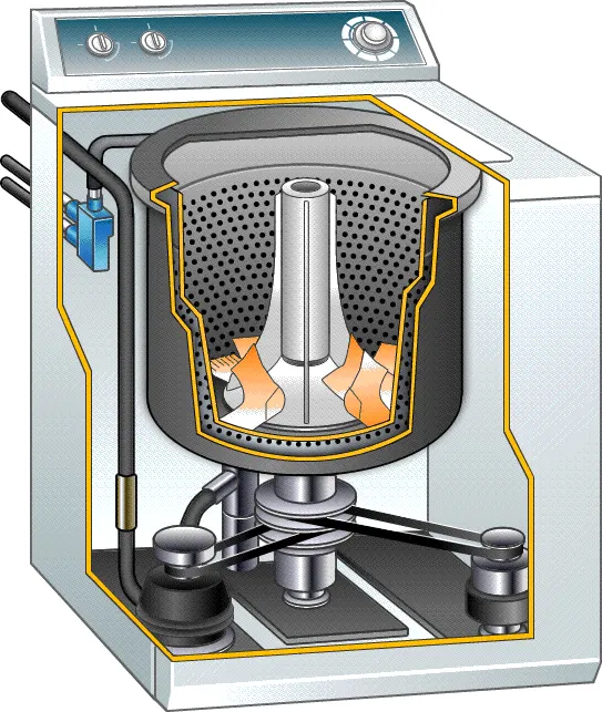
- INNER DRUM : This is where we put the laundry . one can notice that this drum rotates a bit when you touch it , and there are a lot of holes punched into it . this holes allow the water to come in and wash the clothes .
- PADDLES : These are the ridges tht lie on the edge of the drum and help move the laundry around while being washed .
- AGITATOR : It is paddle , that helps to turn the clothes around in the soapy water .
- OUTER DRUM : The outer drum is not visible when you look inside the washer , but there is another drum that holds the water while the inner drum or agitator rotates . This part is completely water - tight to pervent your machine from the leakage .
- THERMOSTAT & HEATING ELEMENT : These control the temperature of the water and heats the water to the sepcified temperature .
- PUMP : This removes the water from the drum after the wash .
- PROGRAMMER : This controls the washing machine through all the steps from washing to rinsing and spin - drying .
- PIPES & VALVES : These allow the water in and out of the washer .
MODEL :
FLOWCHART OF WASHING MACHINE :
PARAMATERS :
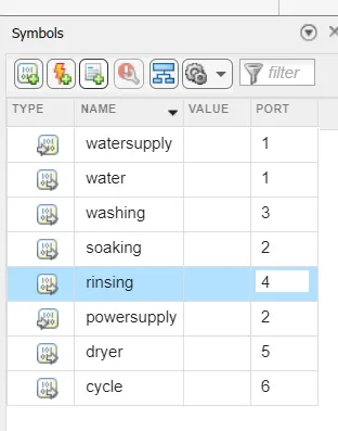
- In this case , the water supply and powersupply is given as the Input values respectively .
- water , soaking , washing , rinsing , dryer ,cycle given as a Output values in the chart respectively .
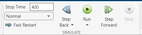
- Let us consider the total simulation run time as 400 Sec , so that it will be easily as we already have soaking , rinising , washing , dryer timing respectively .
OUTPUT :
- CASE 1 : When the water supply is OFF.
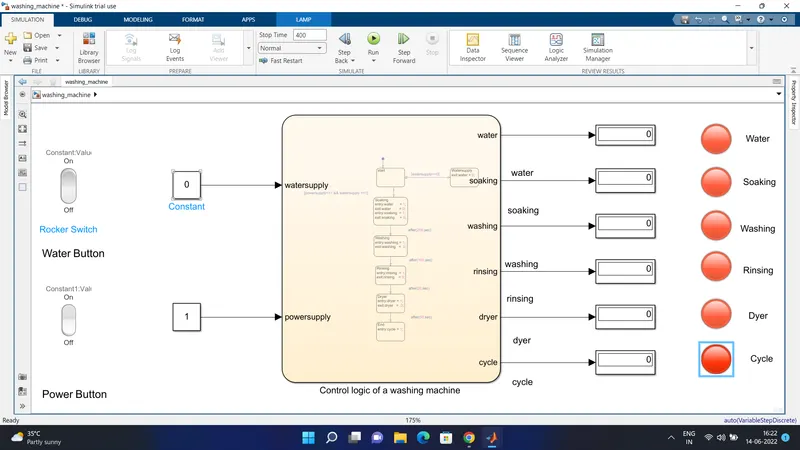
- In this case when the watersupply is OFF , power supply is ON we can clearly able to see all the LED indicator represting RED signals .
- CASE 2 : When water supply is ON .
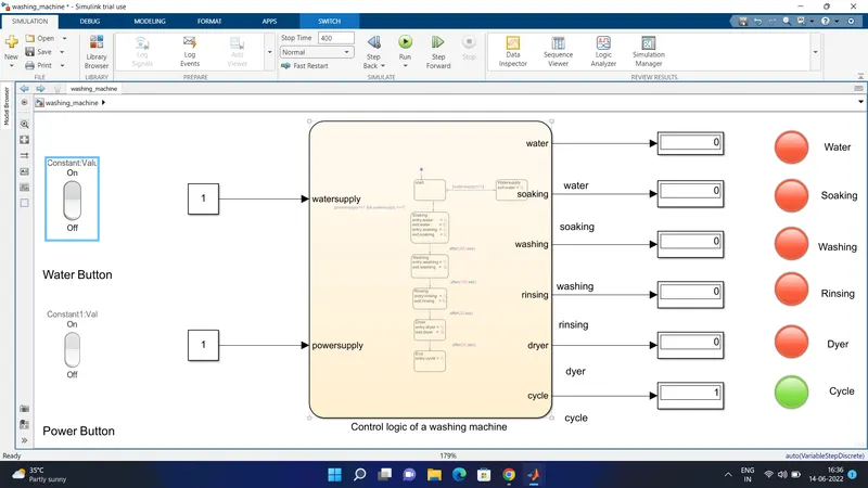
- In this final case , both the powersupply and watersupply is ON , indicating that the following step by step process has been completed and final result shows GREEN .
BLOCK EXPLANATION :
- ROCKER SWITCH : Use the Rocker Switch block to change the value of the connected variable or parameter before or during simulation.
CONSTANT : The Constant block generates a real or complex constant value signal. Use this block to provide a constant signal input. The block generates scalar, vector, or matrix output, depending on:
-
The dimensionality of the Constant value parameter
-
The setting of the Interpret vector parameters as 1-D parameter.
- CHART FLOW : A finite state machine is a representation of an event-driven (reactive) system. In an event-driven system, the system responds to an event by making a transition from one state (mode) to another. This transition occurs if the condition defining the change is true.
- DISPLAY : The Display block shows the value of the input data. You can specify the frequency of the display. For numeric input data, you can also specify the format of display.
- LAMP : The Lamp block displays a color that indicates the value of the connected signal. To configure the Lamp block to provide the information you need during simulation, specify one or more states, which pair a signal value with a color for the Lamp block to display. You can use the Lamp block with other Dashboard blocks to build an interactive dashboard of controls and indicators for your model.
CONCLUSION :
- With the help simulink , the process of simulation of a washing machine using state flow is done .
QUESTION 2 .
AIM :
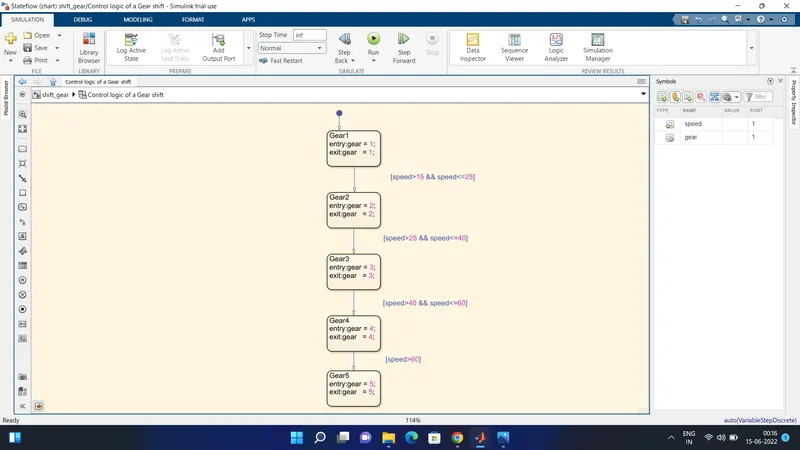
- To make a simulink chart for the Gear shift using simulink model .
OBJECTIVE :
- To create the simulink chart for the gear shift for the below mentioned parameters .
Speed Range(kmph) Gear
0 to 15 1
16 to 25 2
26 to 40 3
41 to 60 4
Above 61 5
THEORY : GEAR SHIFT.
- Gear shift mechanism includes a shaft axially moves for selecting shift planes and rotatble for engaging the gears defining shift plane .
- In this case let us consider the manual transmission .
- In vechiles with Manual transmission , the gear shifting is achieved with the help of Gear Lever.
- Gear lever can be mounted on the floor or either in the steering colunm .
- The main function of the mechanism is to engage and disengage the dog clutches with the gears .
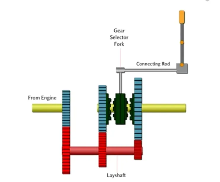
MODEL :
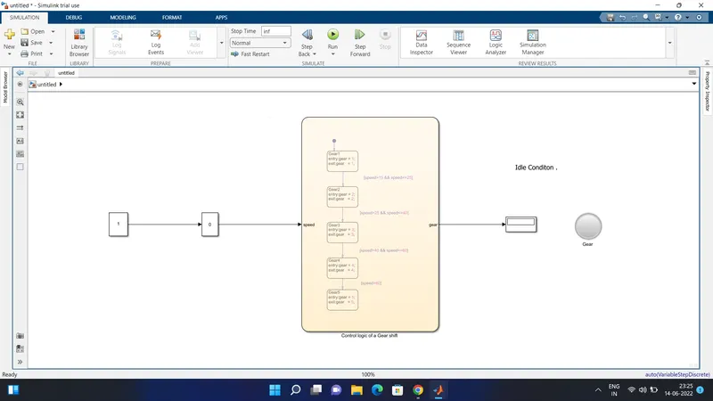
FLOWCHART OF A GEAR SHIFT :
PARAMETERS :
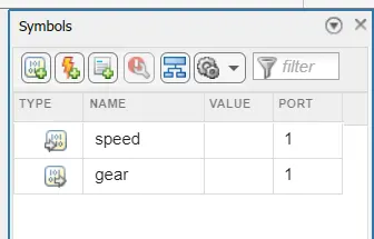
- In this case , input value of speed is 1 , output value of is gear is 1 .
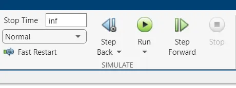
- The simulation run time take place as infinity .
OUTPUT :
GEAR 1 .
SPEED RANGE IS 0 TO 15 KMPH
.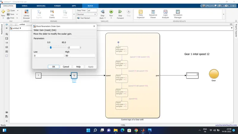 INITAL SPEED IS 12.
GEAR 2 .
SPEED RANGE IS 16 TO 25 KMPH
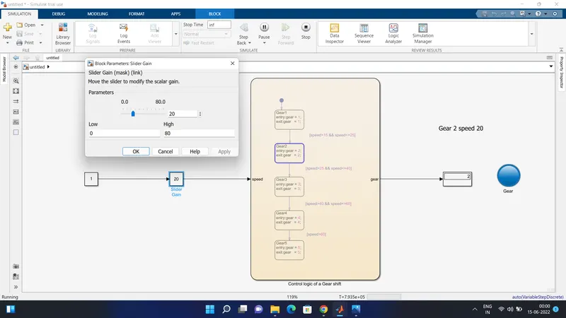 SPEED 20.
GEAR 3 .
SPEED RANGE IS 26 TO 40 KMPH
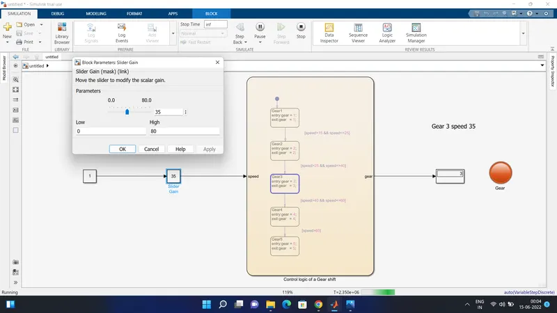 SPEED 35 .
GEAR 4 .
SPEED RANGE IS 41 TO 60 KMPH
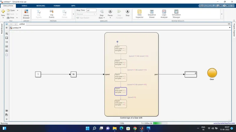 SPEED 55 .
GEAR 5 .
SPEED RANGE IS 70 KMPH
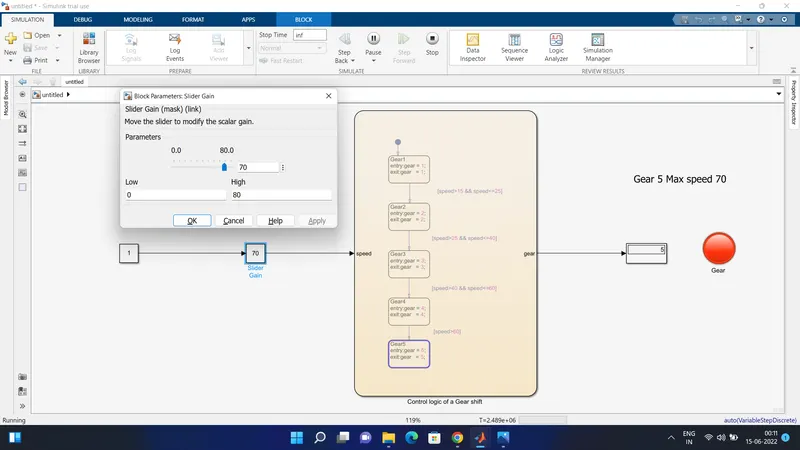 MAX SPEED 70 .
BLOCK EXPLANATION :
SILDER GAIN : The Slider Gain block performs a scalar gain that you can modify during simulation. Modify the gain using the slider parameter.
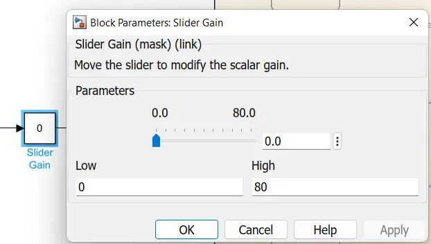
In this case the speed limit is changed from 0 to 80 kmph .
CONCLUSION :
- With the help simulink , the process of simulation of a Gear shift using state flow is done .