Project 1 : CFD Meshing for Tesla Cyber Truck
- AIM:-
To Study and Perform a CFD Meshing for Tesla Cyber-Truck Using ANSA pre-processor.
- OBJECTIVES:-
To Check and Solve the Geometrical Error Of TESLA CYBER-TRUCK Cad Model and to Assign the PIDs for given Model and to Perform a meshing with the required Target Length respectively.
- TARGET LENGTH.
Body - 3mm.
Light - 4mm.
Windows - 2mm.
Rims/Tyres - 2mm.
- INTRODUCTION.
TESLA CYBER-TRUCK
FOUNDER - ELON MUSK.
YEAR - 2019.

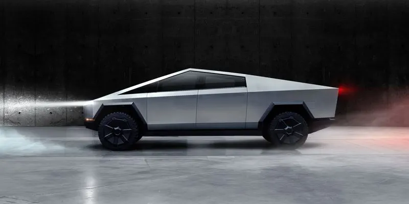
The Tesla Cybertruck is an upcoming Battery Electric Light Duty Vehicle announced by Tesla, in November 2019. Three models have been announced, with EPA range estimates of 400–800 kilometers (250–500 mi) and an estimated 0–100 km/h (0–62 mph) time of 2.9–6.5 seconds, depending on the model
Cybertruck is built with an exterior shell made for ultimate durability and passenger protection. Starting with a nearly impenetrable exoskeleton, every component is designed for superior strength and endurance, from Ultra-Hard 30X Cold-Rolled stainless-steel structural skin to Tesla armor glass. Helps eliminate dents, damage and long-term corrosion with a smooth monochrome exoskeleton that puts the shell on the outside of the car and provides you and your passengers maximum protection.Ultra-strong glass and polymer-layered composite can absorb and redirect impact force for improved performance and damage tolerance.
- COMPUTATIONAL FLUID DYNAMICS.
Computational Fluid Dynamics is the Use of applied mathematics, Physics flow and Computational Software to Visualize how the Gas or Liquid FLows, as well as how the gas/liquid effects Objects as it flow past. Computational Fluid Dynamics is Based on the Navier-Strokes Equation. CFD works on the Three Phases, they are
PRE - PROCESSING. SOLVING. POST - PROCESSING. |
- ANSA.
Automatic Net Generation for Structural Analysis.
ANSA is a Computer Aided-Engineering tool for Finite Element Analysis and Computational Fluid Dynamic Analysis widely used in the Automotive Industries. It is developed by BETA CAE Systems. ANSA tools are mainly used in Automotive Industries to mesh Plastic/Sheet metal components for CFD analysis. Tool is used for Topology Cleanup, Meshing, Improving Mesh, Assigning Thickness and Preparing Solver Deck.
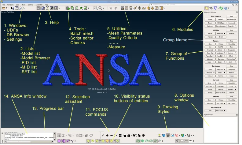
- ANSA LAYOUT.
- GEOMETRY.
In this Project CDF Meshing for a CAD Model of TESLA CYBER-TRUCK is done. To do a Meshing first step is to Import a given CAD Model of Tesla from the ANSA Spaceclaim. Once the CAd Model is Imported, the most important work is to Check the Single Cons, Triple Cons, Unwanted Surfaces are present in the given model. Then TOPO-cleanup needs to be done respectively.
- TOPO-CLEANUP.
Topology is Geometry Consisting of Surface, Lines, Edges, etc which combines together and make CAD model. Topology cleanup is a process of fixing CAD model and making it ready for meshing process.
TOPO-CLEANUP sets up tools for Geometry Cleanup and then Setting up the PIDs. Basically Our Geometry Model is in irregular Shape, including Overlapping Surfaces,CONS,etc. To Start the Topocleanup change PIDs setting into the Entity Model for better Understanding. Then Divide the CAD MODEL into Half as given geometry is in Symmetric Shape.
- CONS.
There are Three types of CONS,
SINGLE CONS
DOUBLE CONS
TRIPLE CONS.
- CONS.
The edges in ANSA is called as CONs. Single cons are highlighted in the Red Color, Double Cons are in Yellow color. Triple Cons in Blue Color.
COMMANDS.
- CROSS-HATCH.
This allows the visualisation of Green lines along the center isoparameteries of the faces. Cross-hatch also used to select the green lines.
- OR - OR is used to Isolate the Surfaces.
- AND - It is Used to retrive the Connected Surface.
- NOT - NOT is similar to OR which is used to isolate the Surface but, need to double click the surfaces.
- ALL - ALL is used to retrive the all the hidden Surfaces of the Geometry.
- LOCK - LOCK is used to lock the Present Geometry.
- PID - PID is a Property ID which is Used to set the Boundary Conditions in the CFD.
- ENT - ENTITIES refers to Face, POINT, Curves, MESH ELEMENTS, etc.
ANSAFILE `rarr` NEW `rarr` LOCATION OF CAD MODEL`rarr` OPEN.
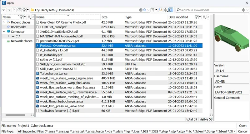
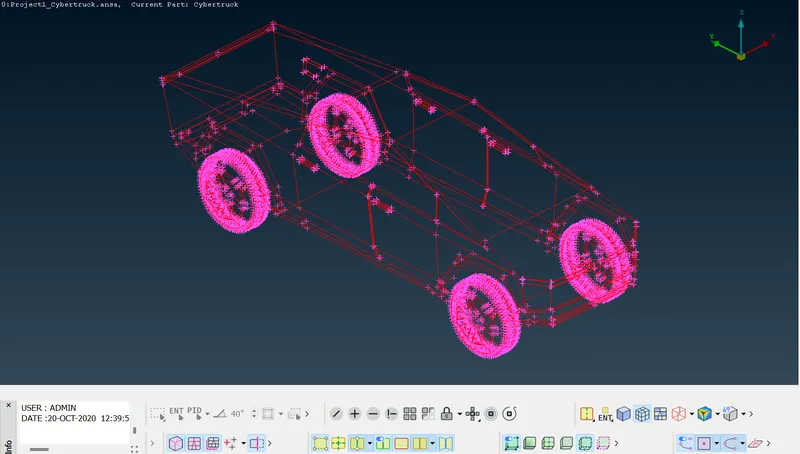
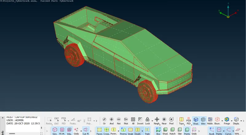
For better understanding Change it to Enitie Mode.
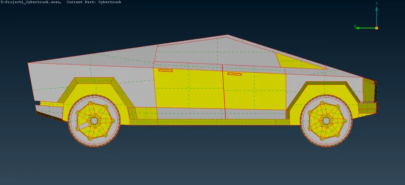
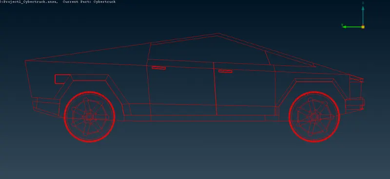
From the above images we can Clearly able to see the Single Cons present all over the Model, So Our task is to Clear those Cons. In the Face Option Click the Topo select the Model do Topo.
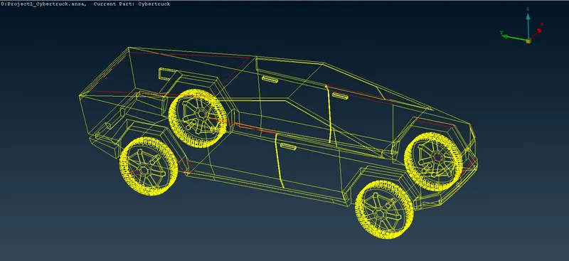
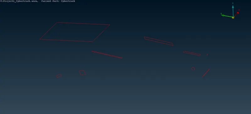
After Completing the Topo still Single Cons, then those Single Cons must be a Missing Surfaces. Before doing the Patch Work for those missing Surfaces, first we need to check the given CAD model as it will be in a Irregular in Shape. For better resolution (Finer Shape) need to do a mesh. Select Mesh Length Parameters 1mm. Now the Cad model will be in Finer Shape.
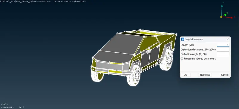
As the Tesla Cyber-Truck is in Symmetric in Shape we can delete the Half Portion of Model,in a way it will be much easier to rectify those Geometrical errors and Clear it. To Delete the Half Portion of Car we can Universal Delete. But in these case we could'nt able to use that option because it Selects Entire car. So we can Use Plane Cut Option. In FACE menu click the PLANE-CUT option select the 3 points which half portion needs to deleted, it will create the Double Cons Over that region. Then We can use either delete option in the FACE menu or Universal Delete Option.
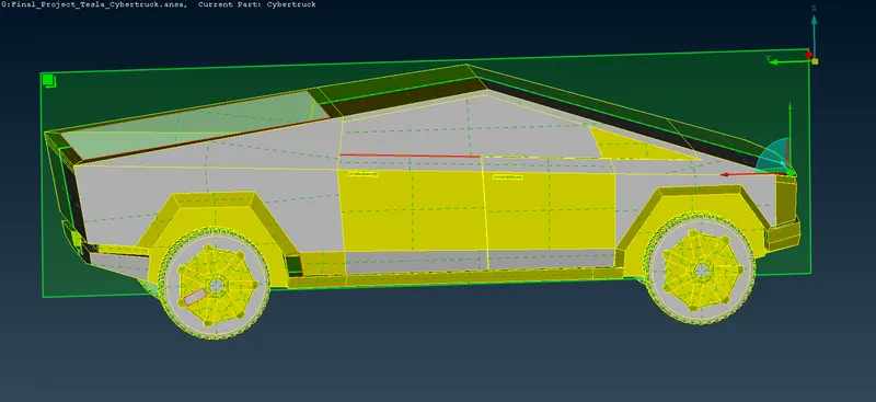
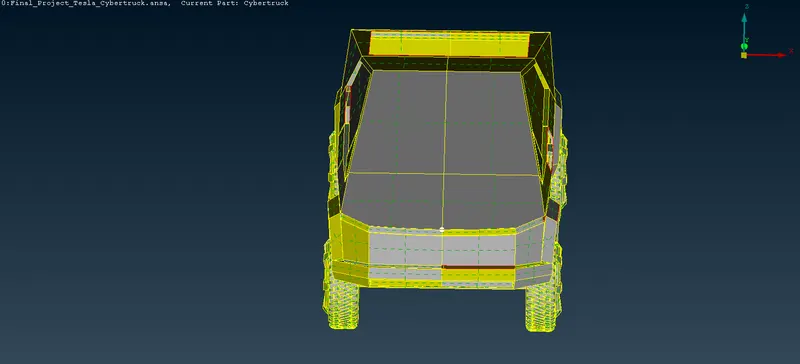
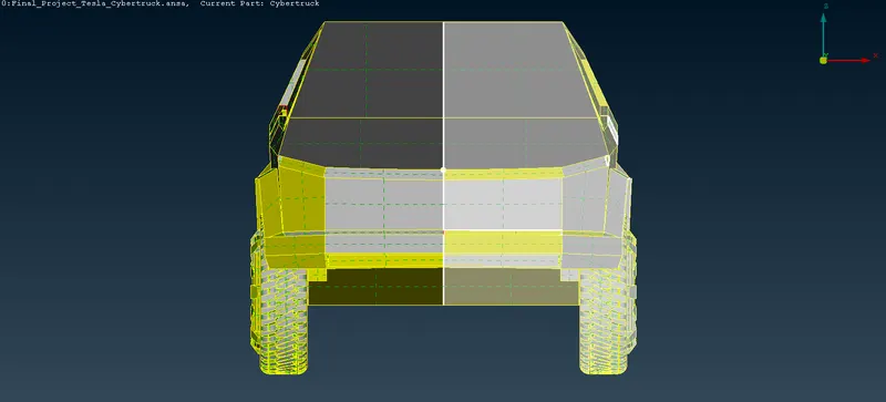
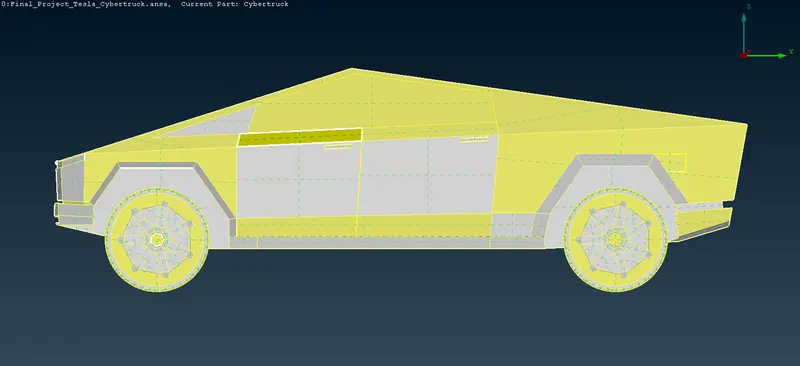
- FINAL OUTPUT.
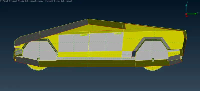
- MISSING SURFACES.
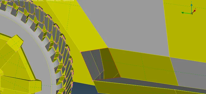
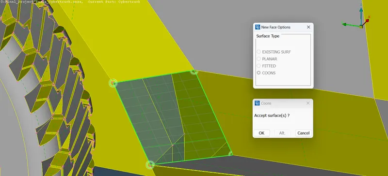
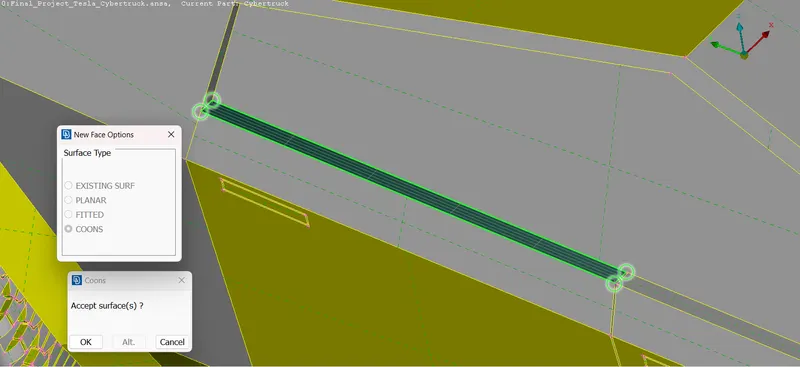
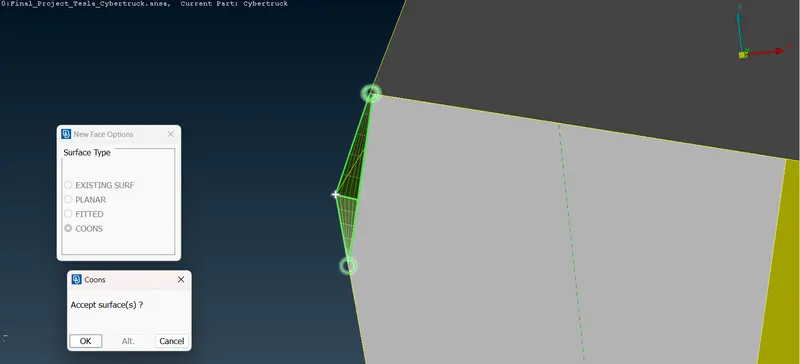
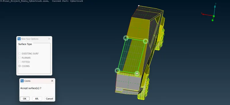
Tools Used `rarr` FACES `rarr` NEW `rarr`COONS
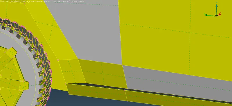
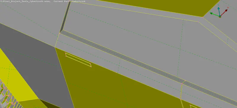
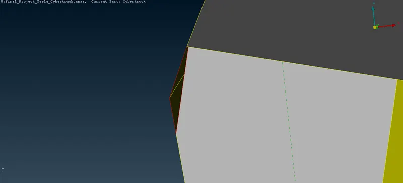
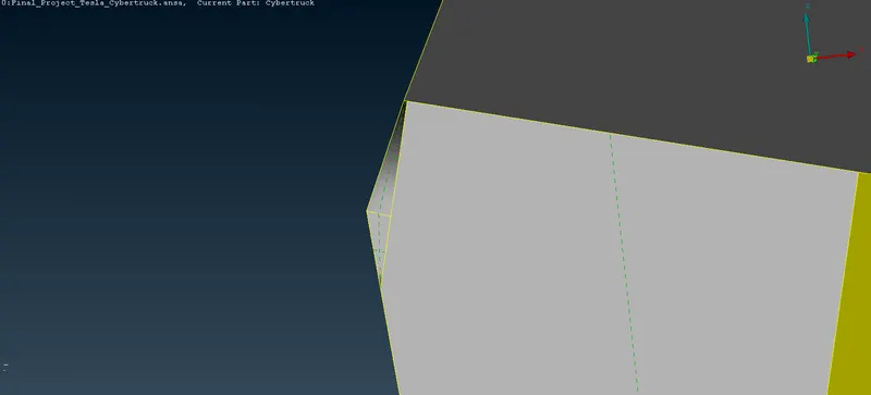
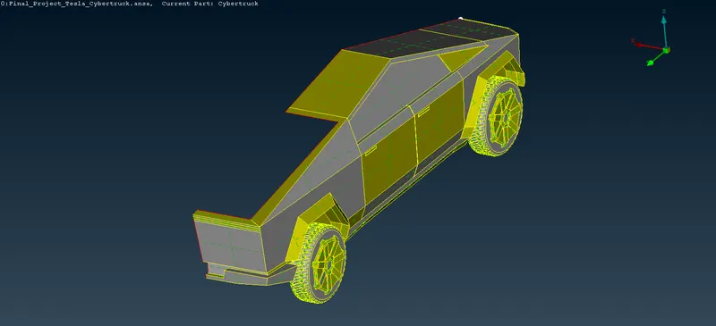
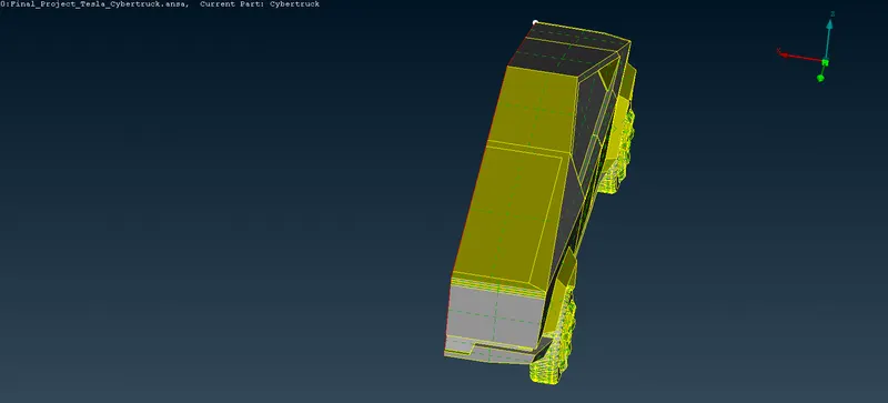
Form the below images we can able to see the Missing Surfaces from BODY, RIMS, WINSHIELD regions. Our objective is to rectify those missing surface by doing Patching those Surface, to do patch we can use COONS/FITTED on those Surfaces.
- BODY.
- OUTPUT.
BEFORE AFTER

- OUTPUT.
- WINDOWS
- OUTPUT.
- RIMS.
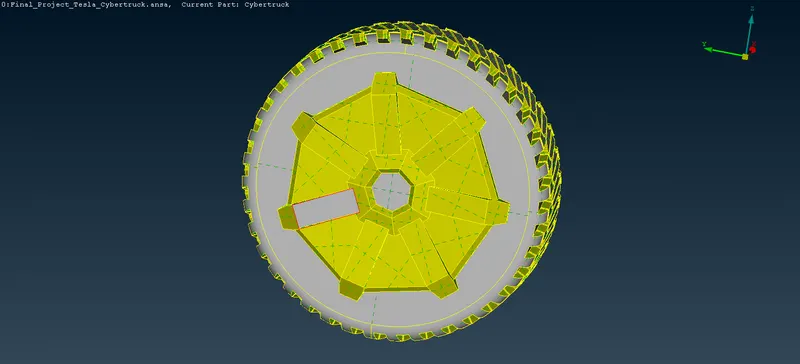

- OUTPUT.
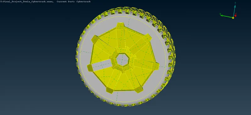
- OVER-LAPPING SURFACES & SINGLE CONS & UNWANTED SURFACES.
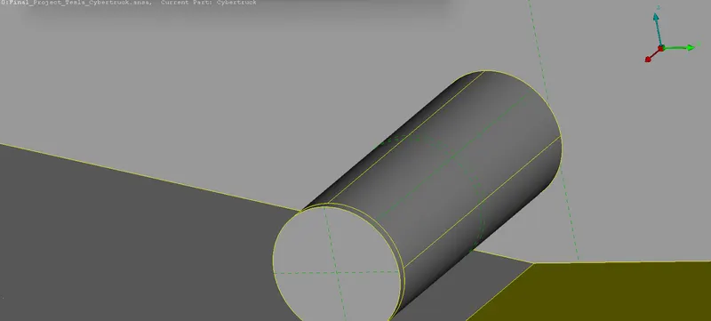
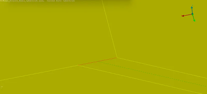
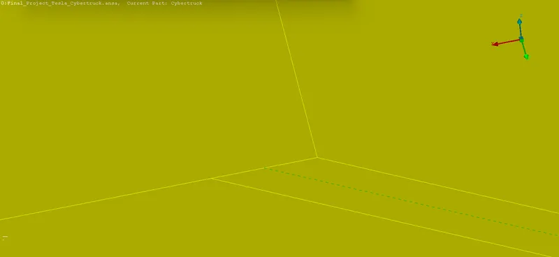
In the Above images there is an Overlapping surfaces present in the axle Shaft which is connected to the Tyres, and there is Small Single Cons also and Two Unwanted surfaces also present in inside the Body Region as need to a Create a Single Volume to do a Volumetric Meshing. Finally Cleared those Errors.
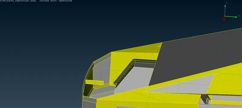
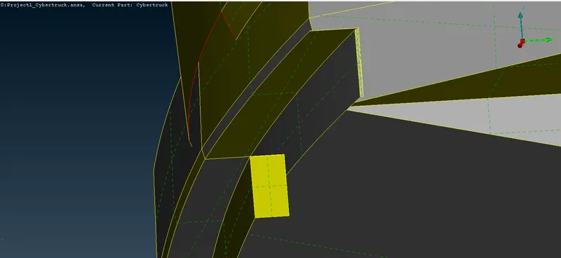
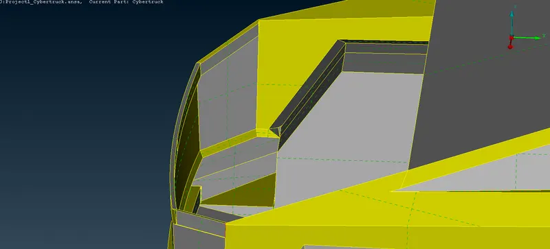
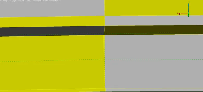
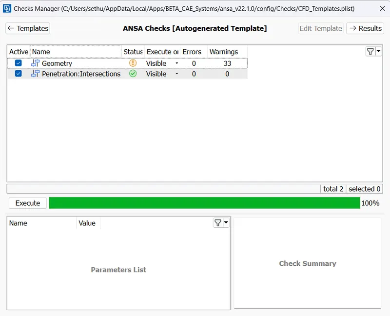
After Completing those Errors, Now again need to conform that any Single Cons, Intersection Errors is present if there need to be rectified Orelse While Meshing it creates a major Problem.
- INTERSECTION ERROR - 1.
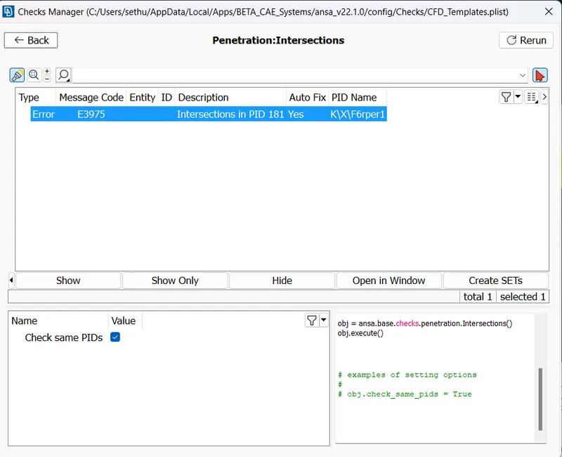
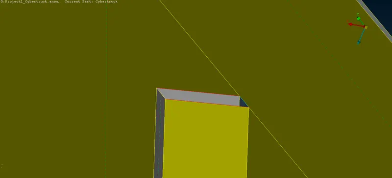
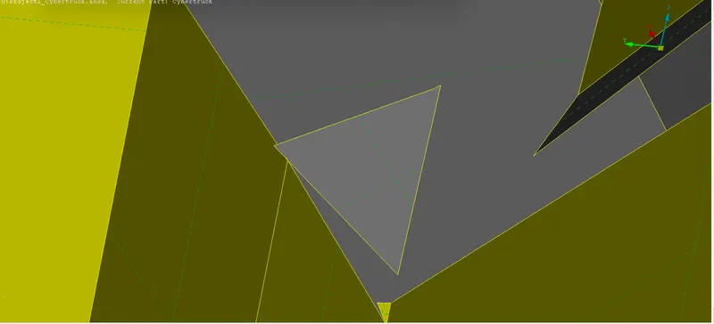
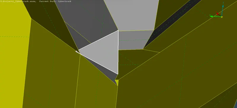
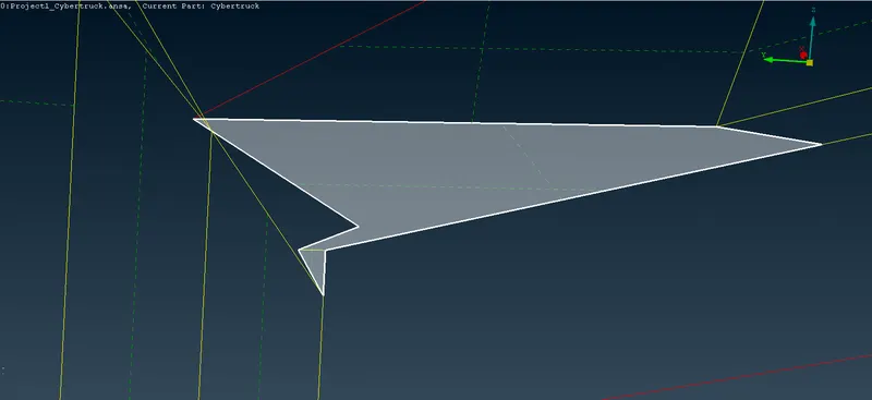
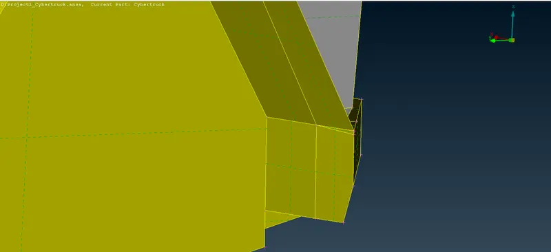
As we expected there is an Intersection errors in the Tyre (shaft) regions and Body Region.
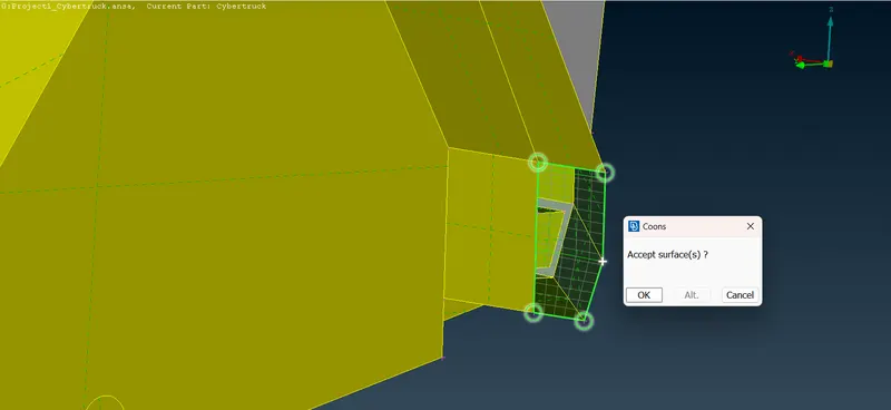
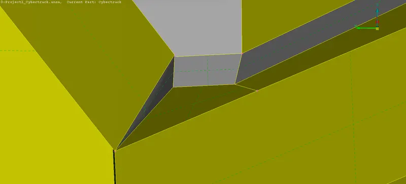
- BODY REGION.
With the Universal Delete Option delete the Intersection/Unwanted Surfaces. Then Patch it with help of Coons Options.
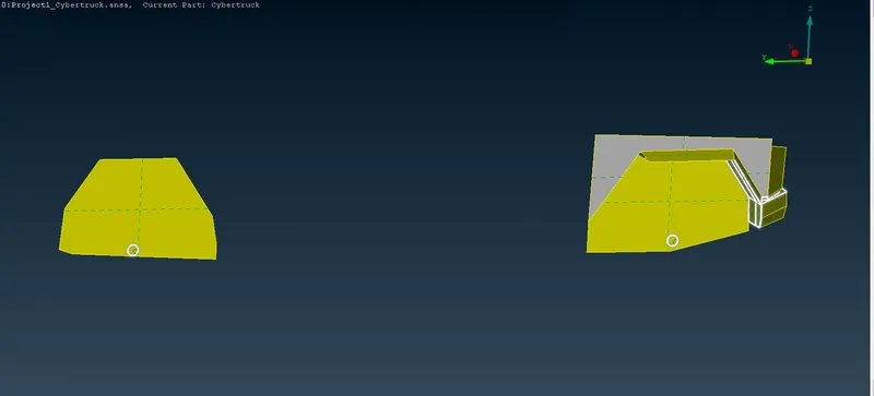
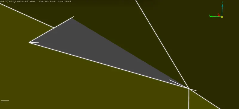
- FINAL OUTPUT.
- INTERSECTION ERROR - 2.
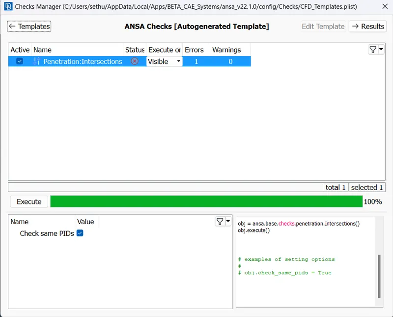
These intersection Error is between the Tyres and Small axle Shaft, to rectify these type of errors PROJECT Option is used. Project the Single Cons of the respected Shaft, then select the remaining body and shafts Triples Cons will be formed, Now we can Delete the Outerside of the Shaft.
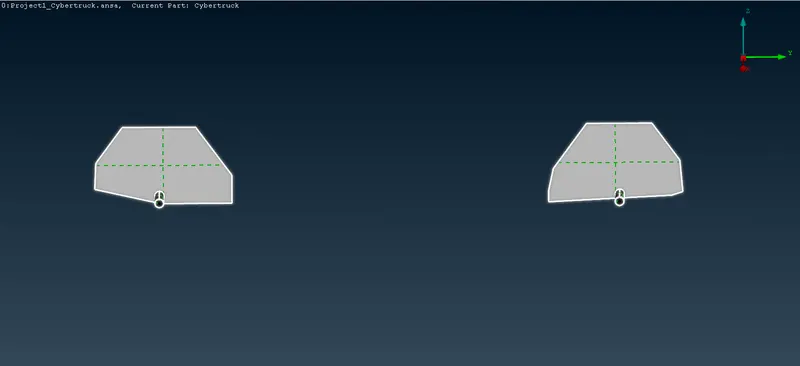
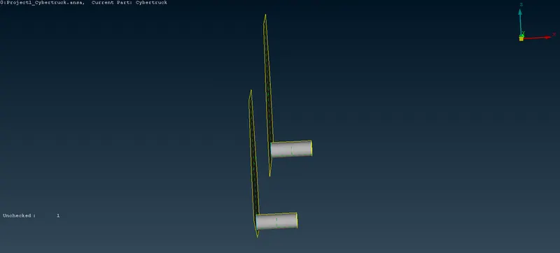
- OUTPUT.
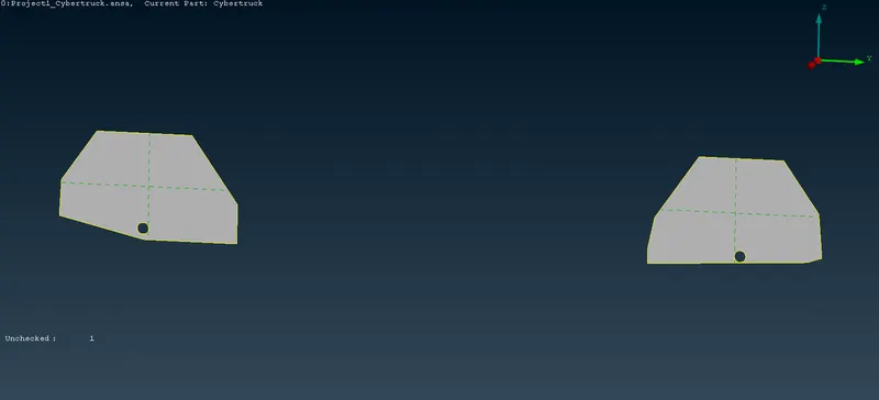
- FINAL OUTPUT.
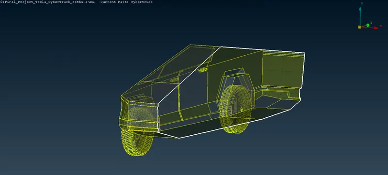
- BOUNDARY CONDITION.
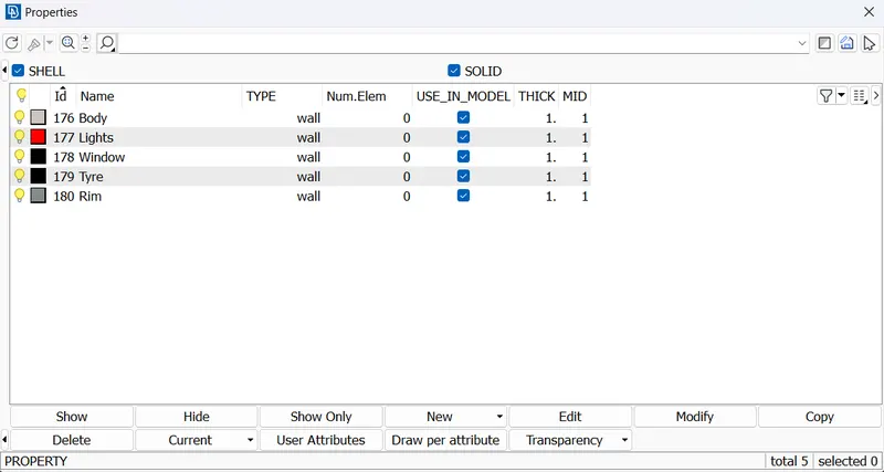
Assigning PIDs.

BEFORE AFTER
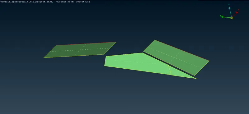
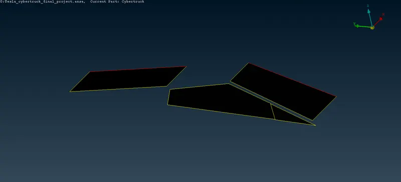

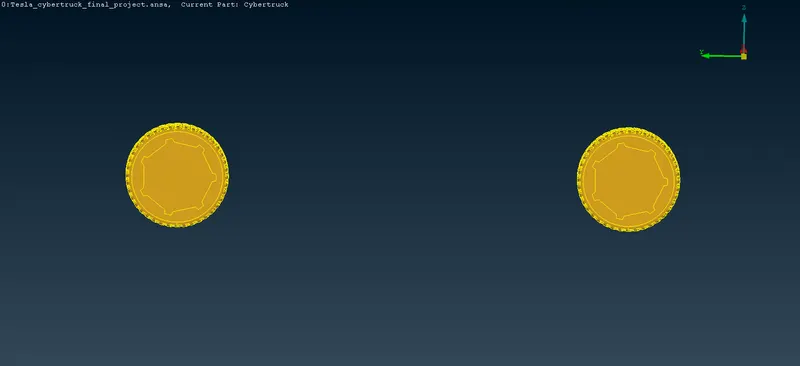
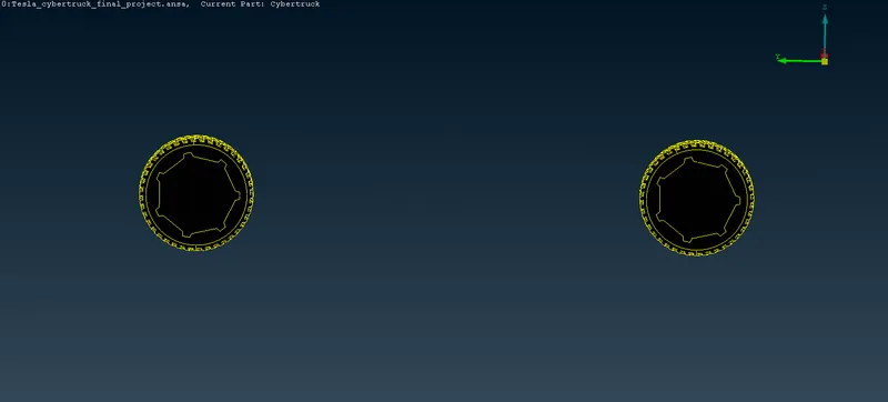

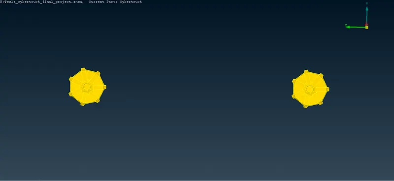
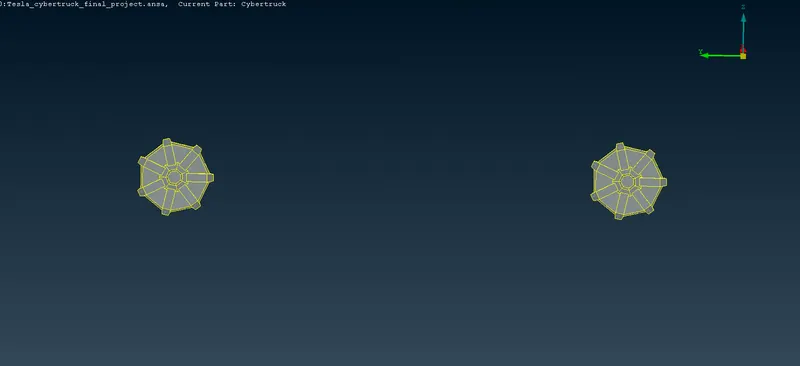

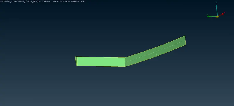
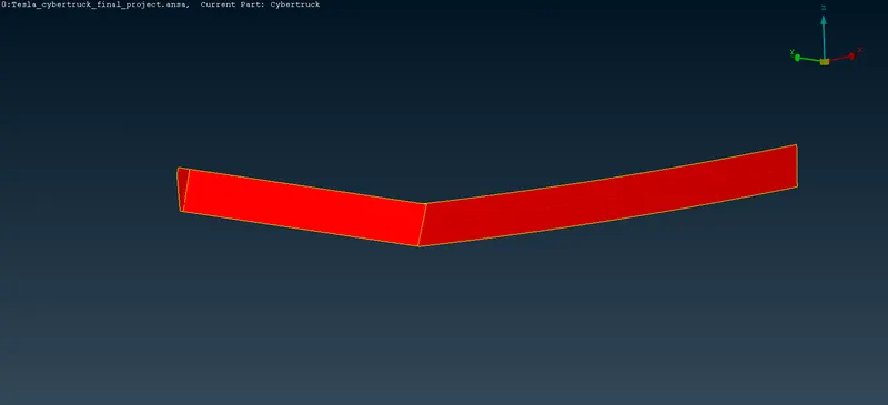

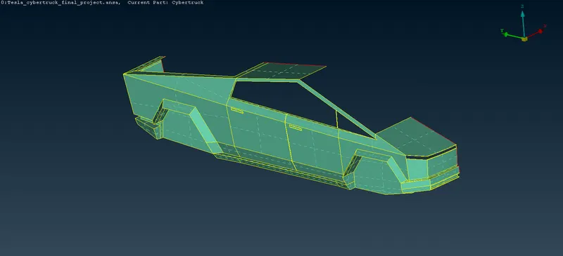
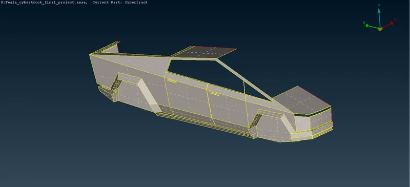
After assigning the PIDs we can able to see the Unwanted PIDs present can be deleted by Compress Tool.
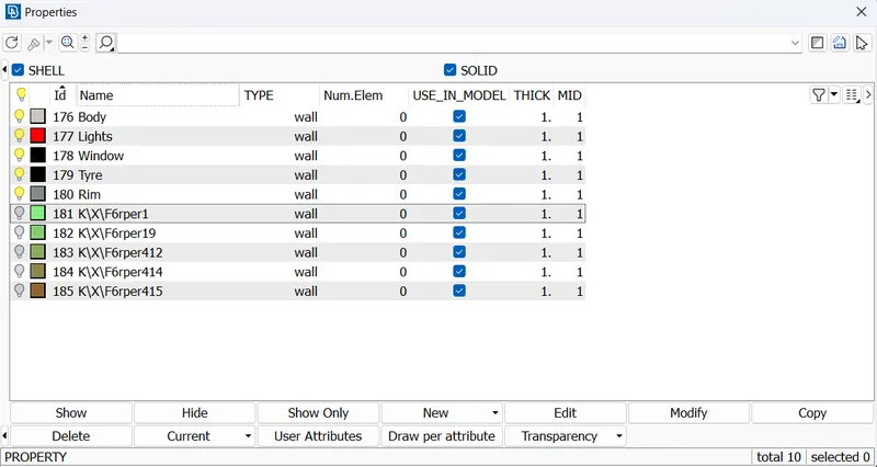
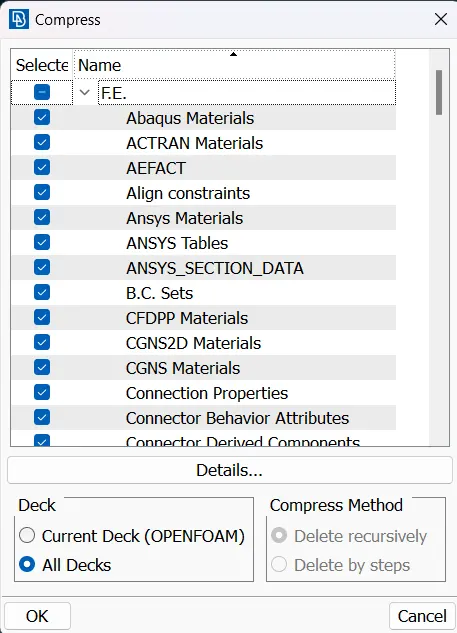
- FINAL RESULTS.
- MESHING.
A Mesh is a network that is formed of cells and points. It can have almost any shape in any size and is used to solve the PDEs (Partial Differential Equation). Each cell of the mesh represent an individual solution of equation which, when combined for the whole network, results in a solution for entire mesh.
SURFACE MESH.
A surface Mesh is a representation of each individual Surface Constituting the Volume mesh. It consists of FACES and VERTICES. Depending on the Pre-processing Software, feature Curves also included. Generally, a Surface Mesh should not have Free edges, and the edges should not be shared by two triangles.
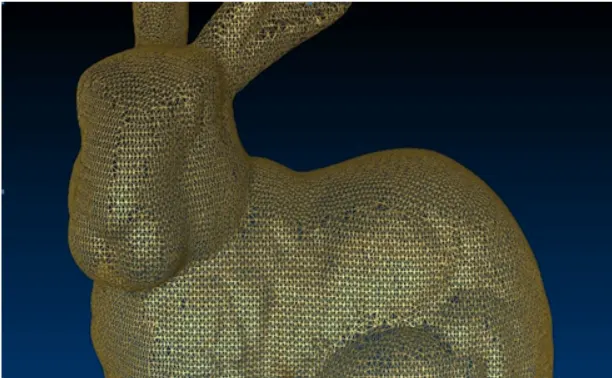
The Surfaces should contain the following qualities of triangles faces.
- Equilateral Sized Triangles
- No Sharp angles with the triangle Sphere
- Gradual Variation in triangle Size from one to the next.
- Surface Mesh generation process should be considered carefully. It has the Direct influence on the quality of the resulting Volume mesh and the effort it takes to get to this step.
SOLID MESH.
Solid Mesh, also known as volume mesh, is a polygonal Mesh representation of the interior Volume Of an Object. There are different types of meshing models that can be used to generate a volume mesh from a well prepared surface mesh.
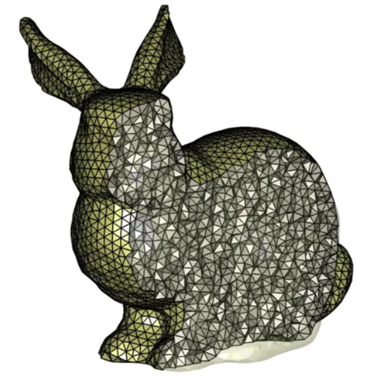
Three Types of Meshing models are follows,
- TETRAHEDRAL - Tetrahedral cell shape based core mesh.
- POLYHEDRAL - Polyhedral cell shape based core mesh.
- TRIMMED - Trimmed hexahedarl cell shape core mesh.
Once the volume mesh has been built, It can be checked for errors and exported to the other packages if desired.
SIGNIFICANCE OF MESH.
- The mesh influences the Accuracy, Convergence, and Speed of the Simulation.
- In this Process, the continuous geometric space of an objectis broken down into thousands or more of elements to properly define the physical shape of the Object.
- A Good quality Mesh gives more precise results, whereelse a poor Mesh can results in Convergence difficulties, which leads to incorrect results and flase conclusion.
- TYRE/RIMS.
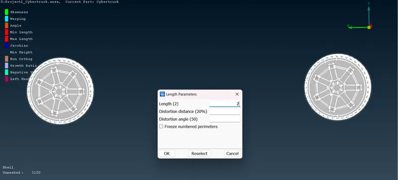
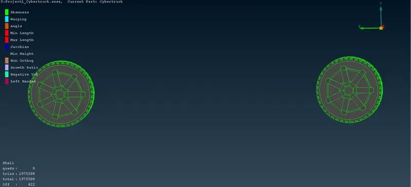
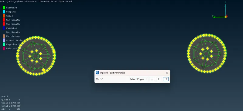
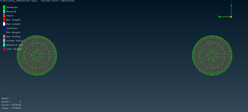
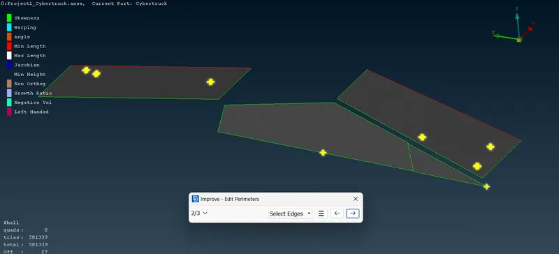
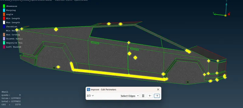
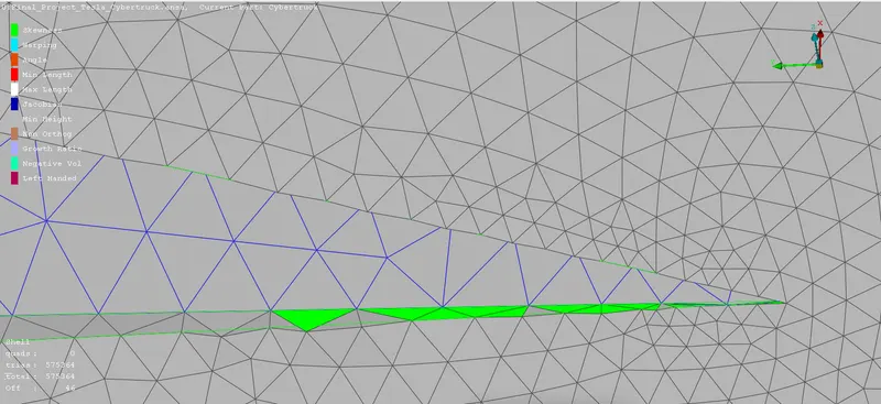
Now Start Meshing the Tesla Cyber-Truck Model One by One. Lets Start From the Tyres, Rims, Window, Lights and Finally Body. So lets isolate the Each Component by ENT/PID mode and lets give the required Quality Criteria. In Quality Criteria we need to Select the SKEWNESS, MIN-LENGTH, MAX-LENGTH, MIN-ANGLE-TRIAS, MAX-ANGLE-TRIAS. Quality must be in the FLUENT OPTION. When We start Processing the MESH we need to change SHADOW MODEL to the HIDDEN MODE, Because in Hidden Mode we can able to see the OFF ELEMENTS present need to Clear those OFF ELEMENTs. The OFF ELEMENTS can be removed by RECONSTRUCT Option. Sometimes after doing the Reconstruct there may be Still OFF ELEMENTs will be present. we can go check in the TOPO mode and can Use the CUT Option in that area. In Small regions OFF ELEMENTS can't be removed in that case we can Use MOVE option to the remove the OFF ELEMENTs, (SPILT Tools also used). Our task is to bring the OFF ELEMENTS into ZERO.
| Target Length | 2mm |
| Mininum Length | 0.5mm |
| Maximum Length | 5mm |
| Element Type | Trias |
| No of Elements | 1975588 |
| Off Elements | 422 |
| Off Elements Cleared | Yes |
| Total No Of Elements | 1978060 |
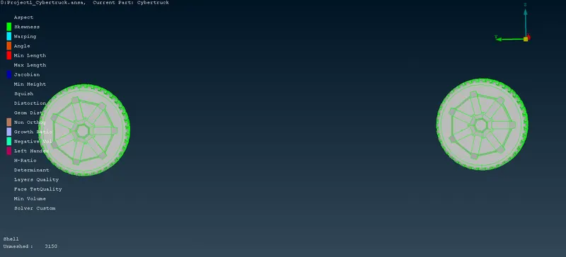
- FINAL OUTPUT.
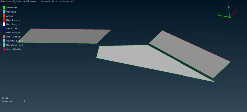
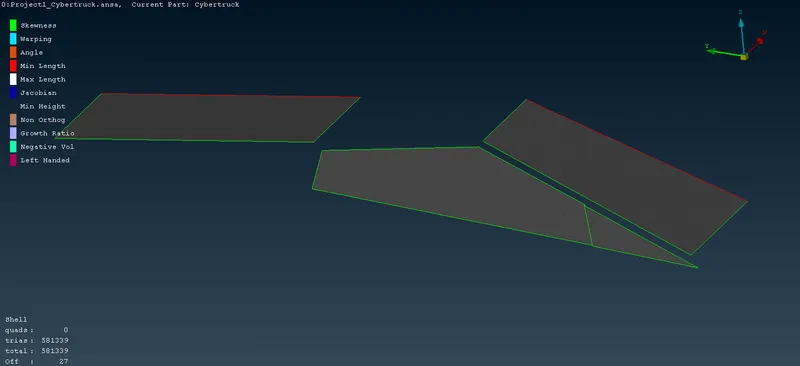
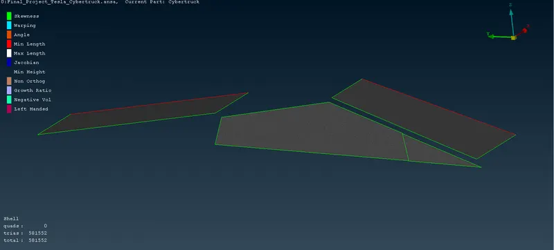
- WINDOWS.
| Target Length | 2mm |
| Mininum Length | 0.5mm |
| Maximum Length | 5mm |
| Element Type | Trias |
| No of Elements | 581339 |
| Off Elements | 27 |
| Off Elements Cleared | Yes |
| Total No Of Elements | 581552 |
- RECONSTRUCT.
- FINAL OUTPUT.
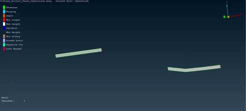
- LIGHTS.
| Target Length | 4mm |
| Mininum Length | 1mm |
| Maximum Length | 6mm |
| Element Type | Trias |
| No of Elements | 10435 |
| Off Elements | - |
| Off Elements Cleared | Yes |
| Total No Of Elements | 10435 |
- FINAL OUTPUT.
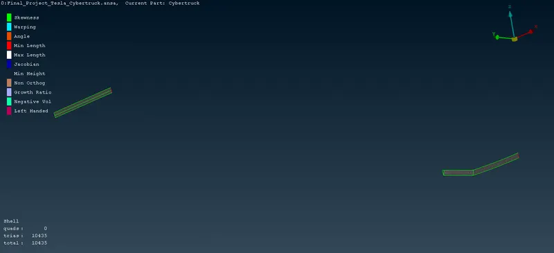
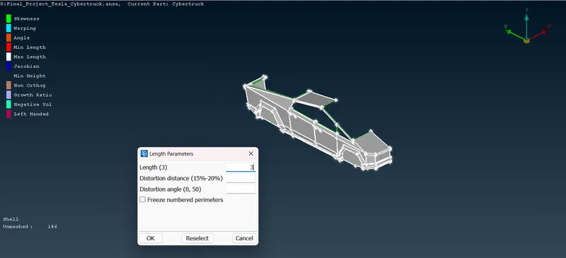
FREEZE OPTION is used, So that we can freeze the Meshed Surfaces, in Such a way mesh can not be collide to the other Surfaces or getting Erased.
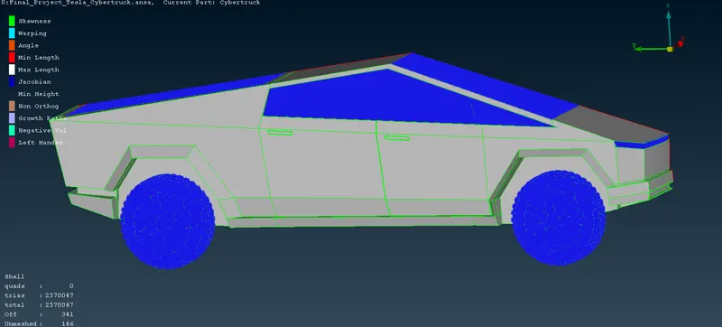
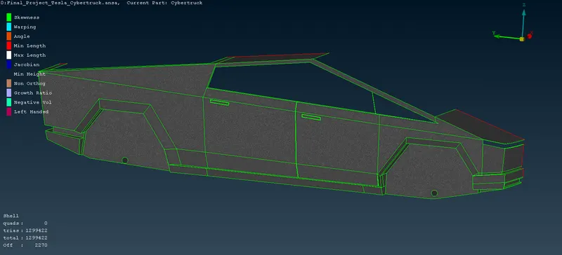
- BODY.
| Target Length | 3mm |
| Mininum Length | 0.5mm |
| Maximum Length | 5mm |
| Element Type | Trias |
| No of Elements | 1299422 |
| Off Elements | 2270 |
| Off Elements Cleared | Yes |
| Total No Of Elements | 2517566 |
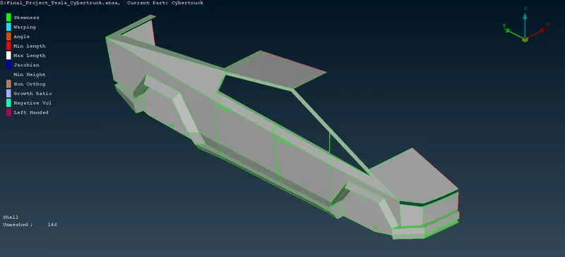
- SKEWNESS.
- FINAL OUTPUT.
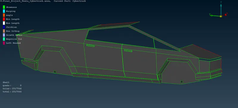
- ZERO OFF-ELEMENTS_FINAL_RESULTS.
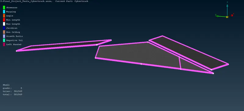
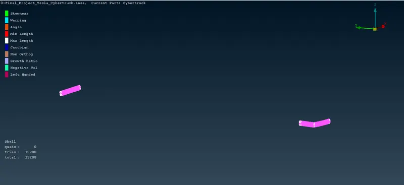
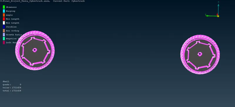
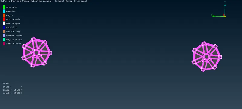
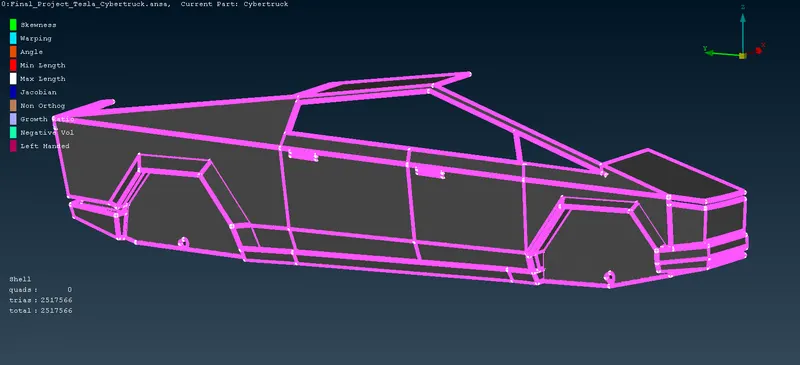
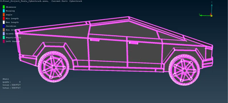
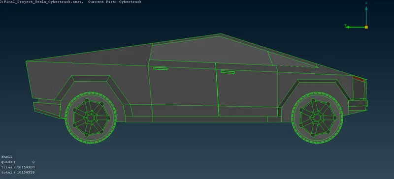
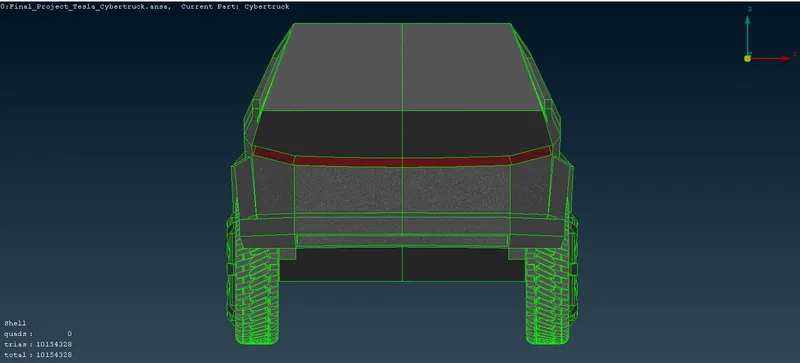
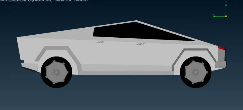
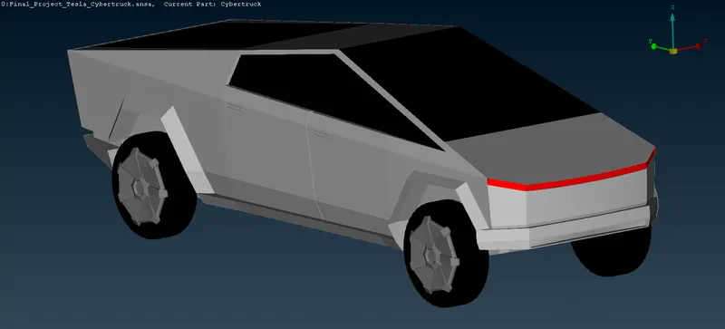
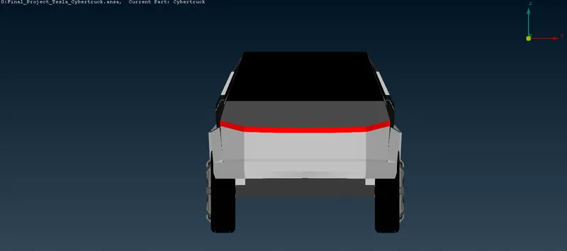
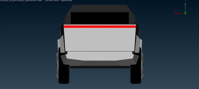
After Completing the Meshing with Zero Off-Elements, Now Next Step is to replicate the other Half Portion Of Car with the help of TRANSFORM Command.
TRANSFORM `rarr` COPY(Entities) `rarr` 3-POINT MIRROR.
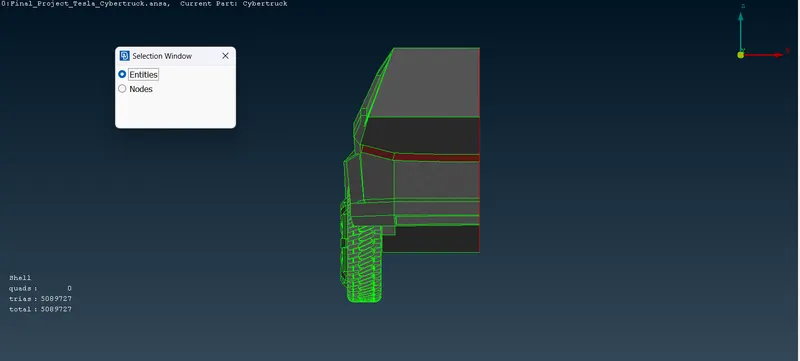
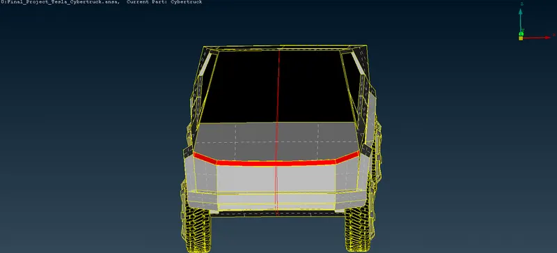
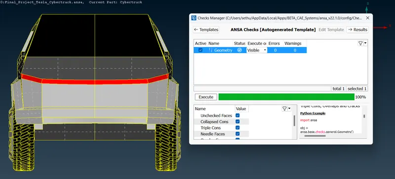
SINGLE CONS, with the PASTE Tool it can be Solved.
- GEOMETRY CHECK.
- WIND TUNNEL.
SIMULATION Can be Done by Two Methods - INTERNAL/EXTERNAL FLOW.
In Our Project Tesla Cyber-Truck external flow simualtion is done. To perform the CFD Flow analysis Wind Tunnel is created around the Car. It can be Created in TOPO mode itself.
DIMENSIONS.
Height Of the Car - 1540 mm
Total length Of the Car - 5773 mm.
To Create the Wind Tunnel Dimensions are Important, as for Front area 4x, Rear End Area 6x, and Top Surface area is 3x. In the POINTS Tools there is an RELATIVE Option click the Relative Option Select the Nodes bottom of the Center Of the Car and give a distance around 500mm. For Frontal area 4*5773 = 23092 + From the Center the car 2772 total 25864. For Top Surface 3*5773 = 17319 + height of the car(1540) = 18859. same for the Rear side needed to done. After Completing in the CURVES TOOLS Create Option is used to create the Lines. Then with the help of New Coons Options Surfaces are Created.
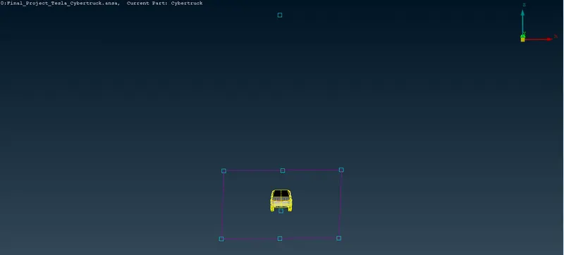
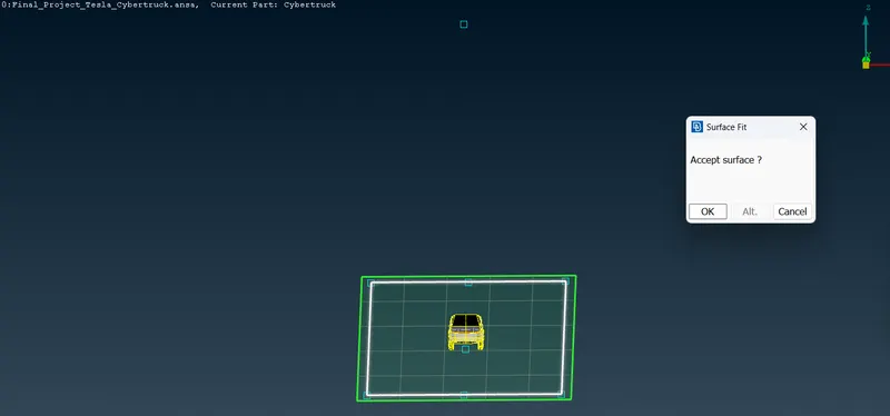
OFFSET Command is Used to create the Top Surfaces. (-18859)
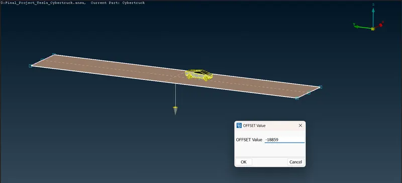
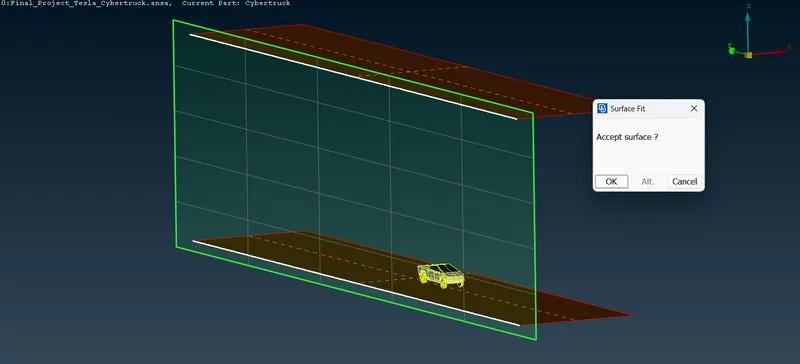
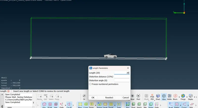
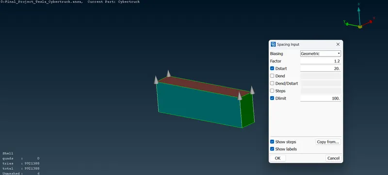
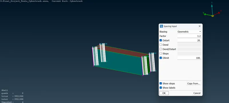
After making the Surfaces for all the Sides which include ( BASE, TOP, SIDE, FRONT, REAR Surfaces) now we need to create and assign the PIDs for those Surfaces. Then we need to mesh those Surfaces For Base Surface Tunnel - 20 mm; Top Surface Tunnel - 100 mm and for Side Surface Tunnel we can use the Spacing Option
Spacing `rarr`Growth Factor - 1.2; (d-minimum value) - 20 mm; (d-maximium Value - 100 mm ).
When we finished assigning the Quality Criteria, Now we can generate the Surface mesh for the Wind Tunnel.
- FINAL OUTPUT.
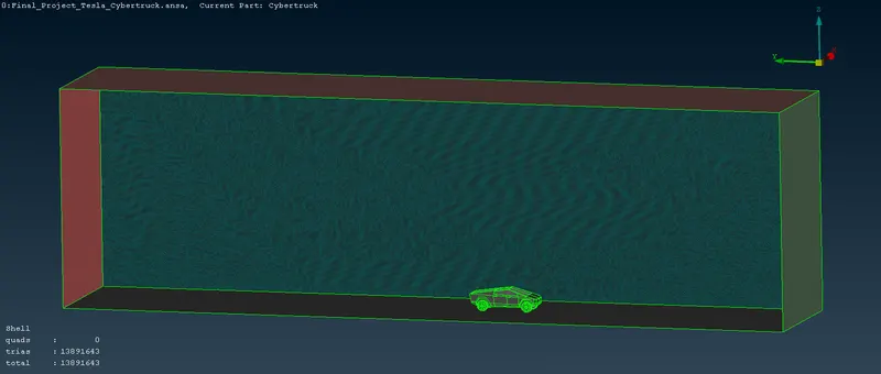
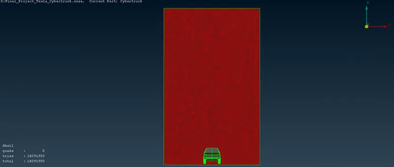
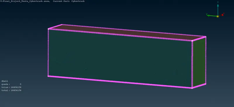
After Surface Meshing is Completed, now Volumetric mesh is needed to be done. we need to define the Volumes. Volumetic Mesh(tetra Elements) takes 2-3 days of meshing Process. So we can finish here itself.
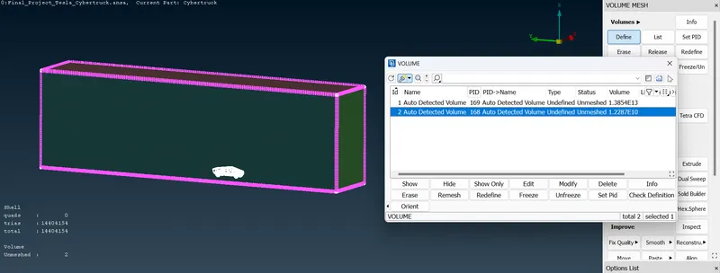
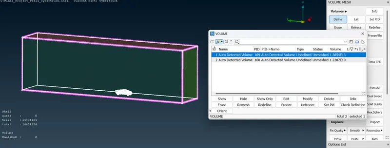
CONCLUSION.
- Hence we can come to conclude that CFD meshing for Tesla Cybertruck model which has the Geometric errors like Single Cons, Missing Surfaces, Unwanted Surfaces are rectified and hence the results are satisfied.
- Surface Mesh is generated for both the CAD Model and Wind Tunnel with required Target Length respectively.
https://drive.google.com/file/d/1dnnH7tKXk6h5JiXskOJRAq5Pl5vZD8nS/view?usp=sharing