Week 2 - Flow over a Cylinder.
AIM:-
- To Simulate the Flow Over a Cylinder Using Ansys Fluent.
OBJECTIVES:-
- To Simulate the Flow with Steady and Unsteady case and calculate the Strouhal number for Re = 100.
- To calculate the co-efficient of drag and lift over a cylinder by setting the Re number to 10,100,1000,10000,10000 (Run With Steady Solver).
- Discuss the effect of the Re number on co-efficient of drag (Results should be validated with any standard literature and error should be within 5%).
KARMAN VORTEX STREET.
STROUHAL NUMBER.
CO-EFFICIENT OF DRAG AND LIFT.
REYNOLDS NUMBER.
STEADY STATE /TRANSIENT STATE.
SOURCE-(WIKIPEDIA).
- FLOW OVER A CYLINDER.
INTRODUCTION.
- Flow Over a Cylinder is important in many Industrial Application like cooling of iron or cylinder pipe.Circular pipes have more applications in Heat Exchanger.High temperature flue gases flow over a circular cylinder in a cross flow. Depending on the flow rate, fluid properties and size of the cylinder, the flow can be laminar, transition and turbulent.
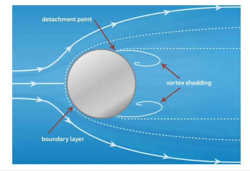
KARMAN VORTEX STREET. ( THEODORE VON KARMAN)
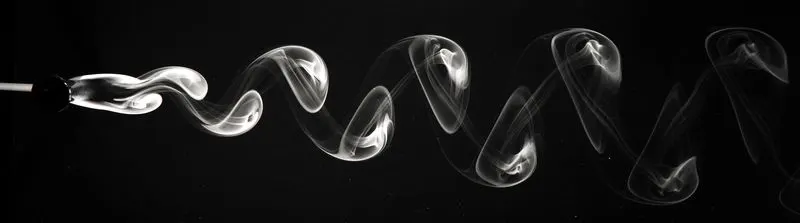
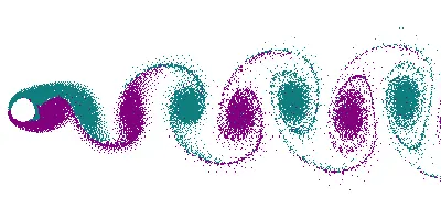
- In Fluid dynamics, a Karman Vortex (or a non Karman Vortex Street) is repeating pattern of swirling Vortices, caused by a process known as Vortex Shedding, Which is responsible for Unsteady Sepration of flow of a fluid around blunt bodies.
- For Common Flows (incompressible or isothermal), the Kinematic viscosity is everywhere uniform over all the flow field and constant in time, so there is no choice on the viscosity paramter, which becomes naturally the kinematic viscoisty of the fluid being considered at the temperature being considered.On the Other hand, the reference length is always an arbitrary parameter, so particular attention should be put wwhen comparing flows around different obstacles or in channels of different shapes.The gobal reference number should be considered as the same length.This is actually the reason for which the most precise sources for airfoil and channel flow data specify the reference length at the reynold's number.The reference length can vary depending on the analysis to be performed,for a body with circle sections such as circular cylinder or a bluff body or a revolution body like a fuselage or a submarine, it is usually the profile chord or the profile thickness, or some other given widths that are in fact stable design inputs, for flow channels usually the hydraulic diameter about which the fluid is flowing.
ANIMATION OF KARMAN VORTEX STREET.
- For aerodynamic profile the reference length depends on the analysis. In fact, the profile chord is usually chosen as the reference length also for aerodynamics coefficient for wing sections and thin profiles in which the primary target is to maximize the lift co-efficient or the lift/drag ratio ( that is as usual in thin airfoil theory, one would employ the chord Reynolds as the flow speed parameter for comparing different profiles).
- The range of Reynold's Values varies with the size and shape of the body from which the eddies are shed, as well as with the kinematic Viscosity of the fluid. For the wake of a circular cylinder, for which the reference length is conventionally the diameter d of the circular cylinder, the lower limit of this range is `Re approx 47`.
STROUHAL NUMBER.
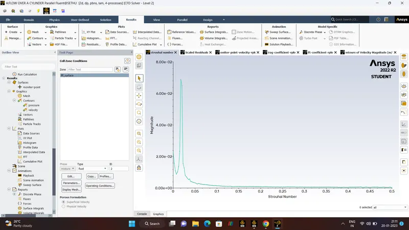
- Strouhal Number is dimensionless number describing Oscillating Flow Mechanism. Strouhal Number is given by,
`St = (f*L)/(v)`
Where,
f - Frequency of Vortex Shedding.
L - Characteristic length.
v - Flow Velocity.
DRAG CO_EFFICIENT.
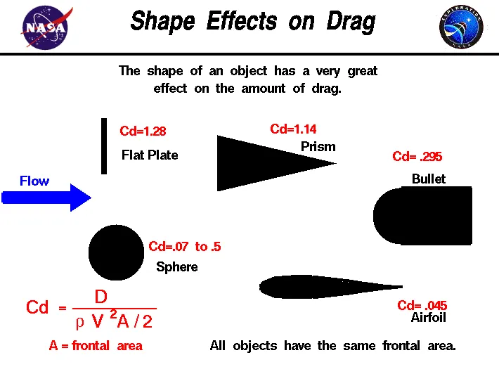
- Drag Co-efficient is a dimensionless quantity that is used to determine the Drag or Resistance of an Object in a Fluid Envirnoment, Such as Air or Water. The Drag Co-efficient is given as
`C_d = F_d /(1/2*rho*a *v^2)`
Where,
`C_d` - Co-efficient Of Drag.
`F_d` - Drag Force.
`rho` - Density.
`a` - Area with respect to which Drag Force is Calculated.
`v^2`- Flow Velocity.
LIFT CO_EFFICIENT.
- Lift Co-efficient is a dimensionless quantity that is used to determine the Lift of an Object in a Fluid Envirnoment. The Lift Co_efficient is given by
`C_l = F_l /(1/2*rho*a *v^2)`
Where,
`C_l` - Co-efficient Of Lift.
`F_l` - Lift Force.
`rho` - Density.
`a` - Area with respect to which Lift Force is Calculated.
`v^2`- Flow Velocity.
REYNOLD'S NUMBER.
HISTORY – (Osborne Reynolds in 19th century)
- The Reynold's Number is Dimensionless number, named after the Osbrone Reynolds, defined as the ratio of Interia Forces to Viscous Forces. That is Reynold's Number is given by
`Re = (rho*v*D)/(mu)`
Where,
`D`- Diameter (m).
`v` - Velocity Of Fluid (m/s).
`mu`- Kinematic Viscosity of Fluid `m^2/s``
`rho - Density`
SIGNIFICANCE.
- Re is Used in Forced Convection.
- Forced Convection is a Type of Heat Transfer, in which Fluids are forced to move, In Order to Increase the Heat Transfer.
- Re number is Used to predict the Flow patterns in different fluid situations.
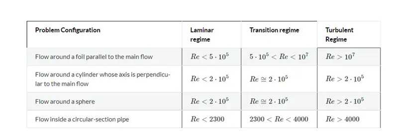
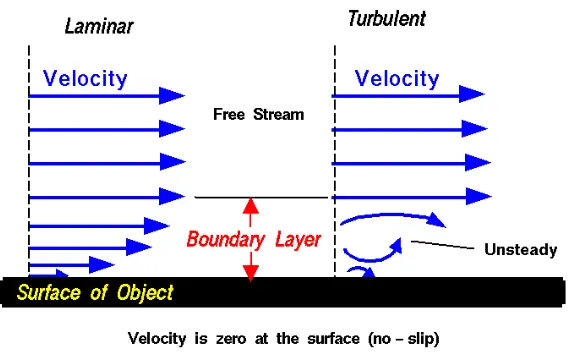
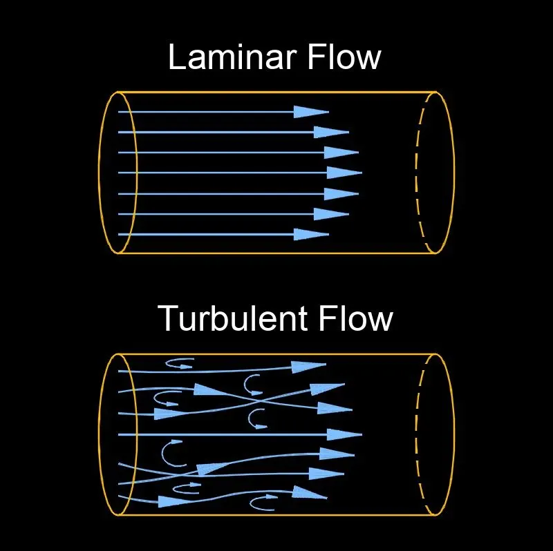
- At Low Reynold's Number the Flow tends to be Laminar Flow.
- At High Reynold's Number the Flow tends to be Turbulent Flow.
-
Re<2000 (LAMINAR).
2000 < Re (TRANSITION).
Re>4000 (TURBULENT).
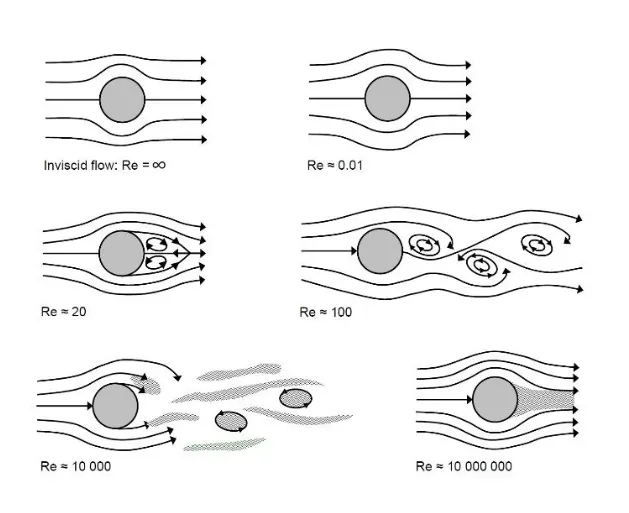
Larger vortex are found at lower Reynold's number.
- FLOW OVER A CYLINDER GEOMETRY.
STEP:- 1
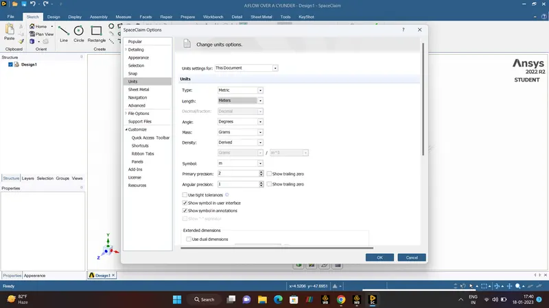
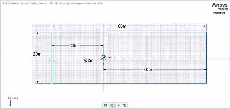
- For FLOW OVER A CYLINDER need to Create a geomerty, So open the anys fluent name it as flow over cylinder then Open the SPACECLAIM make UNITS as METERS then go to design Tool draw the geometry with respect to given dimension. The flowing dimesnions are,
- CIRCULAR CYLINDER (Diameter) = 2m.
- SYMMETRY WALL = 60m.
- Center of the cylinder towards left side is 20 distance and right side is 40 respectively.
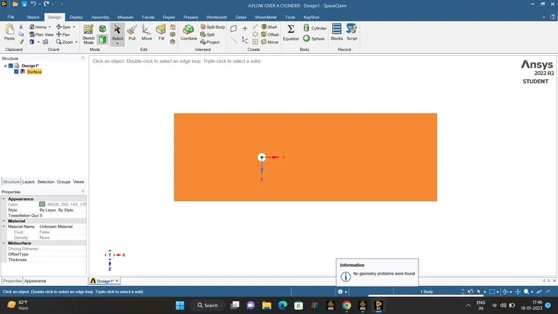
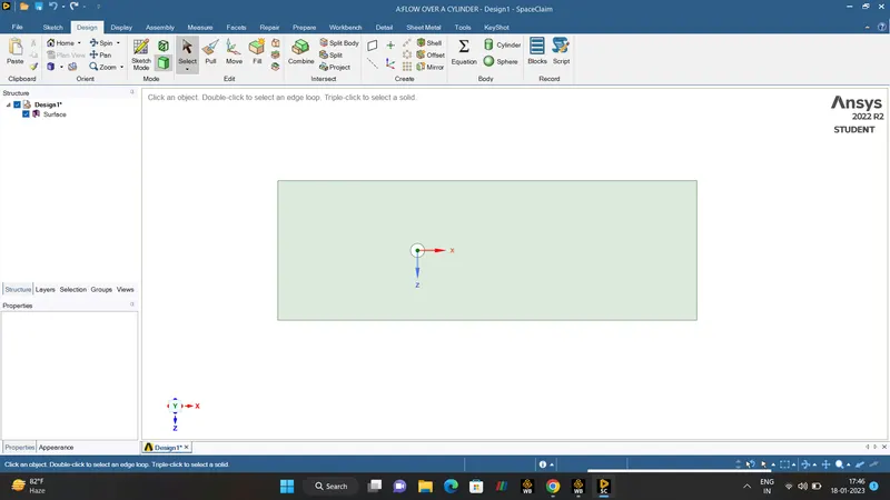
- With the help of the PULL tool select the geometry and delete the circle, then finally update the geometry.
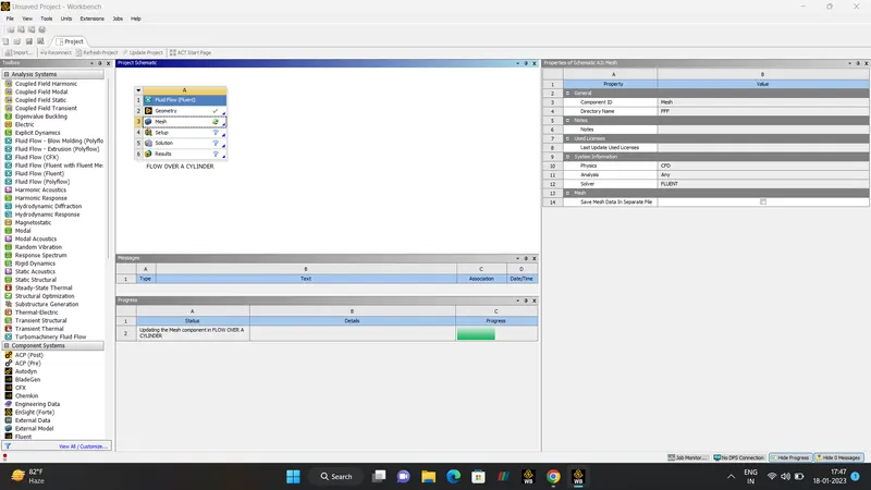
- SETUP:-
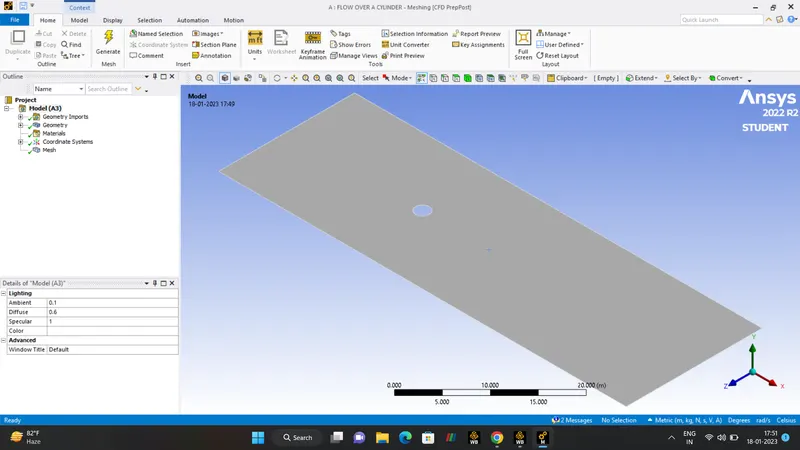
MESHING.
- Meshing is the major part of the engineering simulation process.Here are larger geometry is discretized into small simple elements in order to get the accurate solution.
- This mesh is a QUADRILATERAL mesh but for our problem we going to change into a triangular mesh.
- So, right click the MESH option in that just click the METHOD option and change into ALL TRIANGULAR METHOD.
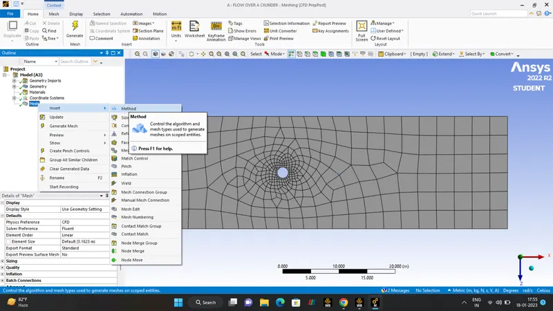
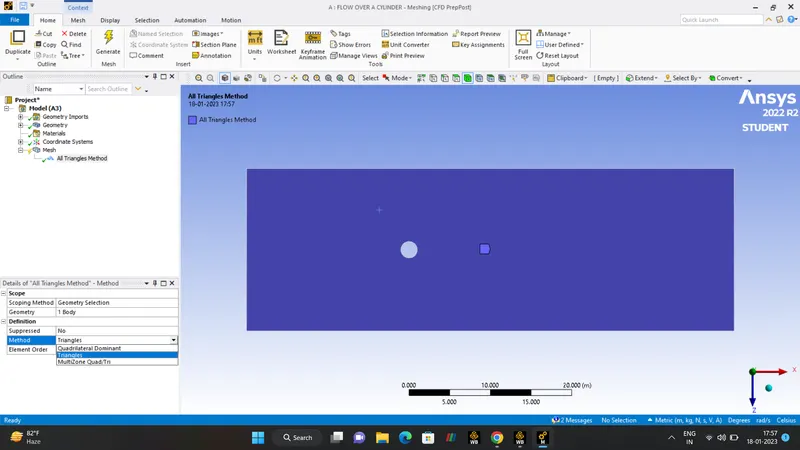
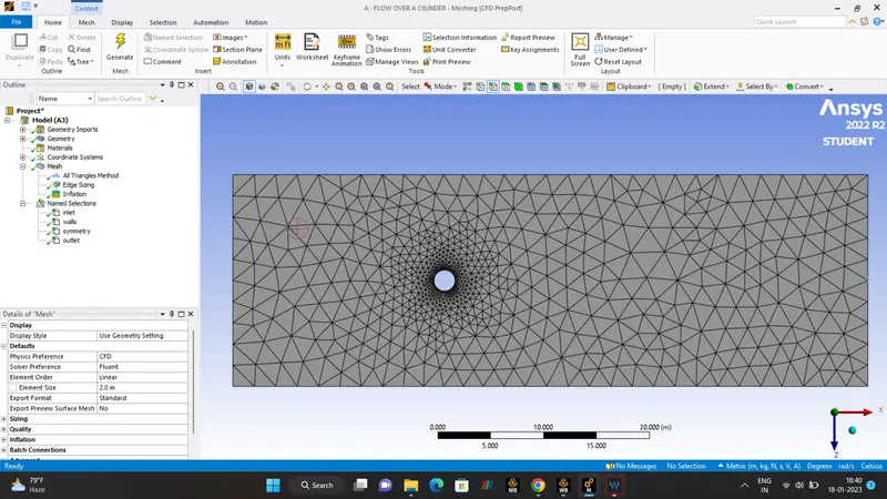
REGARDING MESHING WE NEED TO CHANGE THE ELEMENT SIZE INTO 0.25m. Hence the post-processing will be done.
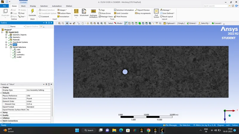 FINER MESH.
SIZING.
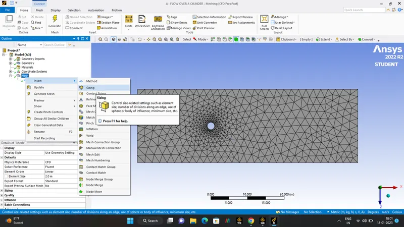
- There are various option of sizing is available,They are
- BODY
FACE
EDGE
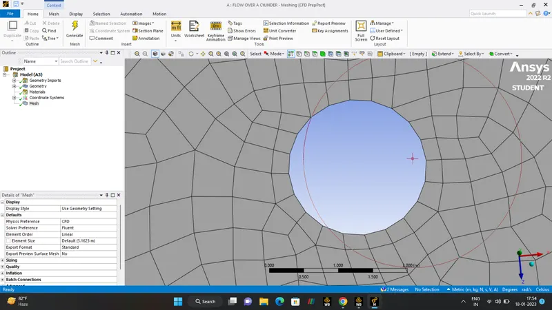
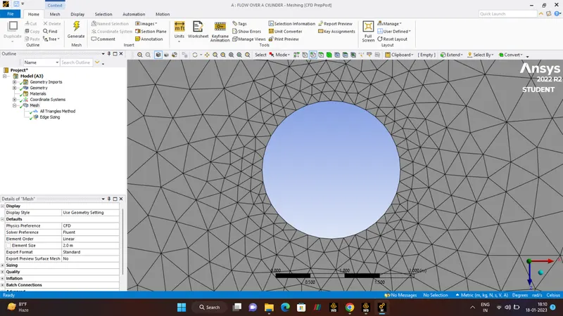
SPHERE OF INFLUNENCE. - In Our Case we need EDGE SIZING, because in below fig, it is clearly shown that Circular Cylinder isn't perfect.
- In Sizing we need to give number of division instead of element size. As per circle is consider has an 360 degree , every 10 degree is been calculated.
NUMBER OF DIVISION - 36.
Before SIZNIG is done and after image.
INFLATION.
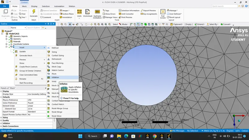
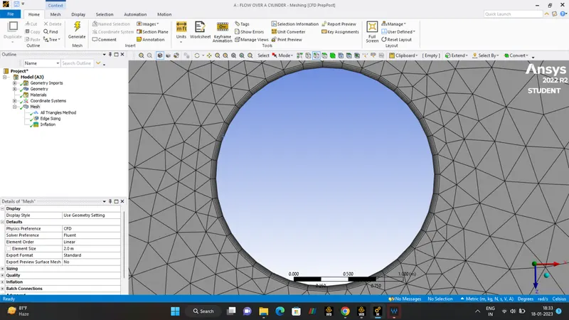
- Inflation Layers are fine layers of mesh around the domain.
- Just right click the mesh into the select option - inflation.
- There are two options regarding GEOMETRY and BOUNDARY.
- In GEOMETRY option there is BODY or FACE option to create the inflation.
- In BOUNDARY Option there is EDGE or FACE option to create the inflation.
- In our case we going to select the edge and face .
- FIRST LAYER THICKNESS and 6 LAYERS. AFfter creating the INFLATION then generate the MESH.
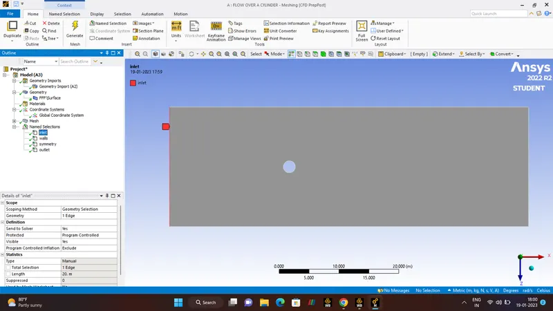
- Almost done the setup, Finally naming the geometry and checking.
- Select the EDGE and name it has INLET and OUTLET. and Face name it has SYMMETRYWALLS. then do checking for clarity purpose.
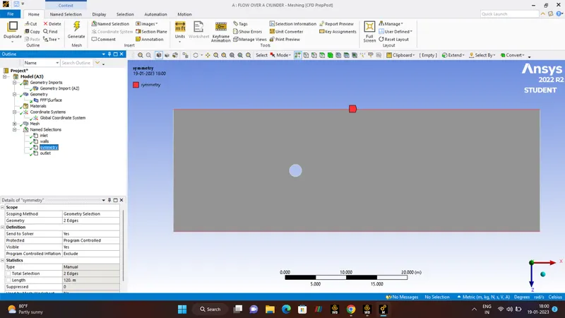
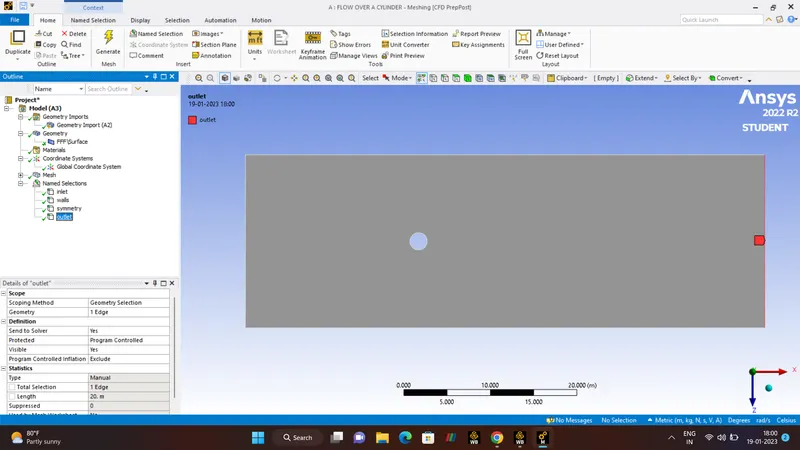
- SOLUTION:-
CHECKMESH.
- It evalutes the geometry for all factors responsible for the cell distortion and gives the evalution result whether the simulation is converged or not, whether the mesh is valid or not.
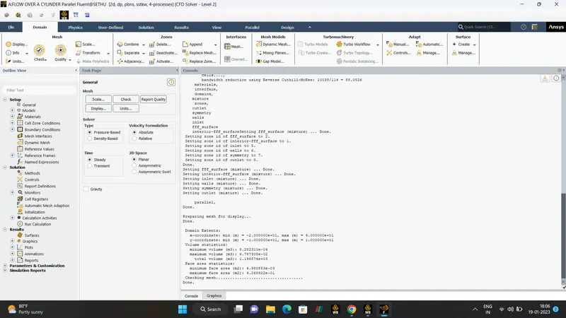
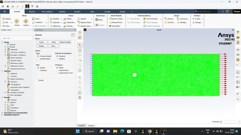
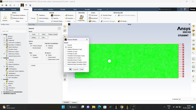
- In general setting up the physics in VISCOUS MODEL change into the LAMINAR FLOW Based on the REYNOLD"S NUMBER.
IN OUR PROBLEM ONLY LAMINAR FLOW IS USED.
LAMIINAR FLOW.
- Laminar flow occurs when the fluid flows in infinitesimal parallel layers with no disruption between them.
- In Laminar flow, the fluids layers slide in the parallel, with no eddies, swirls or current normal to the flow itself.
- This type of flow is also known as Streamline Flow because it is characterized by non-crossing stream line.
- The laminar regime, is ruled by Momentum Diffusion, while the momentum convection is less important. In more physical terms that viscous forces are higher than the inertial force.
- SETUP CONFIGURATION:-
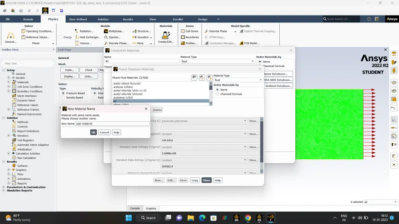
USER_MATERIAL.
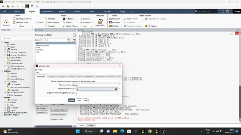
INLET-VELOCITY.
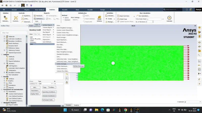
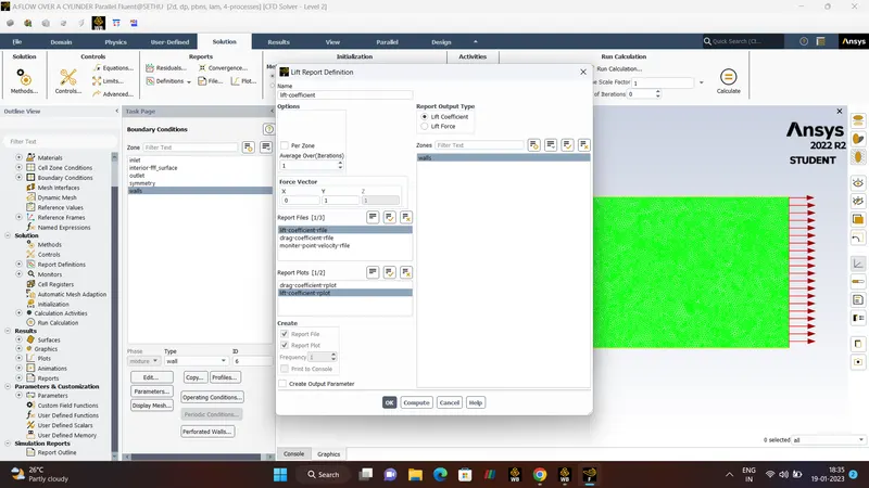
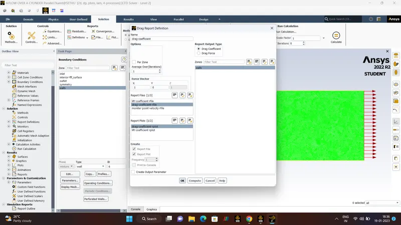
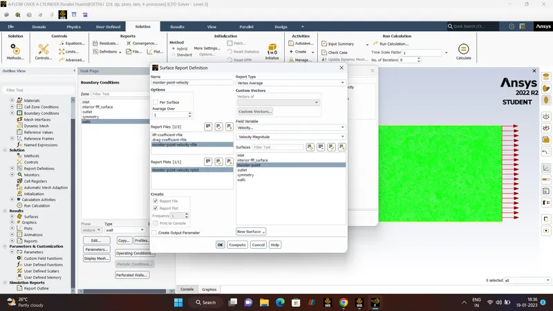
DEFINITON_NEW_VERTEX_AVERAGE/DRAG /LIFT - CO-EFFICIENT.
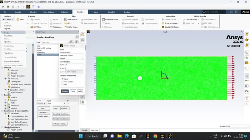
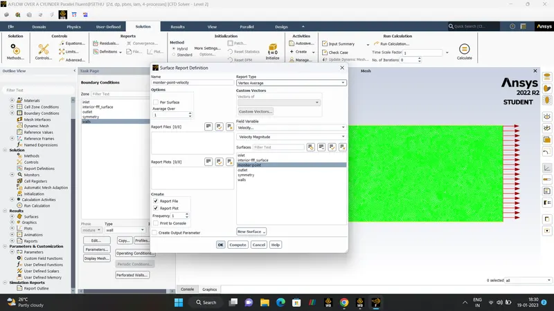
MONITOR-POINT-VELOCITY.
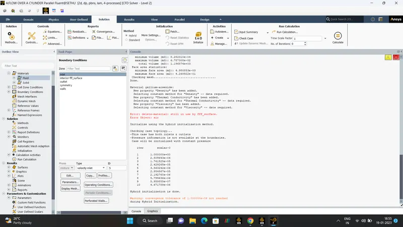
- Finally Hybrid Initializsation.(STEADY STATE).
VELOCITY/ PRESSURE CONTOUR. /ANIMATION VIDEO VELOCITY CONTOUR.
STROUHAL NUMBER.
VARIATION OF EFFECTS OF REYNOLD"S NUMBER WE ARE CHANGING THE KNIMEATIC VISCOSITY.
FORMULA.
`Re = (rho*v*D)/(mu)`
Where,
`D`- Diameter (m).
`v` - Velocity Of Fluid (m/s).
`mu`- Kinematic Viscosity of Fluid `m^2/s``
`rho - Density`
CASE:-1.
Re = 10.
v = 1.
D = 2.
rho = 1.
Effects of reynold's number
Kinematic Visocity ?
`Re = (rho*v*D)/(mu)`
`10 = (1*1*2)/mu`
`mu = 0.2`
Similarly for remaining REYNOLD"S NUMBER
CASE:-2
Re = 100 `mu = 0.02`
CASE:-3
Re = 1000 `mu = 0.002`
CASE:-4
Re = 10000 `mu = 0.0002`
CASE:-5
Re = 100000 `mu = 0.00002`
- POST-PROCESSING:-
PART-1 ( STEADY/ UNSTEADY STATE)
PLOT - STROUHAL NUMBER.
- STEADY STATE.
DEFINITION:-
- Steady State is defined as state of process which does not change with respect to time. Steady state will also change with respect to time but the changes will be very negligible.
- Steady state is independent of time.
- In Steady state method we can get the final solution at the last iteration and we can't get a solution inbetween.
- steady state will take less time to converge. It requires less space.
FOR, Reynold's Number 100. (Steady Simulation).
RESULTS.
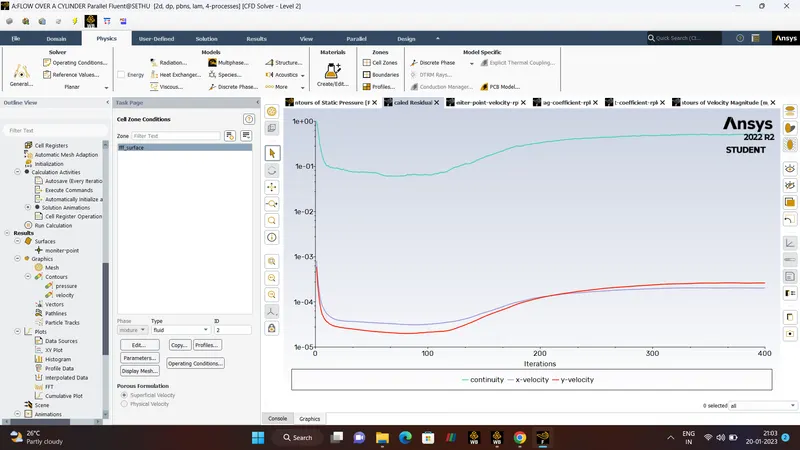
- RESIDUAL PLOT.
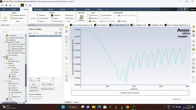
- MONITOR-POINT-VELOCITY.
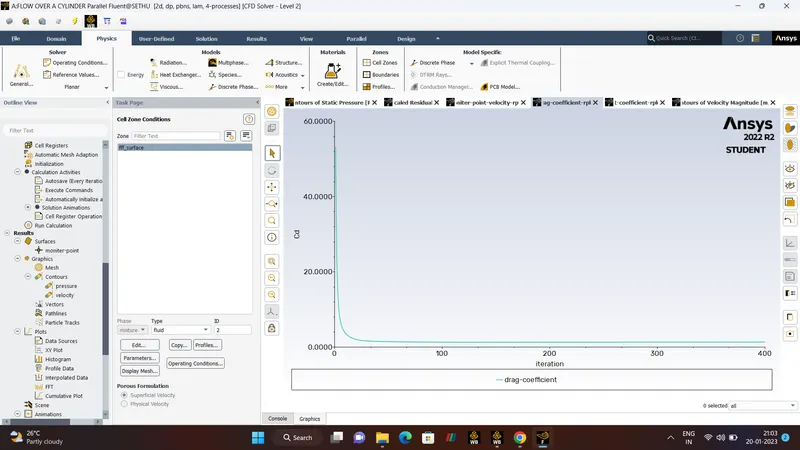
- DRAG COEFFICIENT.
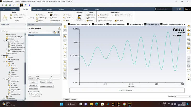
- LIFT COEEFICIENT.
- STROUHAL NUMBER.
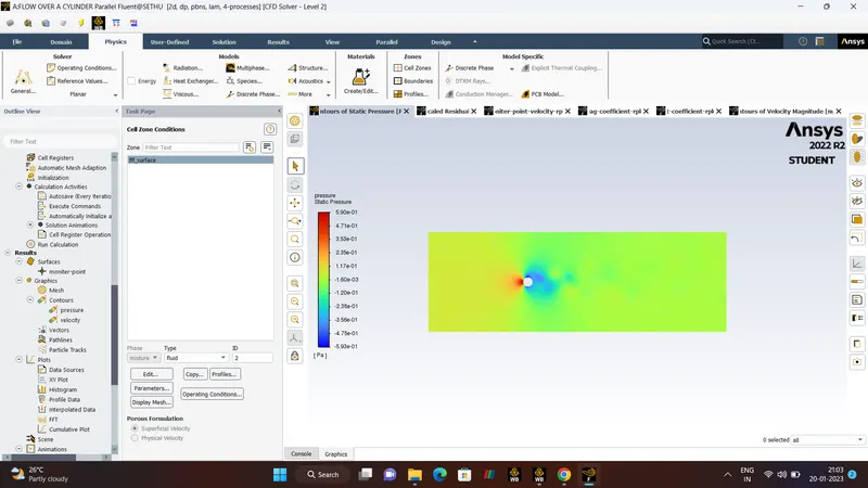
- PRESSURE CONTOUR.
- VELOCITY CONTOUR.
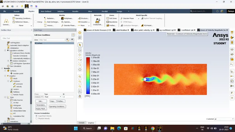
- ANIMATION OF VELOCITY CONTOUR.
- UNSTEADY/TRANSIENT SIMULATION.
DEFINITION.
- Transient state is defined as state of process which will change with respect to time and the properties of system will also change with respect to time.
- Transient state is dependent of time.
- In Transient state we get the itermediate solution in particular time step. The computational time will be more and requires more space.
REYNOLD'S NUMBER - 100 (TRANSIENT STATE).
- STANDARD INITIALIZATION.
TIME STEP - 350.
RESULTS.
- RESIDUAL PLOT.
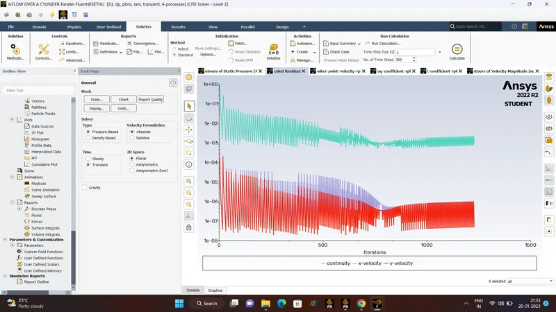
- MONITOR-POINT-VELOCITY.
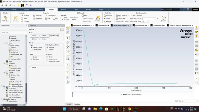
- DRAG COEFFICIENT.
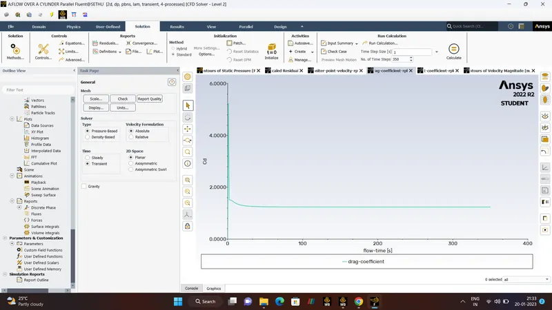
- LIFT COEFFICIENT.
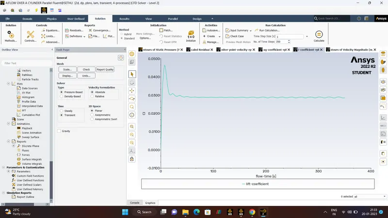
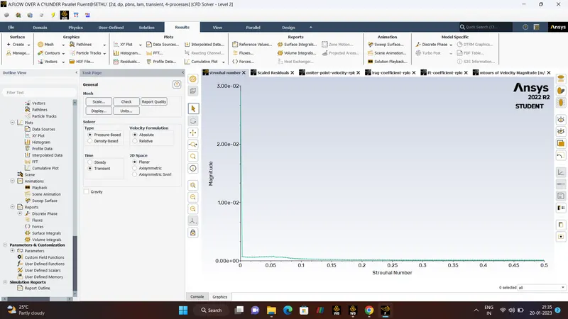
- STROUHAL NUMBER.
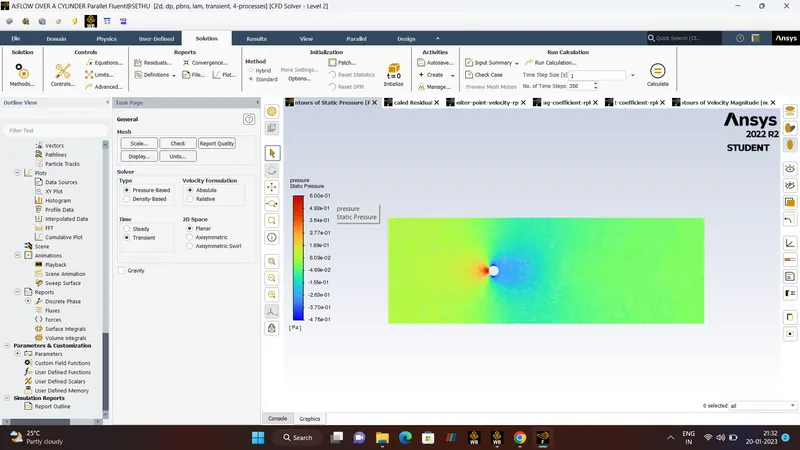
- PRESSURE CONTOUR.
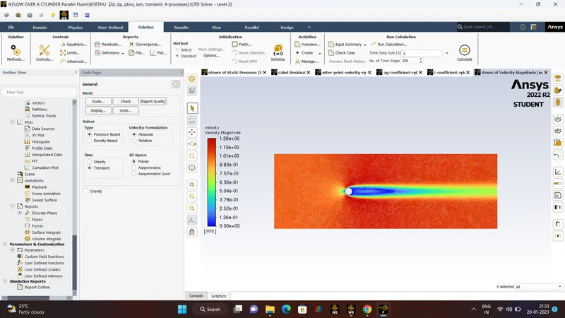
- VELOCITY CONTOUR.
- ANIMATION OF VELOCITY CONTOUR.
- PART-2 (STEADY STATE)
RE = 10
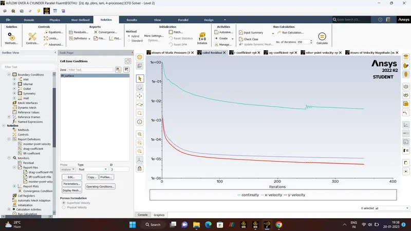
- RESIDUAL PLOT.
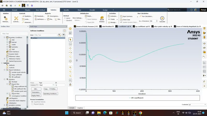
- LIFT-COEFFICIENT.
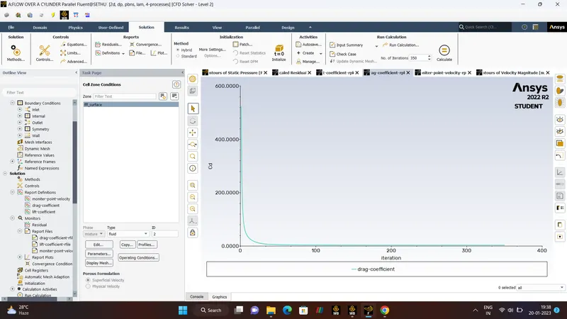
- DRAG CO-EFFICIENT.
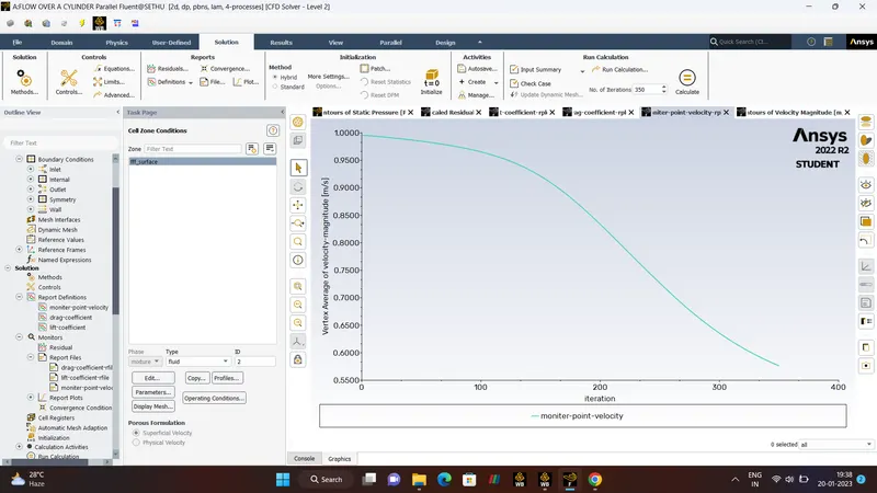
- MONITOR-POINT-VELOCITY.
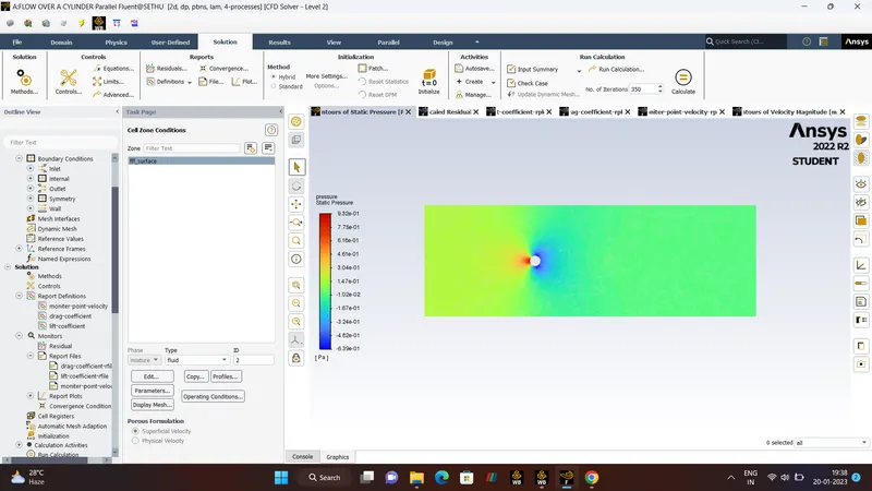
- PRESSURE-CONTOUR.
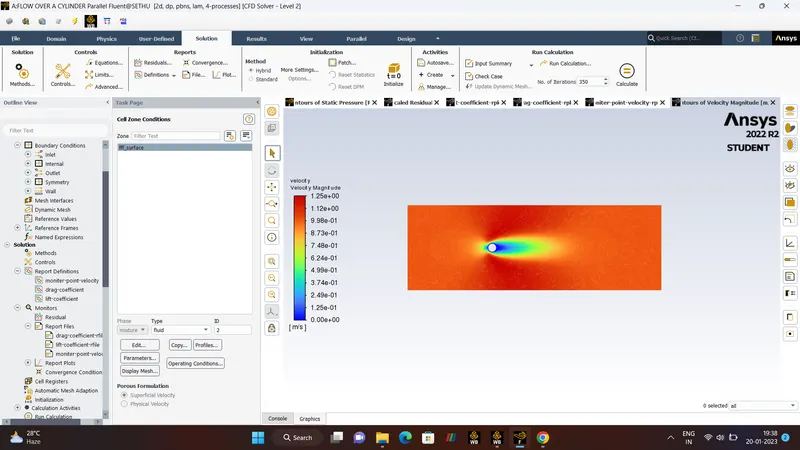
- VELCOITY-CONTOUR.
- ANIMATION OF VELOCITY CONTOUR.
- CASE - 2.
RE = 1000
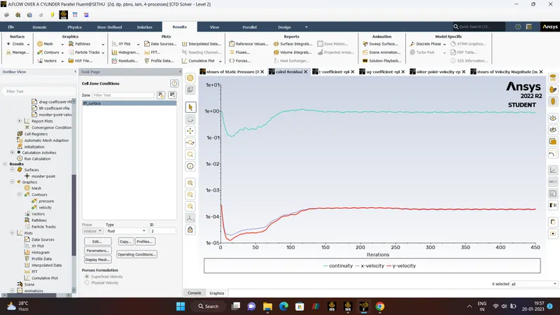
- RESIDUAL PLOT.
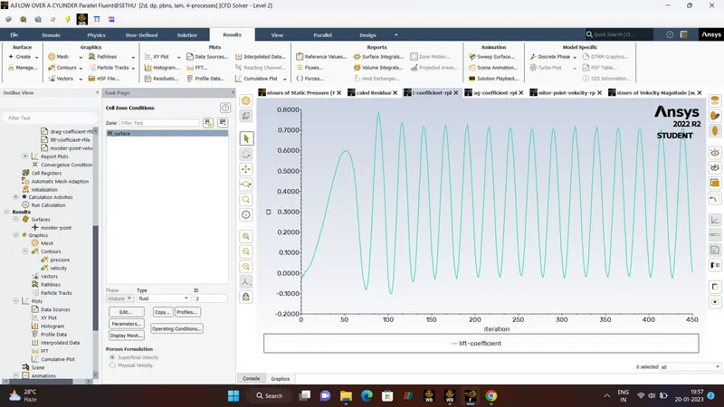
- LIFT-COEFFICIENT.
- DRAG CO-EFFICIENT.
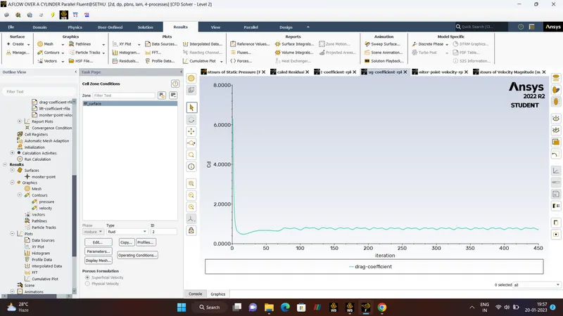
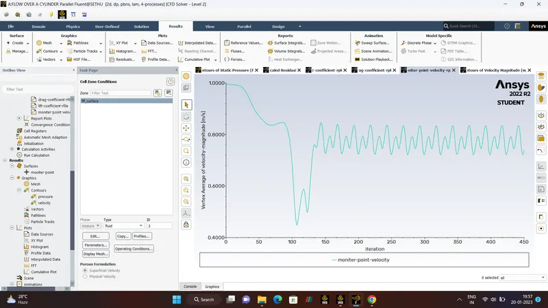
- MONITOR-POINT-VELOCITY.
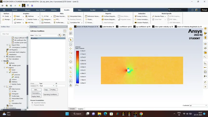
- PRESSURE CONTOUR.
- VELOCITY CONTOUR.
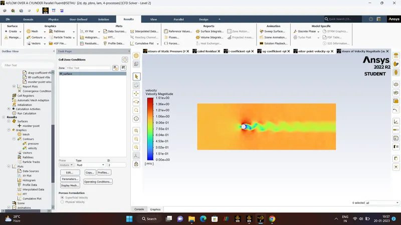
- ANIMATION OF VELOCITY CONTOUR.
- CASE - 3.
RE = 10000
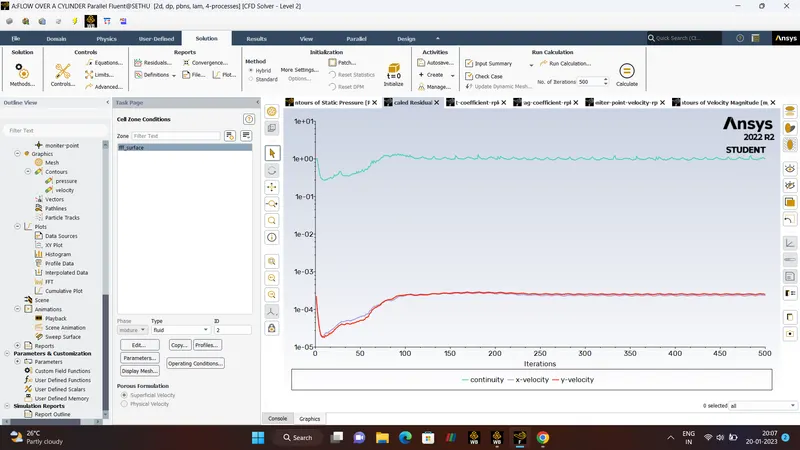
- RESIDUAL PLOT.
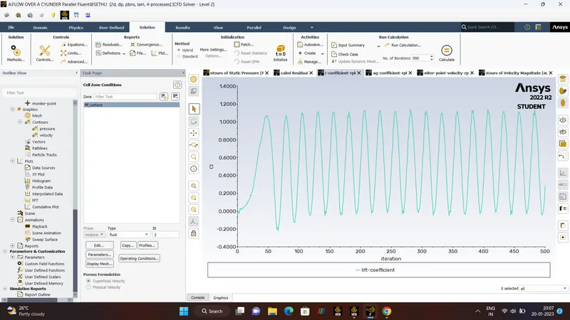
- LIFT-COEFFICIENT.
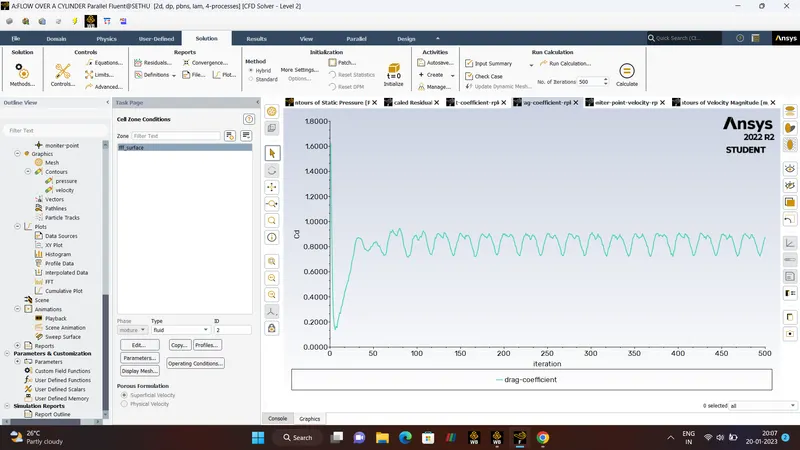
- DRAG CO-EEFICIENT.
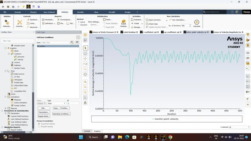
- MONITOR-VELOCITY-POINT.
- PRESSURE CONTOUR.
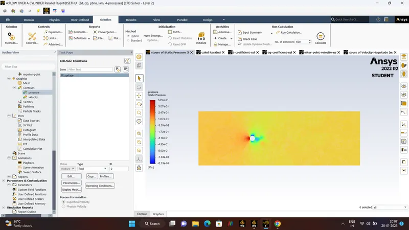
- VELOCITY CONTOUR.
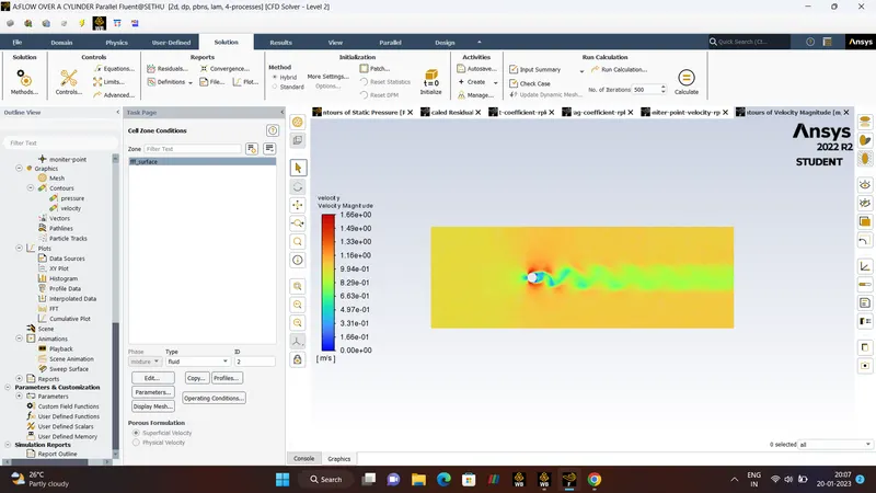
- ANIMATION OF VELOCITY CONTOUR.
- CASE- 4.
RE = 100000
- RESIDUAL PLOT.
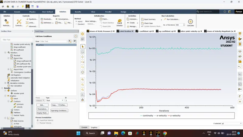
- LIFT COEFFICIENT.
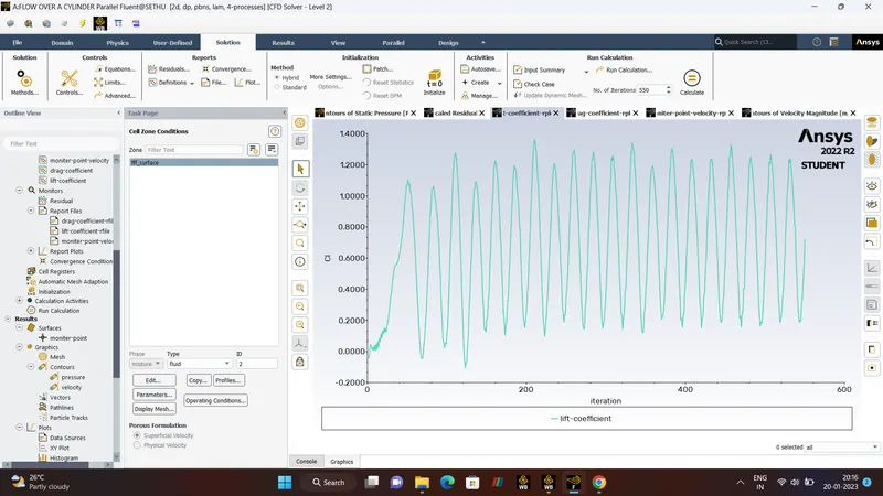
- DRAG COEFFICIENT.
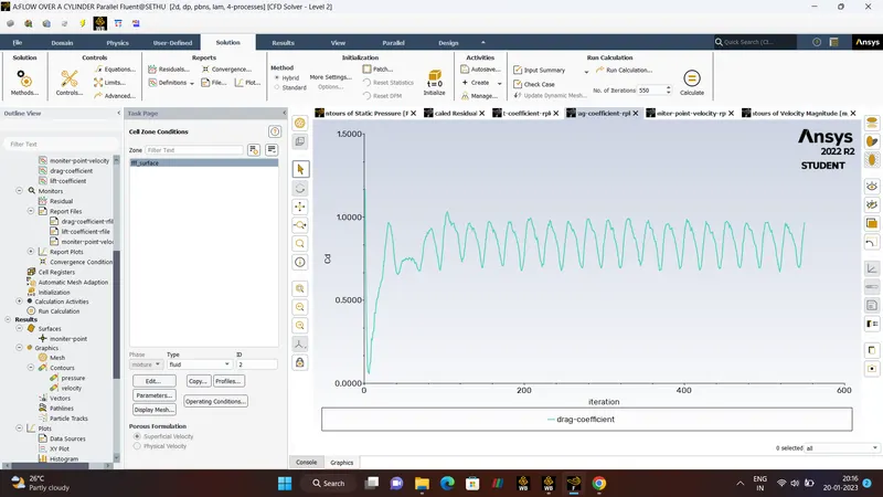
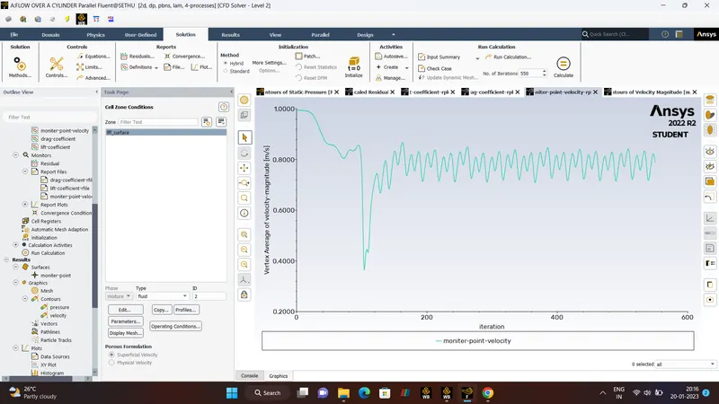
- MONITOR-VELOCITY-PLOT.
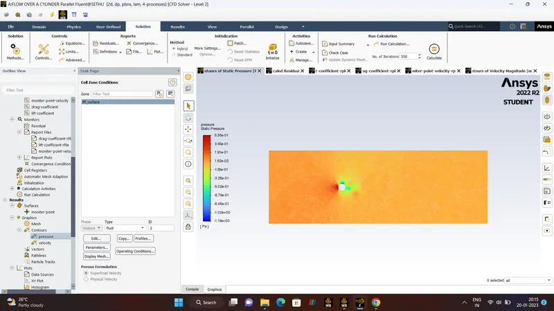
- PRESSURE CONTOUR.
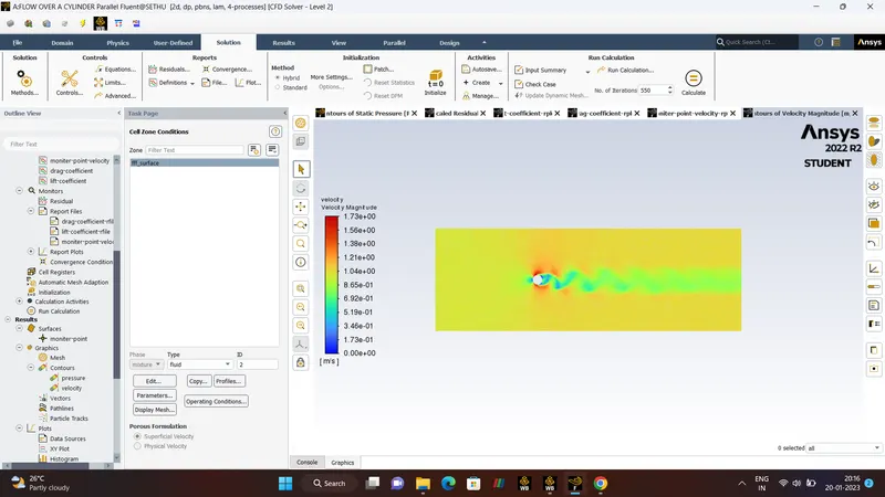
- VELOCITY CONTOUR.
- ANIMATION OF VELOCITY CONTOUR.
RESULTS:-
STEADT STATE. (LAMINAR FLOW)
| NO. | REYNOLD'SNUMBER (Re) | KINEMATIC VISCOSITY (`mu`) | NUMBER OF ITERATION | DRAG CO-EFFICIENT (Cd) | LIFT CO-EFFICIENT(Cl) |
| 1 | 10 | 0.2 | 350 | 3.34 | -0.003 |
| 2 | 100 | 0.02 | 400 | 1.33 | 0.174 |
| 3 | 1000 | 0.002 | 450 | 0.72 | 0.007 |
| 4 | 10000 | 0.0002 | 500 | 0.87 | 0.288 |
| 5 | 100000 | 0.00002 | 550 | 0.96 | 0.71 |
CONCLUSION:-
- Hence the Steady and UnSteady state Simulation for Reynold's number 100 and Strouhal number is calculated and the solution is converged.
- For Various Effects of Reynold's number that is ( 10,100,1000,10000,10000) is calculated and the Drag and Lift Coefficient is calculated,with the karman vortex street and the solution is converged.