Week -2
AIM :
- To make a Simulink model of a Doorbell using a Solenoid block .
- To use a thermistor to the sense the temperature of a heater and turn on or turn off the fan .
THEORY : DOORBELL .
- The first electric doorbell was invented in the year of 1831 by Joseph Henry .
WORKING PRINCIPLE :
- The most important part of a doorbell is its magnetic motor .
- The magnetic motor constitutes a conventional electromagnet .
- The electromagnet is an arrangement in which coil of wire wrapped around the magnetic material which produces the magnetic field when the electricity passed through the coil .
- The greater the coiling of wire , the higher the amplification of magnetic field .
- The magnetic filed produces a substantial on any magnetic substance when brought in the vicinity of it magnetic field.
- This means when an iron object is placed in its magnetic field , it will be attracted to the magnetic field due to the polar orientation generated by the electromagnetism .
ANIMATED GIF OF DOORBELL :
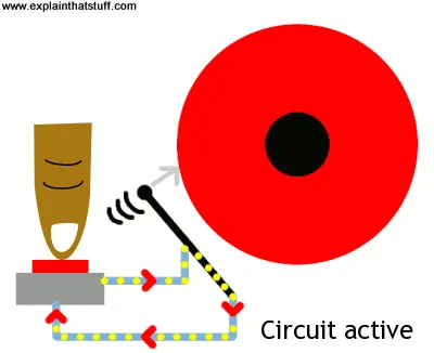
- But , in our study we goin to make Doorbell ring ! with the help of Solenoid and Battery .
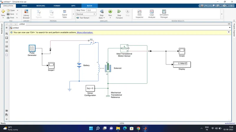
MODEL :
OUTPUT :
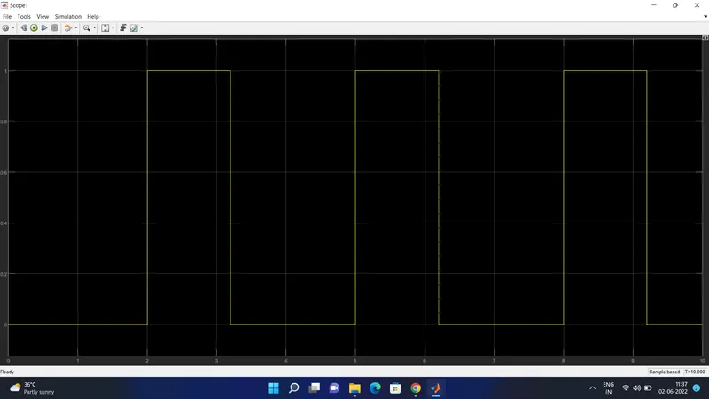
- Hence , the graph represents the time given for the 2 seconds to pulse generator to open and close the switch .
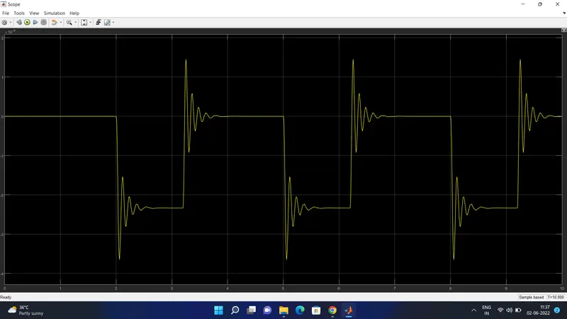
- In the graph the wavelength represents the Vibration when the doorbell rings .
BLOCKS EXPLANATION :
- Pulse Generator : A Pulse generator is used to create the square wave pulse at the regular intervals .The blockwave form parameters ,Amplitude , pulse width , period and phase delay , determine the shape of output waveform .
- Switch Block : The Switch block is controlled by the external physical signal . if the external signal is greater than the tresold parameters then the switch is closed , otherwise the switch is opened.
- BATTERY : The positive terminal (+) of the battery is connected to the switch and negative terminal (-) is connected to the electrical reference .
- SOLENOID BLOCK : The Solenoid block is connected with the switch and battery , hence will get a complete electrical circuit . Then the port is connected with the mechanical reference.
- IDEAL TRANSLATIONAL SENSOR : The ideal translational sensor is connected with the solenoid block to observe the movement of the plunger .
- PS SIMULINK CONVERTER : The PS - simulink converter is used to convert the physical signal to a simulink signal .
- SCOPE : The Scope block usually gives the output from the program which is connected with the ideal translational sensor .
- SOLVER CONFIGURATION (fx) : Each physical network represented by a connected simscape blocks which requires the solver setting information for the simulation .
2. THERMISTOR .
AIM :
- To use a thermistor to sense the temperature of a heater & turn on or turn off the fan.
OBJECTIVE :
-
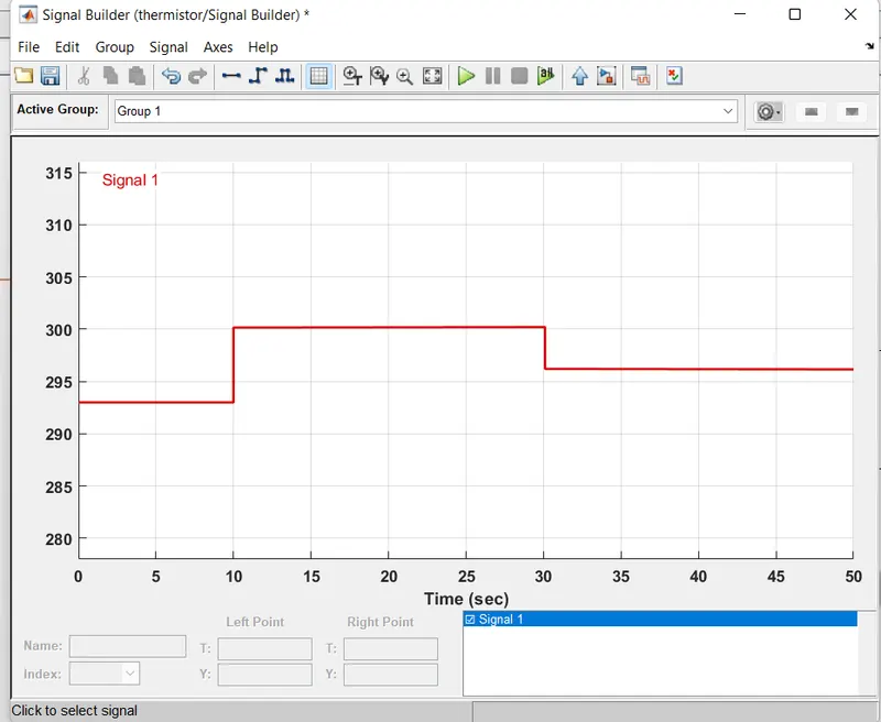
Temperature source: 20 °C from 0 to 10 seconds, 27 °C from 10 to 30 seconds, 23 °C from 30 to 50 seconds
Fan conditions: ON if the temperature above 25 °C, OFF otherwise.
THEORY : THERMISTOR
- A thermistor (or thermal resistor ) is defined as the type of the resistor whose electrical resistance varies with changes in temperature .
- Although all resistor's resistance will fluctance slighty with the temperature , a thermistor is particularly sensitive to temperature changes.
- Termistor act as a passive component in a circuit .
- They are accurate ,cheap and robust way to measure the temperature .
- Thermistor are ideal when a precise temperature reading is required .
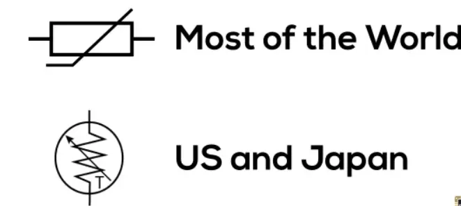
CIRCUIT SYMBOL OF THERMISTOR :
WORKING PRINCIPLE :
- The working principle of thermistor is that its resistance is dependent on the temperature .
- The resistance of the thermistor can be measured using an ohmmeter .
- If we know the exact relationship between how changes in the temperature will affect the resistance of the thermistor , then by measuring the thermistor's resistance we can dervie its temperature .
- The resistance changes depends on the type of material used in the thermistor .
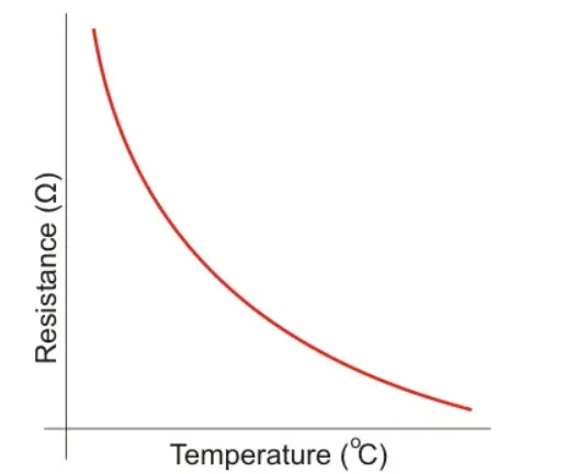
- The relationship between a thermistor's temperature and resistance is non-linear .
- For our better understanding ,a thermistor graph is shown below .
MODEL :
BLOCK EXPLANATION :
- SIGNAL BULIDER : The signal builder block allows to create the interchangeable groups of piecewise linear signal sources and use them in a model . In signal builders the inital conditions is been given respectively from the above equation .
- SIMULINK - PS CONVERTOR : The simulink PS convertor block is used to convert the inputs signals into the a physical signal . In this case before simulating the program , need to provide an intergated input in simulink PS convertor block ,so that can read the system .
- CONTROLLED TEMPERATURE SOURCE : The controlled temperature source block represents an ideal source of the thermal energy that is powerful enough to maintain the specified temperature diffeerence across the source regardless of the heat flow consumed by the system .
- THERMAL REFERENCE : The thermal reference block represents the thermal reference points , a point with absolute zero temperature .
- SOLVER CONFIGURATION : Each physical network represented by a connected simscape block diagram which requires solver settings information for the simulation. The solver configuration block specifies the solver parameters .
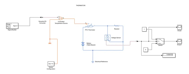
- THERMISTOR : The thermistor block represents both NTC and PTC thermistor . In our study let us consider the PTC thermistor , which senses the temperature with respect to the time .
- BATTERY : Battery block represents the generic dynamic model that represents the most popular types of rechargeable batteries . The + therminal battery is connected to the thermistor .
- VOLTAGE SENSOR : The voltage sensor block represents an ideal voltage sensor ,that is a device converts the voltage measured between two points of an electrical circuit into a physical signal proportional to the voltage .
- PS - SIMULINK CONVERTOR : The PS- convertor block represents the converation of physical signal into a simulink output signal .
- ELECTRICAL REFERENCE : The electrical reference block represents a electrical ground .
- SWITCH CASE : The block represents eternal physical signal .
- CONSTANT : The constant block generates a real or complex constant value signal . use this block to provide a constant signal value .
- DISPLAY : The display block represents the values of the output signal.
- SCOPE : The scope block represents the graphical representation of a simulation .
OUTPUT :
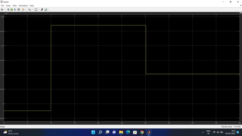
- In this case the graph represents the switch on off condition . If the temperature is above the switch is on and if the temperature is below the switch is off .
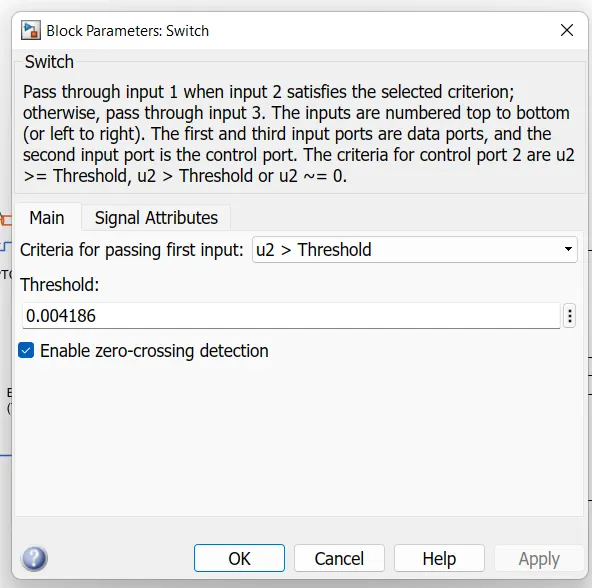
- The thershold value is 0.004186 .
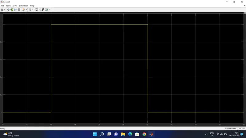
- In the above graph it is clearly shown that, from 0- 10 sec signal is 0 because in this time period the inital condition of temperature is 20 degree celcius , which is below 25 degree celcius . In that casese the fan is switch off .
- From 10- 30 sec , the signal is 1 because the in that time period , the temperature is 27 degree celcius , which is above 25 degree , so in that the fan is Switch on .
- From the 30-50 sec , the signal is again 0 , that the time period the tempreature is 23 degree celcius ,that is below 25 degree , means the switch off .
CONCULSION : The doorbell mechanism and thermistor is done with respcet to the inital conditions .