Project
AIM :
- To carry out the system – level simulation of all – terrain vehicle.
OBJECTIVE :
- To prepare the technical report explaining the model properties and comments on the results.
THEORY : ALL -TERRAIN VEHICLE .
- Modern inventor of all – terrain vehicle is Osamu Takeuchi.
- He named the first all – terrain vehicle as US90. Introduced by HONDA in the year of 1969.
- An all - terrain vehicle (ATV) also known as light utility vehicle (LUV) a quad bike or simply a quad, as defined by the American national standards institute (ANSI) is a vehicle that travels on low pressure tires with a seat that is straddled by the operator, along with handlebars for the steering control.
- As the name implies, it is designed to handle a wider variety of terrain than the other countries.
- The ATV is commonly called a four-wheeler in Australia, South Africa, parts of Canada, India and the United States.
- The rider sits on operates like a Motorcycle, but the extra wheels give more stability at slower speeds.
- The multiple -user analogues with side-by-side seating capacity are called as Utility Terrain Vehicle.
- Depending on the tyre conditions, these all – terrain vehicle can travel on the land snow swampland.
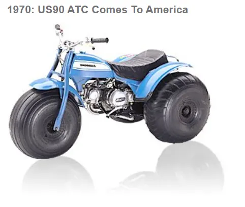
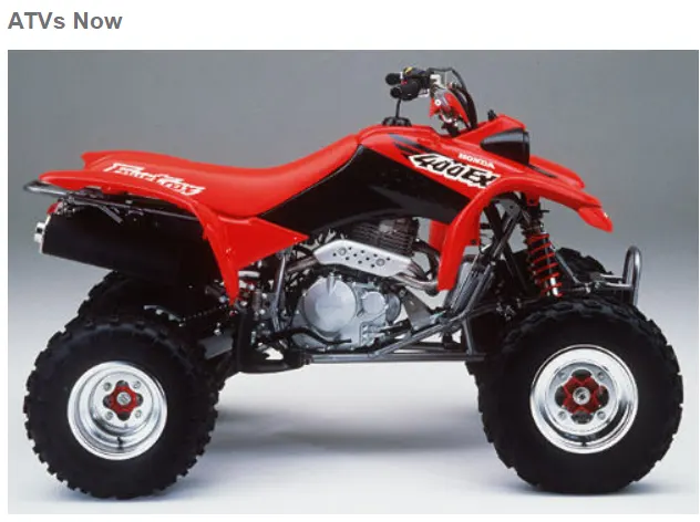
- From the above images we can clearly able to see the first framed All-terrain vehicle model which is 19th century and at right-side image is the current 21st century of modern all – terrain vehicle.
MECHANISM : ATV How do they work .
- TRANSMISSION : The mechanism by which power is transmitted from an engine to the axle in a motor vehicle .
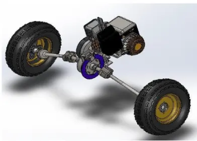
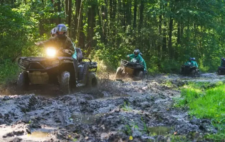
- All terrain – transmissions are mostly
- Manual transmission
- Semi-automatic transmission
- Automatic transmission
- For example, some of the transmission will shift from two-wheel to four-wheel drive or go from high to low gear, depending on the situation.
MANUAL ATV TRANSMISSION :
- In ATVs with a manual transmission, you have to choose the best gear for the situation.
- In manual transmission setup, the operator need to disengage the engine from the transmission using the clutch stick before shifting between gears. Once the gear is locked in, need to re-engage the engine by releasing the clutch.
- So, in the manual transmission, you have to control the clutch, the gear lever, and the throttle, If the condition is on the hill region, brakes must be applied.
SEMI-AUTO ATV TRANSMISSION :
- ATVs with semi-auto transmission are similar to those with a manual transmission, but the main difference is in the operation of the clutch.
- In this case, have to choose the optimum gear for the scenario, where the clutch doesn’t have a sperate lever. The act of shifting gears automatically controls the clutch as well.
- With this setup, have one less thing to worry about while staying in control of the power generated by the engine.
- This type of transmission is very popular with sport ATVs
AUTOMATIC TRANSMISSION :
- ATVs with automatic transmission are designed to handle gears selection for you, with the right gear chosen at the right time.
- This type of transmission is popular in utility ATVs, where the focus is more on the reason for riding the ATVs, such as hauling, towing, or plowing.
ATV MAINTENANCE :
- Usually engines are the most expensive parts to replace in the ATVs, To rectify this the following conditions are applied .
- Inspect and replace the oil as needed.
- Use high-quality fuel.
- Clean the air filter
- Pay attention to all of the fluids.
- Store the ATVs properly.
USES :
- All-Terrain vehicle (ATV) are widely used in the agriculture, forestry, entertainment, and military fields because of their excellent passing performance.
- ATVs uses low pressure wide tires making it easy to shuttle through harsh terrains such as sand and riverbeds.
MODEL :
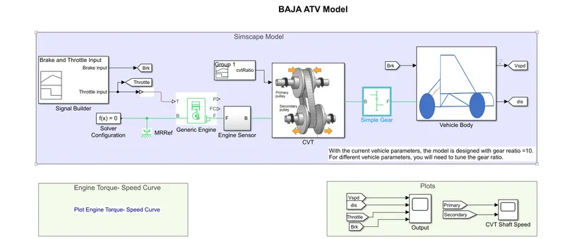
- Earlier we discussed about varies types of transmission used in ATVs, in this particular model BAJA ATV, Continuous Variable Transmission (CVT) is used.
- Let us discuss briefly about continuous variable transmission.
CONTINOUS VARIABLE TRANSMISSION (CVT):
- A continuously variable transmission (CVT) is an automatic transmission that can change seamlessly through a continuous range of gear ratios.
- This contrasts with other transmissions that provide a limited number of gear ratios in fixed steps.
- The flexibility of a CVT with suitable control may allow the engine to operate at a constant RPM while the vehicle moves at varying speeds.
- CVT are used in automobiles, tractors, motor-scooters, snow-mobiles, bicycle-sand earthmoving equipment.
- The most common CVT have three components, they are
- A high-power metal or rubber belt.
- A variable-input “driving” pulley.
- An output “driven” pulley.
- CVTs also have various microprocessors and sensors, but the three components described above are the key elements that enable the technology to work.
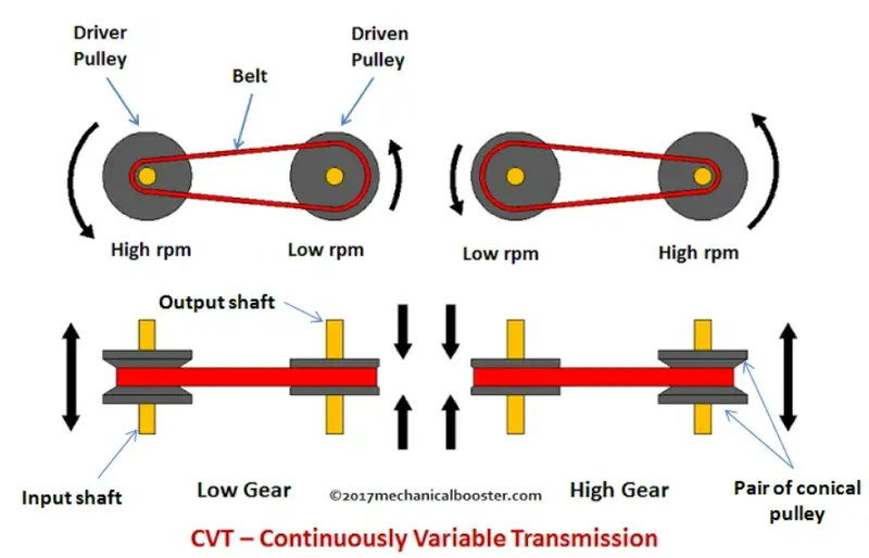
- The Variable-diameter pulley are the heart of a CVT.
- Each pulley is made of two 20-degree cones facing each other.
- A belt rides in the groove between the two cones. When two cones of the pulley are far apart (when the diameter increases), the belt rides lower in the groove, and the radius of the belt loop going around the pulley gets smaller.
- When the cones are the closer together (when the diameter decreases), the belt rides higher in the groove, and the radius on the belt loop going around the pulley gets larger.
- Variable-diameter pulley must always come in pairs.
- One of the pulleys, known as the drive pulley (driving pulley), is connected to the crankshaft of the
- The driving pulley is also called as the input pulley because it’s where the energy from the engine enters the transmission.
- The second pulley is called as driven pulley because the first pulley is turning it.
- As the output pulley, the driven pulley transfers to the driveshaft. That’s how the transmission of CVTs works.
- The introduction of new materials makes CVTs even more reliable and efficient.
- One of the most important advances has the design and development of the metal belts to connect the pulleys. Metal belts don’t slip and are highly durable, enabling CVTs to handle more engine torque.
BENEFITS OF CVTs :
- Eliminates “shift shock” – makes for a smoother ride.
- Improved fuel efficiency.
- Better control of emissions.
- Better torque Ratio.
Apart from CVT, there are other main function used in the BAJA all – terrain model. Let us discuss step by step of each function.
- Generic Engine.
- Simple Gear.
- Variable Ratio Transmission.
- Vehicle Body.
- Double Shoe Brake,
- Tire.
- Engine Sensor.
- GENERIC ENGINE :
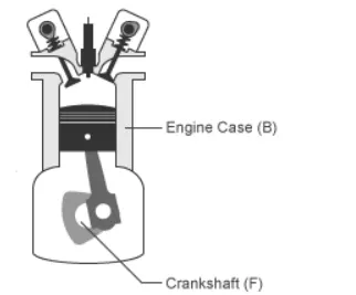
- Generic engine block represents the general internal combustion engine.
- This block is a suitable generic engine for Spark-ignition and Diesel.
BLOCK :
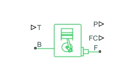
PORTS :
- INPUT.
T (Physical Signal) – Normalized engine throttle level, Unitless.
- OUTPUT.
P (Physical Signal) – Instantaneous engine power, W.
FC (Physical signal) – Fuel Consumption rate, kg/s.
- CONSERVING.
B (Mechanical Rotational) – Engine Block.
F (Mechanical Rotational) – Engine Crankshaft.
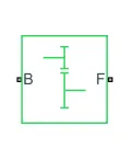
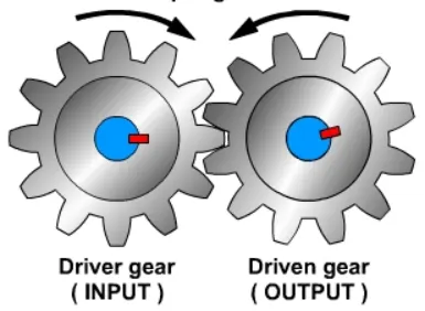
- SIMPLE GEAR : simple gear represents the gear box that constrains the connected driveline axes of the base gear B, and the follower gear F, corotate with the fixed ratio that you specify.
BLOCK :
PORTS :
- INPUT.
T (Physical Signal) – External fault trigger.
- CONSERVING.
B (Rotational Mechanical) – Base Gear.
F (Mechanical Rotational) – Follower.
H (Thermal) – Heat Flow.
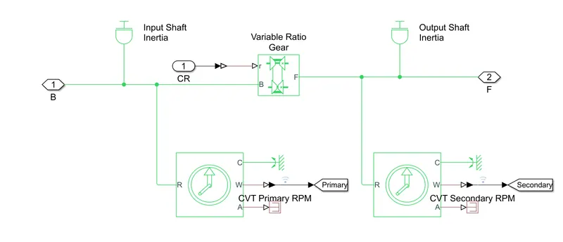
- VARIABLE RATIO TRANSMISSION :
BLOCK :
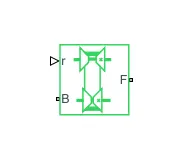
- The variable ratio transmission block represents a gear box that dynamically transfers motion and torque between the two connected driveshaft axes, the base and the follower.
- Transmission compliance introduces internal time delay between the axis motions.
PORTS :
- INPUT.
r (Physical signal) – Input -to-output shaft velocity ratio, Unitless.
- CONSERVING.
B (Mechanical Rotational) – Base driveshaft.
F (Mechanical Rotational) – Follower driveshaft.
- VEHICLE BODY :
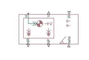
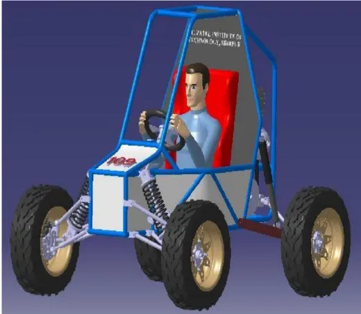 3D View of Vehicle Body
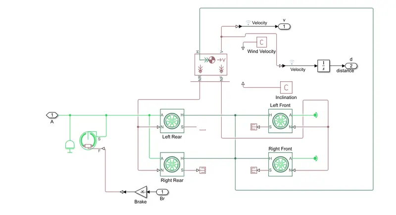
- The vehicle body represents a two – axe vehicle body in longitudinal motion.
- The vehicle can have the same or a different number of wheels on each axle.
- For example, two wheels on the front axle and one wheel on the rear axle.
- The vehicle wheels are assumed identical in Size.
- The vehicle can also have a center of gravity (CG) that is at or below the plane of travel.
LIMITATIONS AND ASSUMPTIONS :
- The Vehicle Body block lets you the model only longitudinal dynamics, parallel to the ground and oriented along the direction of the motion.
PORTS :
- INPUT.
W (Scalar) – Headwind speed, m/s
Beta (Scalar) – Road incline angle, rad
CG (Two-element vector) – Center of gravity, m.
- OUTPUT.
V (Scalar) – longitudinal Velocity, m/s
NF (Scalar) – Front axle normal force, N
NR (Scalar) – Rear axle normal force, N.
- CONSERVING.
H (Mechanical translational) – Horizontal motion.
- DOUBLE SHOE BRAKE :
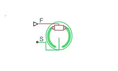
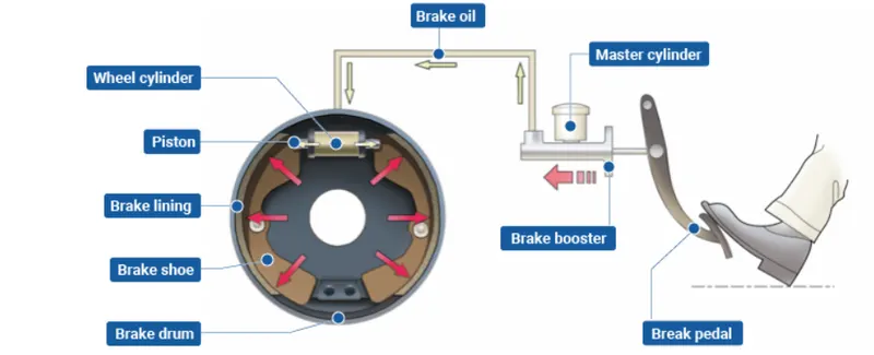
- The Double Shoe brake block represents a frictional brake with two pivoted rigid shoes that press against a rotating drum to produce a braking action.
- The rigid shoe sits inside or outside the rotating drum in a diametrically opposed configuration.
- A positive actuating force causes the rigid shoes to press against the rotating drum.
- Viscous and contact friction between the drum and the rigid shoe surfaces causes the rotating drum to decelerate.
LIMITATIONS AND ASSUMPTIONS :
- Contact angles smaller than 45degree produces less accurate results.
- The brake uses the long-shoe approximation.
- The model does not account for the actuator flow consumption.
PORTS :
- INPUT.
F (Physical Signal) – Actuating Force.
T (Physical Signal) – External Fault Trigger.
- CONSERVING.
S (Rotational Mechanical) – Drum shaft rotation.
H (Thermal) – Heat flow.
- TIRE :
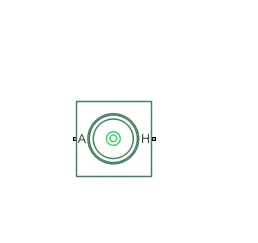
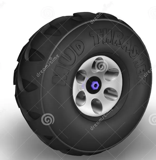
- The vehicle body is connected to 4 tires each per axle to move the vehicle according to the power input to the axle.
LIMITATIONS AND ASSUMPTIONS :
- The tire does not slip.
- Torque-transfer capability is infinite.
PORTS :
- CONSERVING.
A (Mechanical Rotational) – Axle.
H (Mechanical Translational) – Hub.
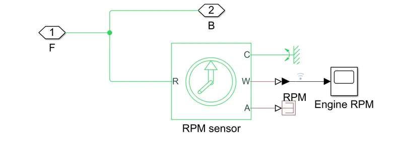
- ENGINE SENSOR(ROTATIONAL MOTION SENSOR) :
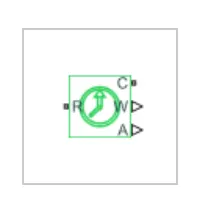
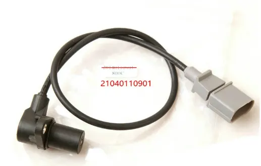
- The Ideal Rotational Motion Sensor block represents an ideal mechanical rotational motion sensor, that is, a device that converts an across variable measured between two mechanical rotational nodes into a control signal proportional to angular velocity or angle. You can specify the initial angular position (offset) as a block parameter.
PORTS :
- OUTPUT.
W (Physical Input) - Angular velocity, rad/s.
A (Physical Input) - Angular displacement, rad.
- CONSERVING.
R (Mechanical Rotational) - Rod (Positive probe).
C ( Mechanical Rotational) - Case (Reference probe).
BLOCK'S EXPLANATIONS :
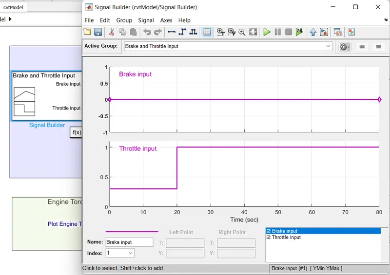
- Signal Builder :
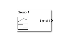
- To input the brake, throttle and CVT ratio.
- Simulink PS – Convertor : To convert the Simulink signal to Simscape environment.
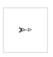
- Solver Configuration : To specify the solver parameters before starting the simulation.
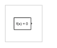
- Mechanical Reference : To make sure all the components are clamped to the ground.

- Generic Engine : To run the engine with the speed and torque values as the input.
- PS-Simulink Convertor : To convert the Simscape signal to Simulink environment.
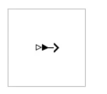
- Scope : To view the graph of parameters for the better understanding.
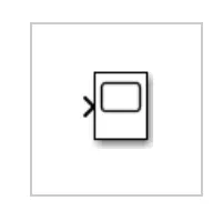
- Display : To view the calculated engine power.
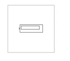
- Inertia : To represent the solid inertia.
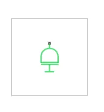
- Rotational Motion Sensor : To sense the rotational motion from the engine and give output as RPM.
- Variable Gear ratio: To vary the speed according to the gear ratio.
- PS Terminator : Terminator for unconnected physical signal outputs.
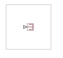
- Double Shoe brake : To apply brake to the vehicle when needed.
- Tire : For transportation of the vehicle .
- Rotational Free End : For mechanical system.
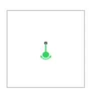
- Vehicle Body : To represent the BAJA ATV model.
- Custom Measure Guage : To measure the brake and throttle input.
- Knob : To increase, decrease and vice – versa of throttle and brake input.
- Lookup Table : To insert the CVT values from the workspace.
- Simple Gear : To reduce the speed of the engine with pre-defined gear ratio.
- Step: To increase or decrease an input value for a defined time interval.
- In our case, models consists of 3 types .
TYPES OF MODEL :
- BAJA ATV model without Dashboard.
- BAJA ATV model with Dashboard.
- BAJA ATV model - Mapped lookup Table with Dashboard.
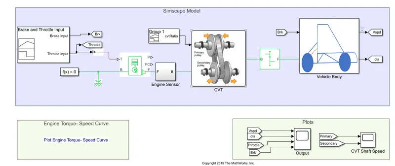
BAJA ATV MODEL WITHOUT DASHBOARD.
- ENGINE SENSOR SUBSYSTEM .
- CVT SUBSYSTEM.
- VEHICLE BODY SUBSYSTEM.
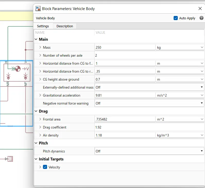
- VEHICLE BODY PARAMETERS.
WORKING :
- With the help of the Signal Builder the Throttle Inupt is generated .
- The inital throttle input is 0.3 for first 0 to 20 secs, and the throttle reamains constant with the speed of 1 from 20 to 80 secs .
- Tho the throttle inuput is generated , Brake input remains constant throughout the simulation process is done that is ( from 0 to 80 sec) .
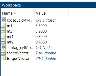
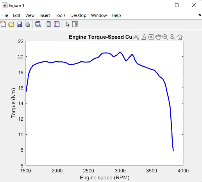
- The Speed Vector and Torque vector is labled from the Workspace.
- WORKSPACE .
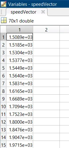 Speed Vector.
 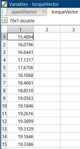 Torque Vector.
- OUTPUT.
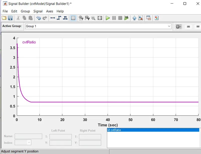
- CVT Ratio.
- RESULT.
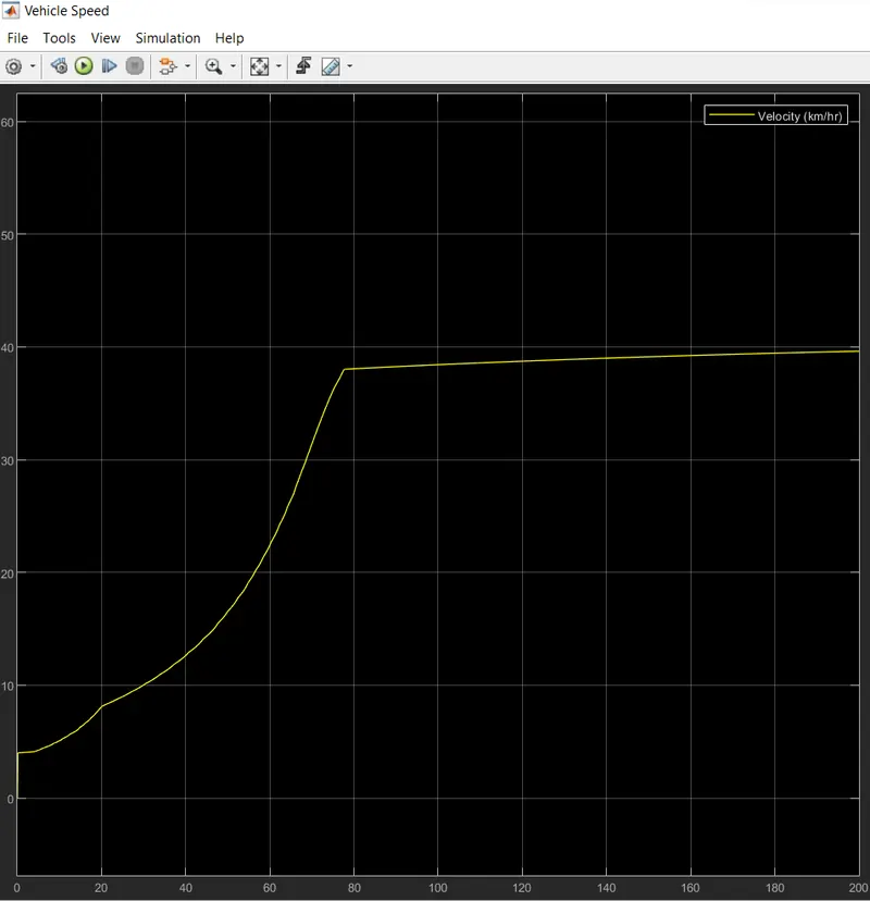
- RESULT.

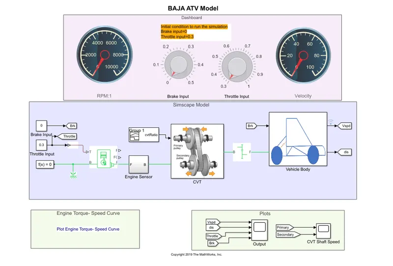
BAJA MODEL WITH DASHBOARD.
- MODEL.
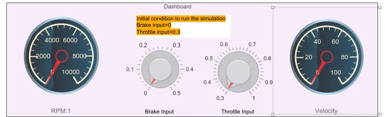
- DASHBOARD.
- WORKING.
The model workflow process is as same as the process of BAJA ATV model without Dashboard, but the throttle and brake input are controlled by the user with the knob.constant block is used in this process instead of the signal builder where we used in the previous model.
- KNOB.
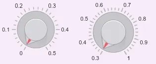
- The difference between pervious model and this model is that the trottle and brake inputs are given as a graphical representation. In this model the simulation process is an infinite peroid,so that the show the various inupt.
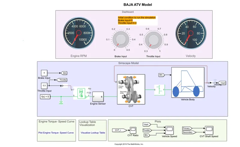
BAJA MODEL WITH LOOK UP TABLE .
- MODEL.
- DASHBOARD (SIMULATION OFF).
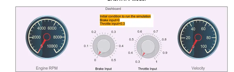
- It is in the idle condition.
- DASHBOARD (SIMULATION ON).
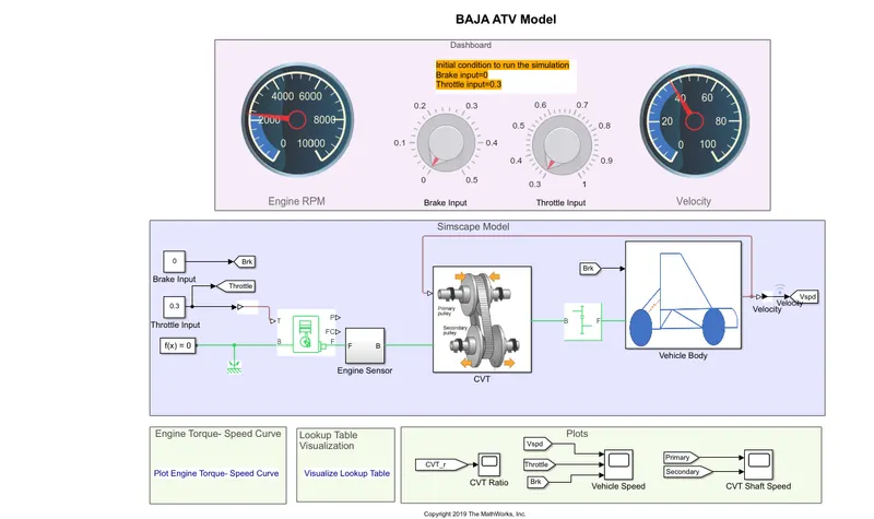
- WORKING.
The workflow process is same as the BAJA ATV model with the dashboard.
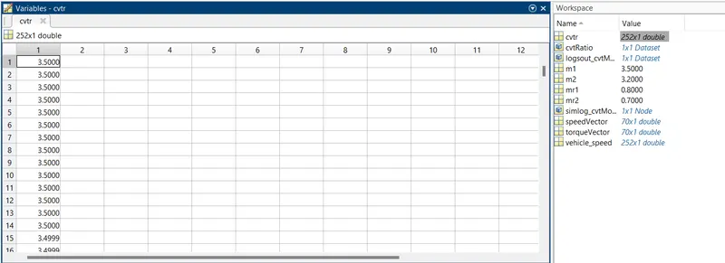
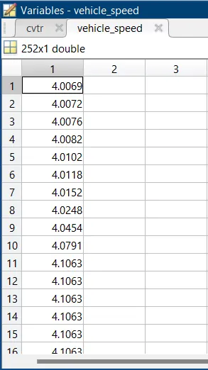
The CVT ratio and Vehicle speed is been extracted using the 'To workspace' block.
- Vehicle speed.
- Lookup table parameters .
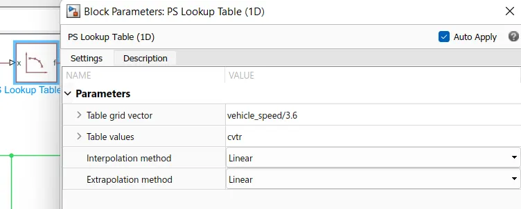
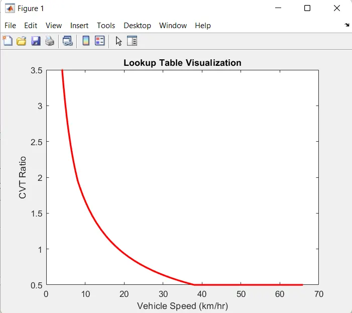
In this case 1D lookup table is used instead of Signal builer . Parameters of the lookup table , the interpolation and extrapolation methods are set to be linear.
- Lookup table Visualization .
CONCULSION :
- With the help of simulink model BAJA ALL TERRAIN ATV model, The following the types of CVT model , with DASHBOARD, and LOOKUP TABLE model is done .