Week 6 - CHT Analysis on a Graphics card
AIM:-
- Perform a Steady-State Conjugate Heat Transfer analysis on a graphic card using ANSYS-FLUENT.
OBJECTIVES:-
- To run the Simulation by varying the velocities from 1m/s to 5m/s for atleast 3 velocities.
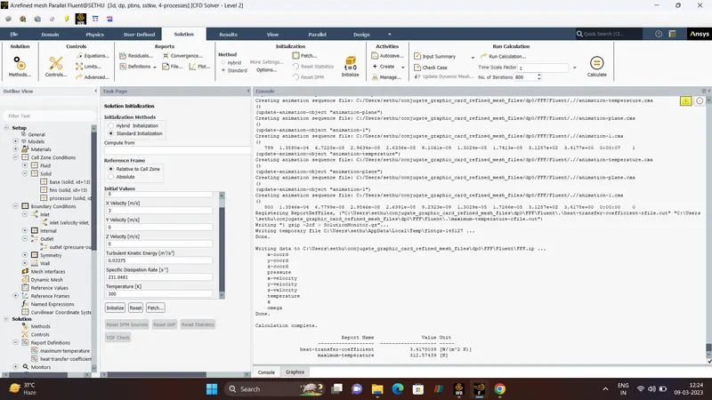
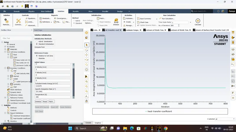
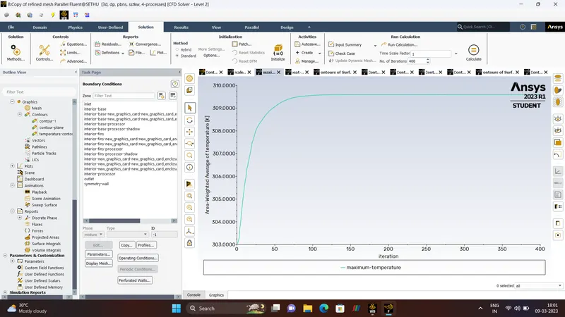
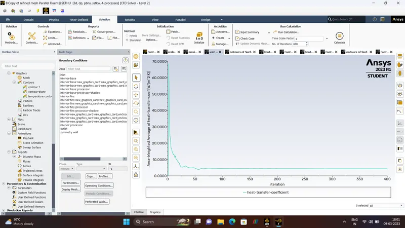
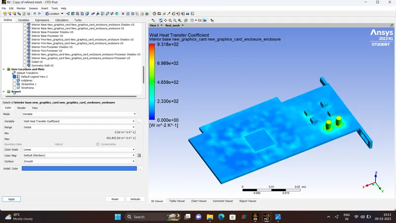
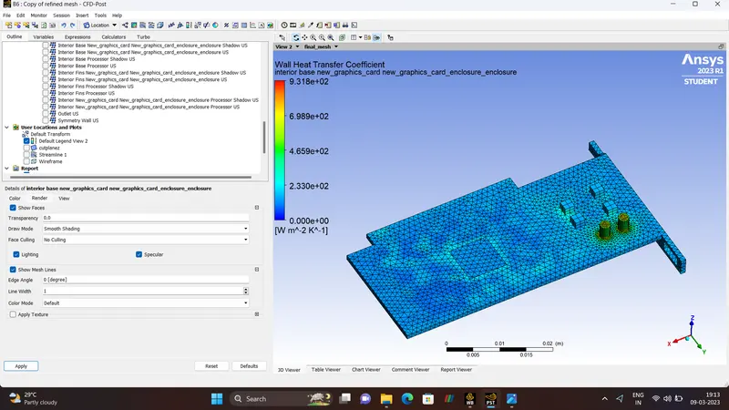
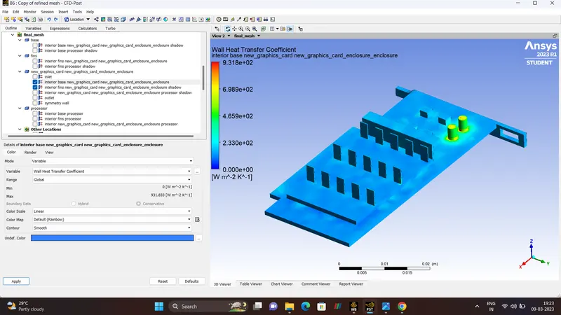
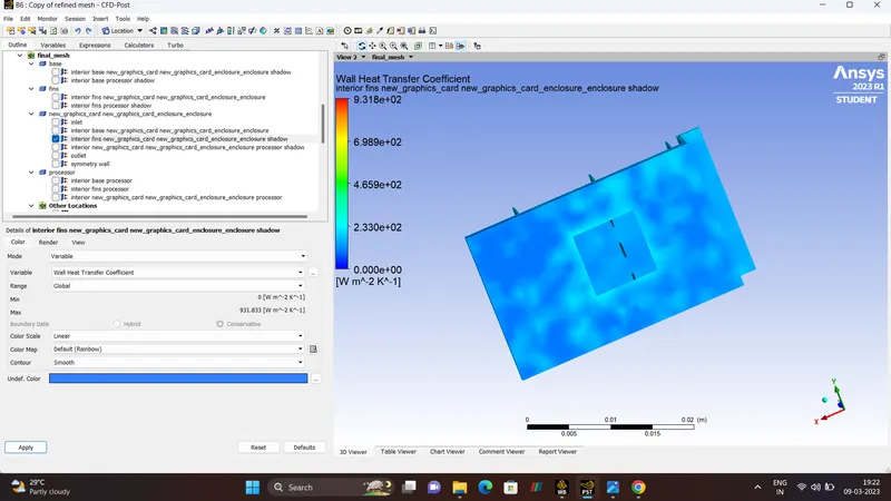
- To find out maximum temperature and heat transfer co-efficient attained by the processor.
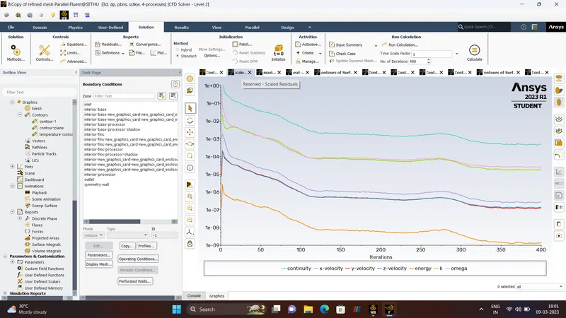
- To prove that the simulation has achieved the convergence criteria.
- Identify the potential hotspots.
PROCEDURE:-
CONJUGATE HEAT TRANSFER.
ABSTRACT.
This Project is about Simulation of Steady-State Conjugate Heat Transfer on a Graphic Cards using ANSYS_FLUENT. Graphics card is a itegrated circuit that generates the video signals sent to computer display, the card is usually located in the computer motherboard or is separated circuit board which built inside the computer itself. The Graphics Card consists of Processors, Fins, Base,Enclosure. In our project Simulation going to be run through the three different velocities and Temperature and Heat Transfer Co-effiecient on a graphic card is to be monitor.
INTRODUCTION.
- Conjugate Heat Transfer is a concept of heat transfer involed in both fluids and solids simultaneously.
- For Solving Conjugate Heat Transfer problems, we use both the Conduction and Convection Equations for the revelant phase of material.
- Conjugate Heat Transfer corressponds with the combination of Heat Transfer in Solids and Fluids.
- In Solids, the Conduction Often dominates Whereas in Fluids, the Convection often dominates.
- Common applications and uses cases of this simulationtupe include Electronics Cooling, Heat Exchanges, Industrial Machinery, Heaters, some AEC cases etc.
- Conjugate Heat Transfer provides the temperature and the Hotspot region at the solids, fluids interface and we can also predict the heat transfer accurately for example conduction through solids, convection through fluids and thermal radiation. It also provides the velocity and pressure distribution of fluid moving inside the solids. we can also use CHT in design optimization for improvement for heat transfer and cooling capacity.
- CONJUGATE HEAT TRANSFER APPLICATIONS.
Effective Heat Transfer.
- Efficiently combining heat transfer in fluids and solids is the key to designing effective coolers, heaters or heat exchanges. The fluid usually plays the role of energy carrire on large instances. Forced convection is the most common way to achieve high heat transfer.
Energy Savings.
- Heat transfer in fluids and solids can be combined to minimize heat losses in various devices, because most gases(especially at low pressure) have small thermal conductivities, they can be used as thermal insulation.
Electromobility.
- Effective cooling strategies are critical for various components of emobility system. Electric motors, have high power densities and thus generate a significant amount of heat. If a motor is not properly cooled, high temperature in the motor can cause the demagnetization of permanent magnets and breakdown of windings modulation.
ADVANTAGES OF CONJUGATE HEAT TRANSFER.
- The Conjugate Heat Transfer replaces the empirical relation of propontionally of HEAT FLUX to TEMPERATURE difference with Heat Transfer Co-efficient. The Wall Heat Transfer Co-efficient and their local variations are directly computed within the model and do not involve the solving of complex empirical relations. Thus the Simulation are carried out much faster.
- As long as the Boundary Conditions are accurately defined, the solution are highly accurate due to simplicity of the conjugate heat transfer model.
- There is no, limit for the number of surface and hence can be applied for a large number of region in a given assembly.
- Since the conjugate heat transfer model is a combination of heat transfer in both a solid and fluid model it can be applied for all combination of interaction.
HEAT TRANSFER.
Heat transfer is defined as the movement of heat across the border of the system due to a difference in temperature between the system and it's surroundings.
HOW HEAT TRANSFERRED?.
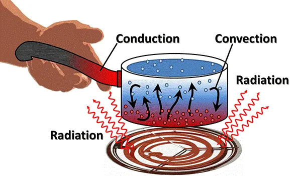
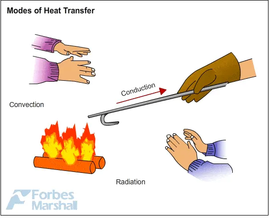
- Heat can travel from one place to another in serval ways, They include
1. Conduction.
2. Covection.
3. Radiation.
- If temperature difference exist between two system, heat will find a way to transfer from the higher system to the lower system.
CONDUCTION.
Conduction is defined as the process of transmisson of energy from one particle of medium to another with particles beings in direct contact with each other.The Conduction equation is expressed as,
| `Q = (K *A*(T_(hot)-T_(cold)))/d` |
The Co-efficient of the thermal conductivity shows that a metal body conducts heat better when it comes to conduction.
| Q | Heat Transfer per unit Time |
| K | Thermal Conductivity of the Body |
| A | Area of Heat Transfer |
| `T_(hot)` | Temperature of the Hot Region |
| `T_(cold)` | Temperature of the Cold Region |
| d | Thickness of the Body |
CONVECTION.
Convection is defined as the movement of fluid molecules from Higher temperature region to Lower temperature region.The Convection equation expressed as,
| `Q = h_c *A*(T_s -T_f)` |
| Q | Heat Transfer per unit Time |
| A | Area of Heat Transfer |
| `T_s` | Surface Temperature |
| `T_f` | Fluid Temperature |
HEAT TRANSFER COEFFICIENT.
Heat Transfer Co-efficient also known as Film Co-efficient or Film Effectiveness, is a measure of non-dimensionality for understanding the increase in temperature of flow by a degreee when certain heat supplied to the flow over the cross-section of the flow. It signifies the heat transfer of heat between a fluid medium and to surface flowed over by the fluid.
| `h = q/(delT)` |
| h | Heat Transfer Co-efficient of the flow `W/(m^2-k)` |
| q | Heat Flux `W/m^2` |
| `delT` | Diff in Temp between Solid Surface and Fluid Area, Kelvin(K) |
GRAPHICS CARD.
INTRODUCTION.
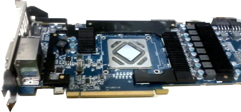
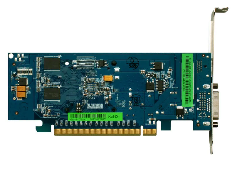
A Graphic Card (also called video card, display card, graphic adpator, VGA card/VGA,Video adaptor, display adaptor is a computer expansion card that generates a feed of graphic Output to a display device such as monitor. Graphic card are sometimes called discrete or dedicated graphic card to emphasize their distinction to integarted graphic processor on the motherboard or the CPU. A graphics Processing Unit that performs the necessary computation is the main component in a graphic card, but the acronyum "GPU" is sometime also used to refer to the graphic card as a whole.

BASE.
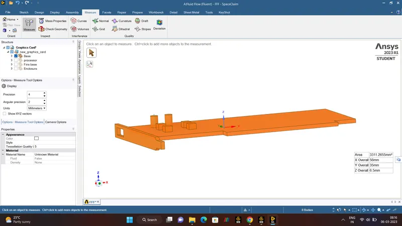
Base is made up of PCB with some mixed material coating like glass, rasin, copper for electric flow. This is mostly made up of plastic like material and having copper wires in it to flow the current through it to semi-conductor and processor which we installed on it and to avoid any problem the coating of glass is kept on that.
FINS.
Fins are provided on base plate at the top of processor to provide the cooling effect to graphic card because the main part that creates the heat is processor to thefins are provided on the top of it.
PROCESSOR.
Processor is important component on graphic card the component which is 80 percentage working component in graphic card and as we say above it create the excessive temperature which heat up the graphic card and also can damage graphic card if not cooled.
SIMULATION
- GEOMETRY.
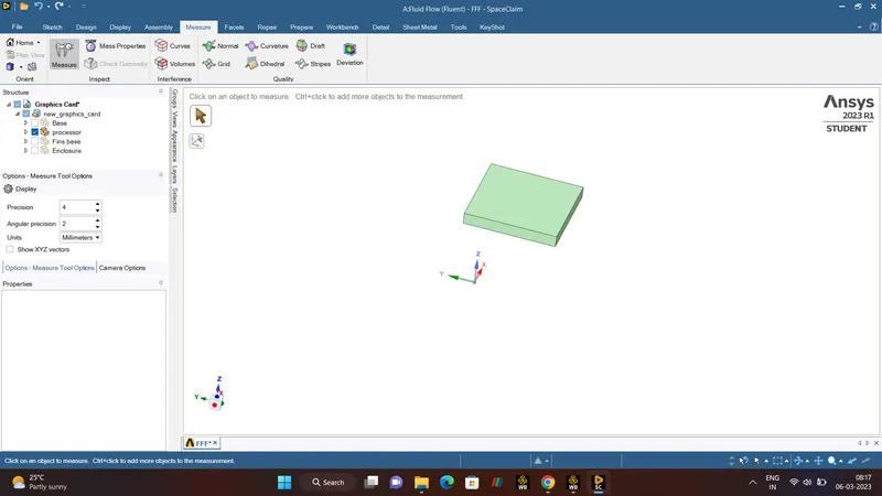
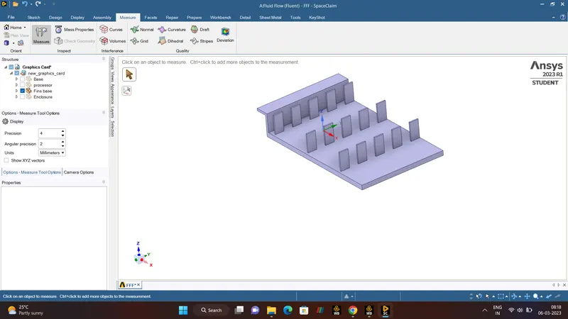
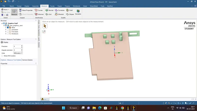
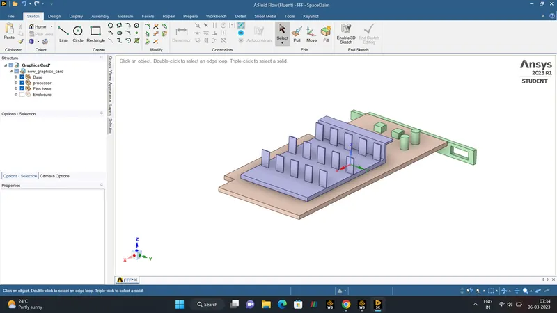
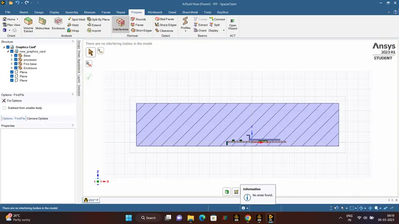
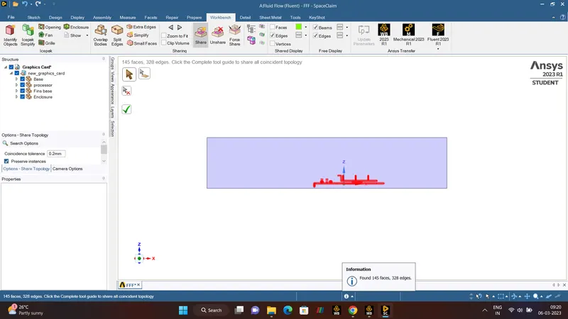
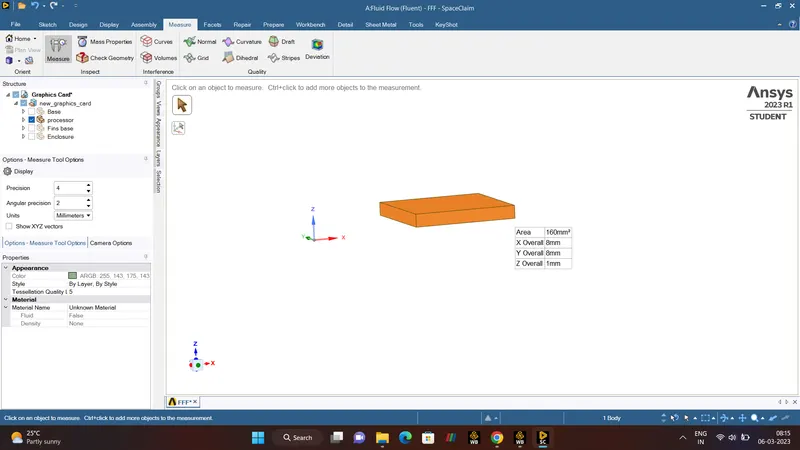
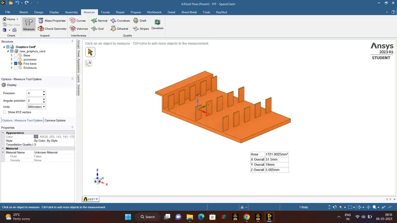
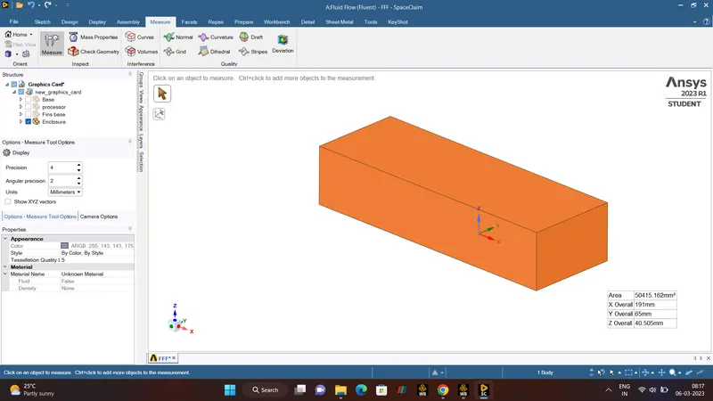
To run the Simulation Of Conjugate Heat Transfer on a Graphic Card in ANSYS-FLUENT, First need to Use the SPACECALIM from Ansys Workbench. With the Use of Spaceclaim Import the Graphic Card model. The following model consists of Base, Processor, Fins, Enclosure.
- SHARE TOPOLOGY.
The purpose of Share Topology Operation is to ensure that connected bodies have Shared faces, which helps facililate the creation of Conformal Mesh. Often, this operation is performed at very end of CAD creation phase before the geometry is passed over for meshing.
- MESHING.
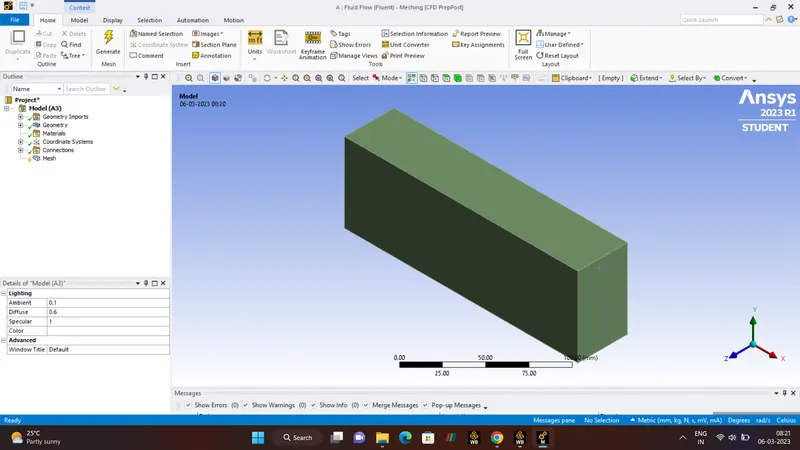
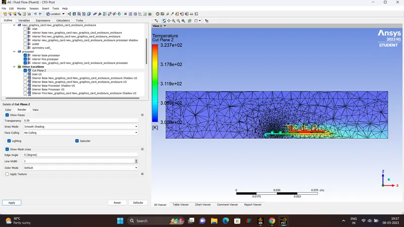
A Mesh is a network that is formed of cells and points. It can have almost any shape in any size and is used to solve the PDEs (Partial Differential Equation). Each cell of the mesh represent an individual solution of equation which, when combined for the whole network, results in a solution for entire mesh.
Why do we need Mesh?
Solving the entire object without dividing it into smaller pieces can be impossible because of complexity that is within the object. Holes, comes and angles can make it exteremly difficult for solvers to obtain solution. Small cells, on the other hand are comparably easy to solve and therefore preferred strategy. The PDEs is solved in each and every individuals cells. Hence each cell holds a local solution of discretised equation which is then combined together to develop a global solution.
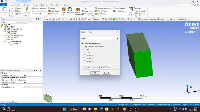
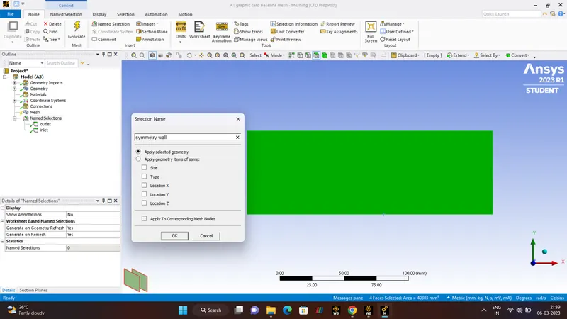
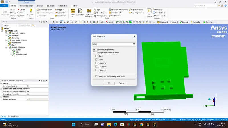
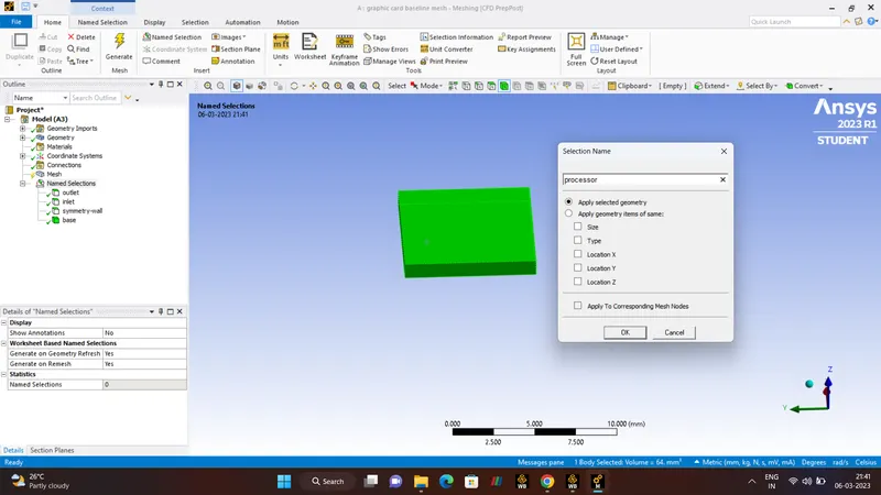
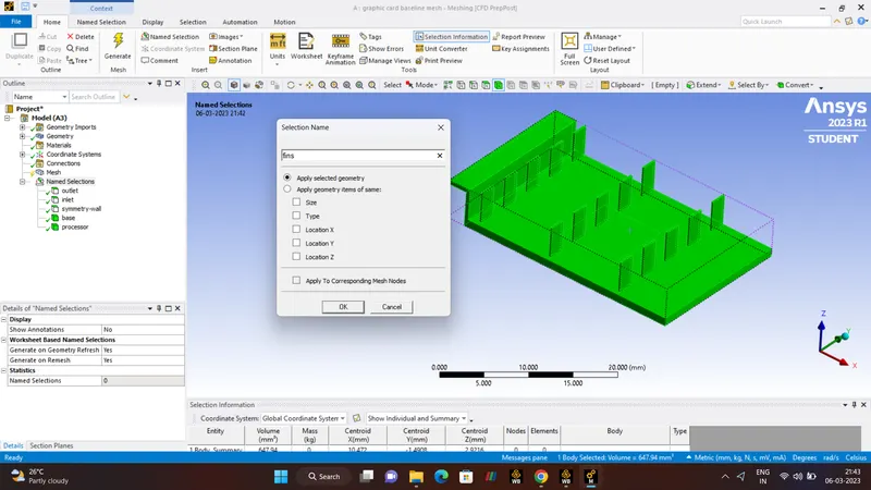
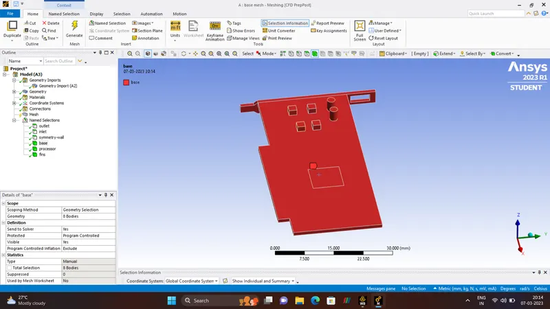
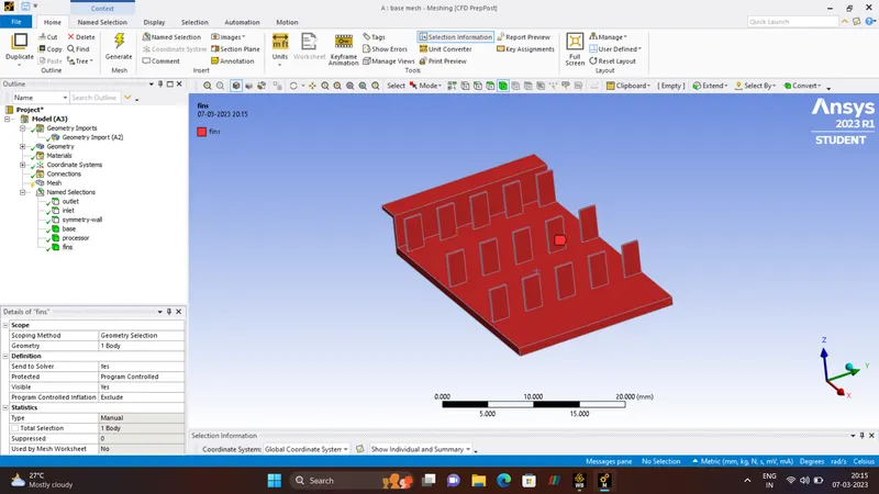
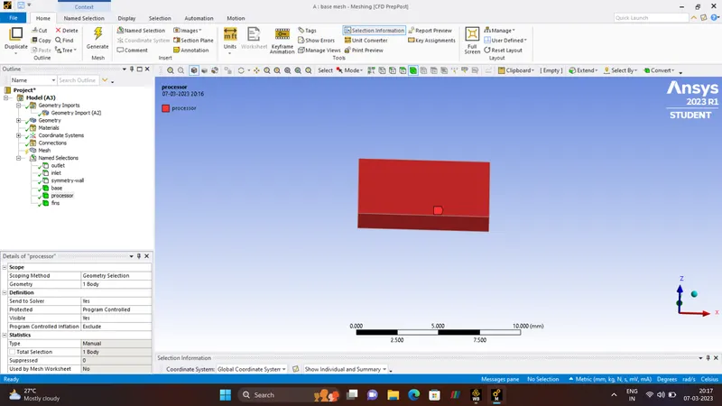
- NAME SELECTION.
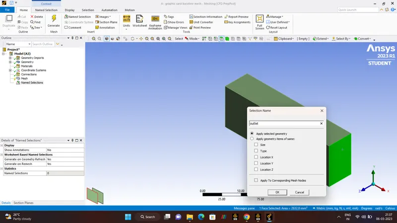
1. INLET
2. OUTLET
3. SYMMETRY-WALL
4. BASE
5. PROCESSOR
6. FINS.
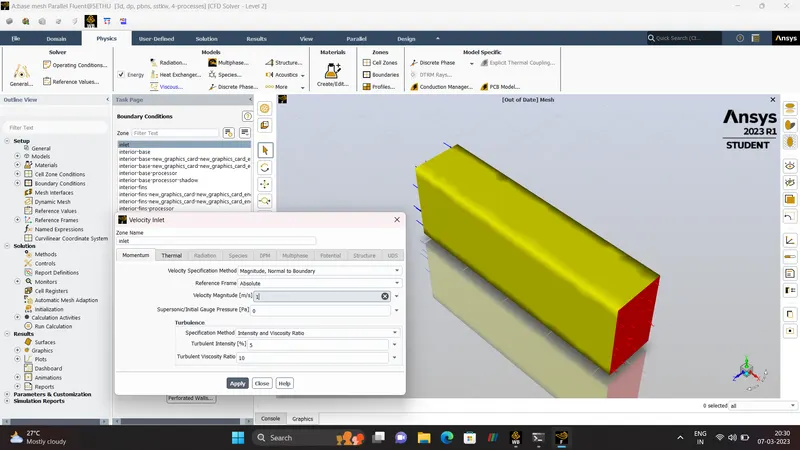
- BOUNDARY CONDITION.
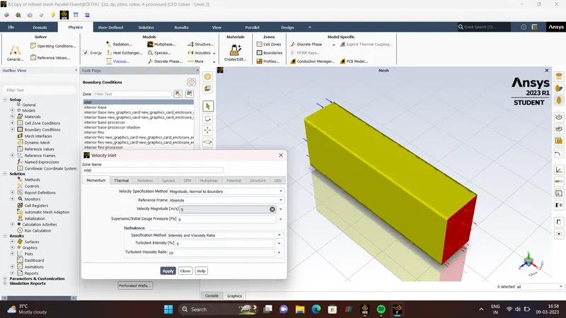
Boundary Condition pertain to the field of computational mechanics where we initialize the study with certain conditions. When we translate the problem to the computational domain, we assign different conditions to diiferent aspects of the domain. In layman's term, boundaries represent the physical bound and different components of computational domain which we initialize the study. We patch values of the certain flow properties on these boundaries, for instance it can be VELOCITY/PRESSURE/TEMPERATURE etc. Through which can start the iterative process of solving the problem.
- SIZING.
| BASE MESH | 8mm |
| FINS | 5mm |
| BASE | 5mm |
| PROCESSOR | 5mm |
| NUMBER OF NODES | 16388 |
| NUMBER OF ELEMENTS | 87037 |
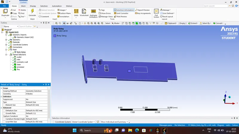
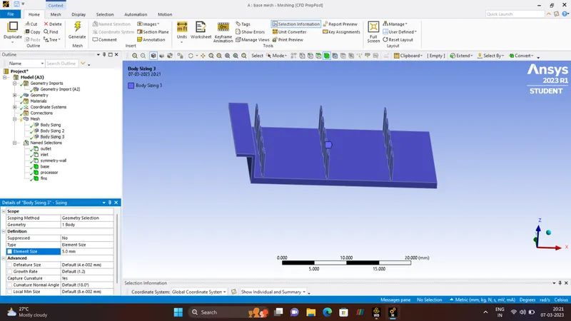
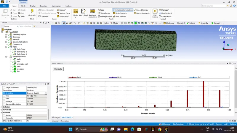
- SETUP.
| SOLVER | PRESSURE_BASED_SOLVER |
| SIMULATION | STEADY_STATE |
| ENERGY | ON |
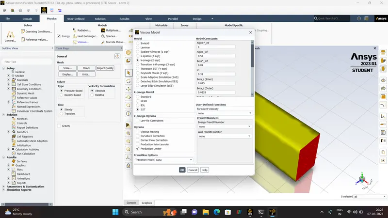
| VISCOUS MODEL | K-OMEGA MODEL |
K-OMEGA MODEL.
- K is Turbulent Kinetic Energy.
- OMEGA is the Rate Of Dissipation Of Turbulent Energy Per Unit Area.
STEADY-STATE.
- In CFD simulation, a Steady_State is Considered when all the flow properties like Temperature, Pressure, Velocity are constant.
- Steady_State Simulation computes the fully developed solution that does not change in Time.
- When Steady_State are used mean values are computed.
- Steady_State are way faster than the Transient_State Simulation.
PRESSURE-BASED SOLVER.
- Pressure Based Solver was developed for 'LOW-SPEED-INCOMPRESSIBLE' Flow (M<0.3) and midly Compressible Flow. This Solver uses Momentum and Pressure as their primary variables
MATERIALS
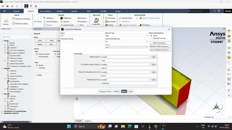
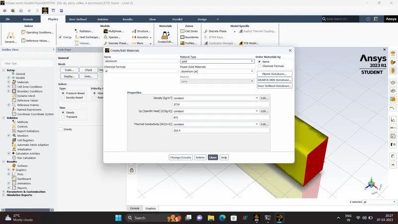
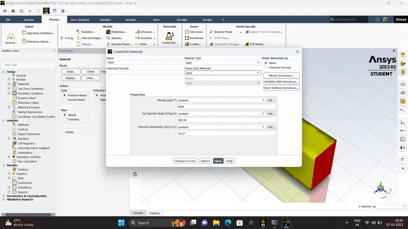
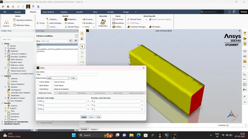
| FLUID | AIR |
| FLUID | SOLID |
| SOLID_1 | FINS |
| SOLID_2 | PROCESSOR |
| SOLID_3 | BASE |
AIR
| DENSITY | 1.225 (kg/m^3) |
| Cp(SPECIFIC HEAT) | 1006.43 (J/kg_k) |
| THERMAL CONDUCTIVITY | 0.0242 (W/mk) |
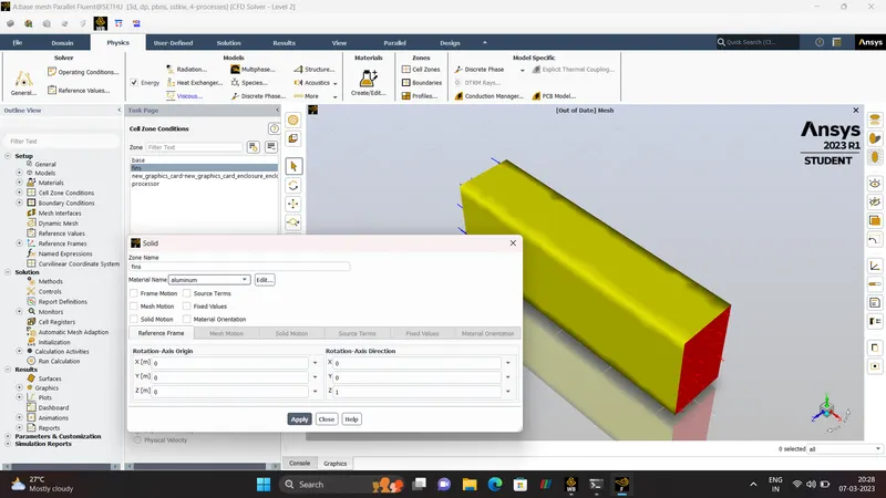
FINS-(ALUMINUM)
| DENSITY | 2719 (kg/m^3) |
| Cp(SPECIFIC HEAT) | 871 (J/kg_k) |
| THERMAL CONDUCTIVITY | 202.4 (W/mk) |
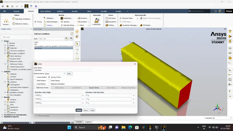
PROCESOR-(SILICON)
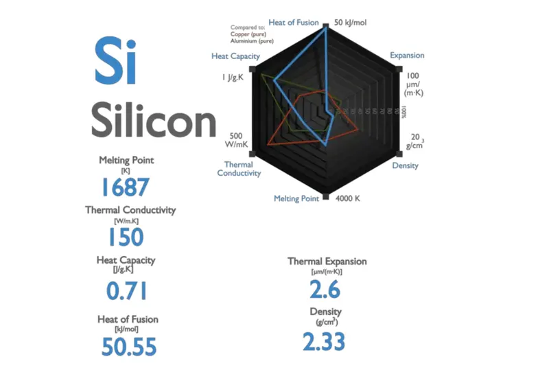
- For SILICON need to create a USER-DEFINED Material.
| DENSITY | 2330 (kg/m^3) |
| Cp(SPECIFIC HEAT) | 710 (J/kg_k) |
| THERMAL CONDUCTIVITY | 150 (W/mk) |
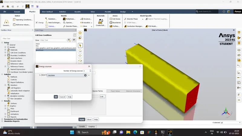
- ENERGY-SOURCE.
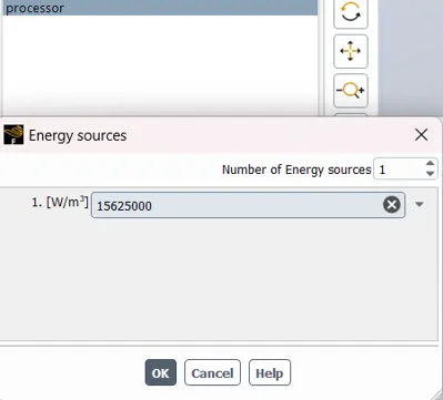
PROCESSOR is where all Heat is being Generated, So Energy Source term is added. Source term is considered as Heat Produced by Volume Of Processor
Graphic Card P = 1W.
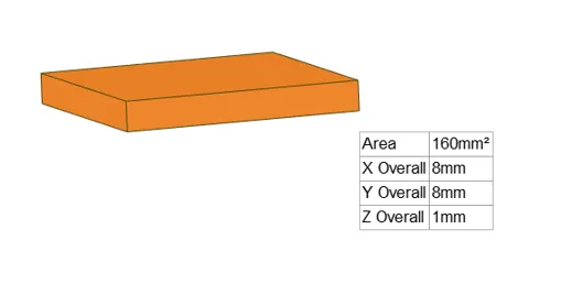
Volume Of Processor V = 8*8*1 mm = 6.4e-8`m^3`
ENERGY SOURCE - `P/V` = `15625000 W/m^3`
BASE-(STEEL)
| DENSITY | 8030 (kg/m^3) |
| Cp(SPECIFIC HEAT) | 381 (J/kg_k) |
| THERMAL CONDUCTIVITY | 16.27 (W/mk) |
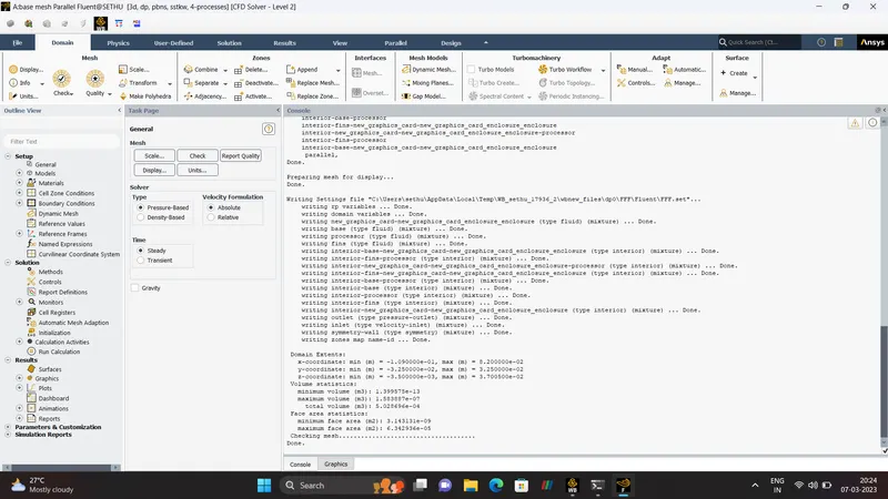
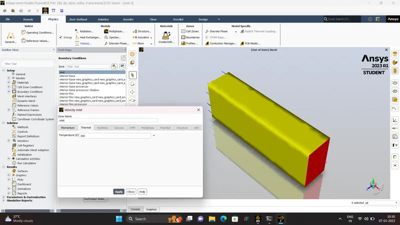
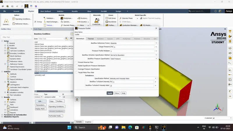
- HYBRID INITIALIZATION.
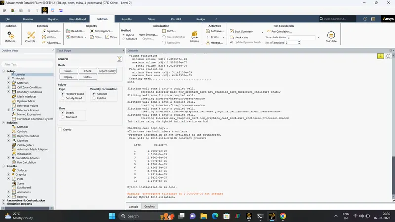
Hybrid Initialization defined as the Collection Of Recipes and Boundary Interpolation Method. It Solves the Laplace's Equation to determine the Velocity and Pressure field.
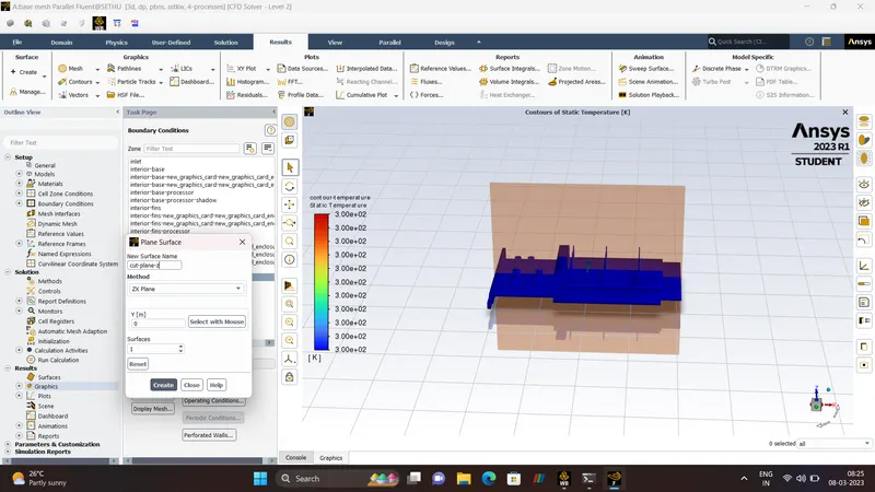
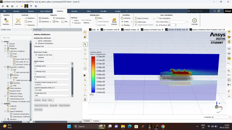
- Creating CUT_PLANE_Z.
- TEMPERATURE CONTOUR.
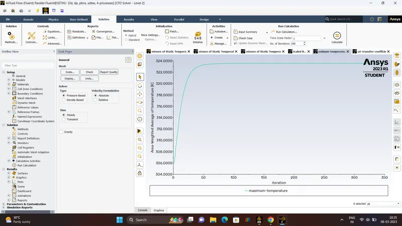
- MAXIMUM TEMPERATURE
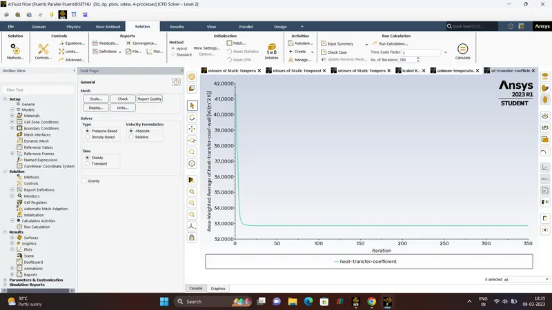
- HEAT_TRANSFER_COEFFICIENT.
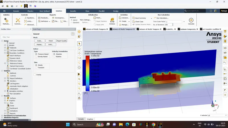
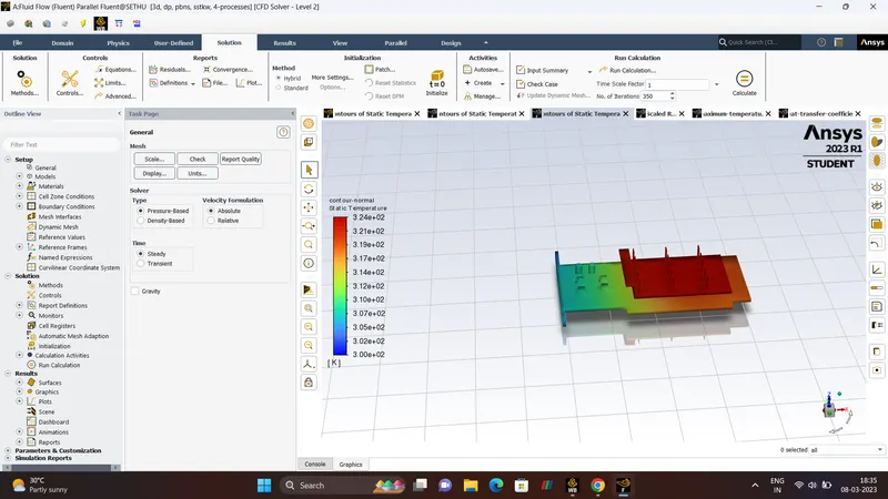
- SCALED RESIDUAL.
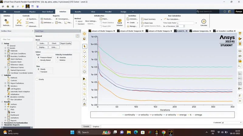
- TEMPERATURE
- HEAT_TRANSFER_COEFFICIENT.
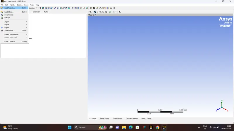
- POST-PROCESSING.
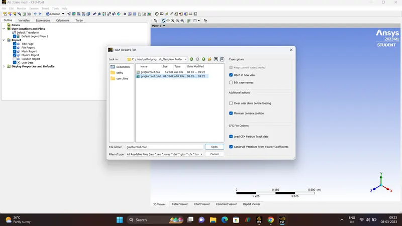
After completing the Setup/Solving Process final step is Post-Processing. In Post-Processing need to load data (CNTRL+L) which is been Write formatted into .CDAT file in the Solving Method.
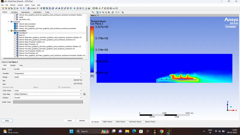
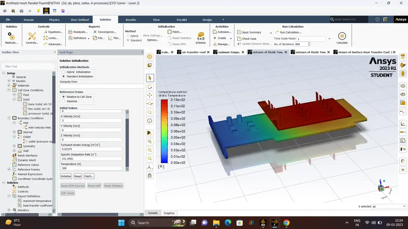
- TEMPERATURE.
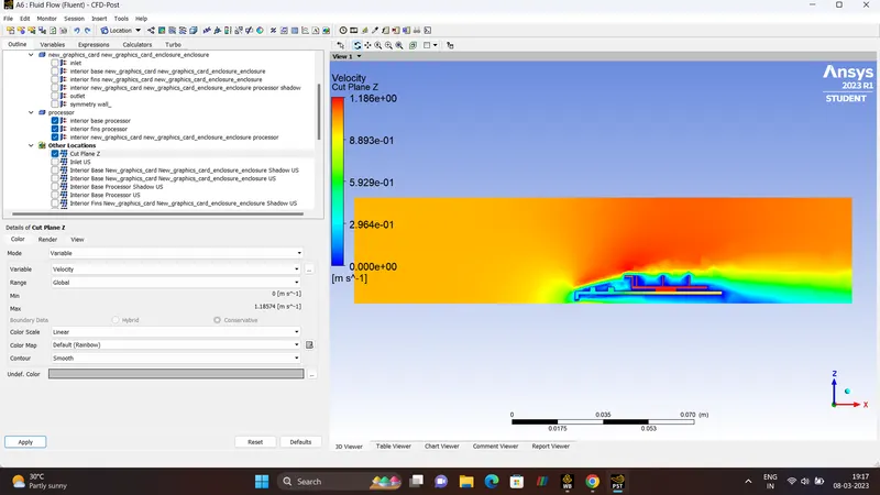
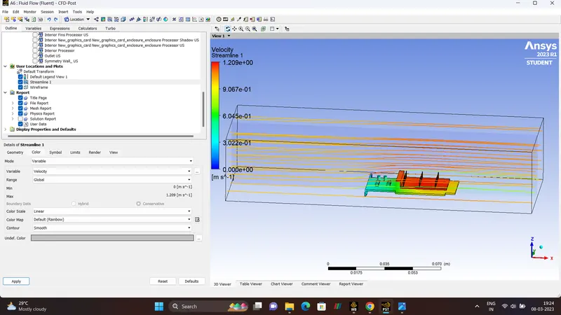
- VELOCITY.
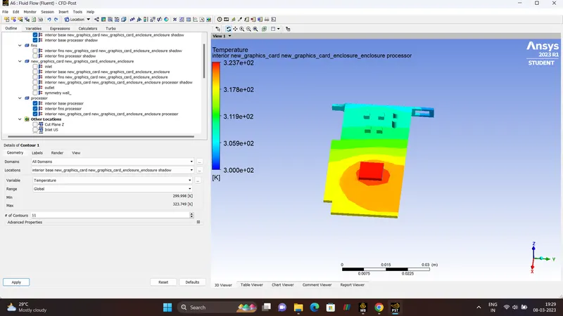
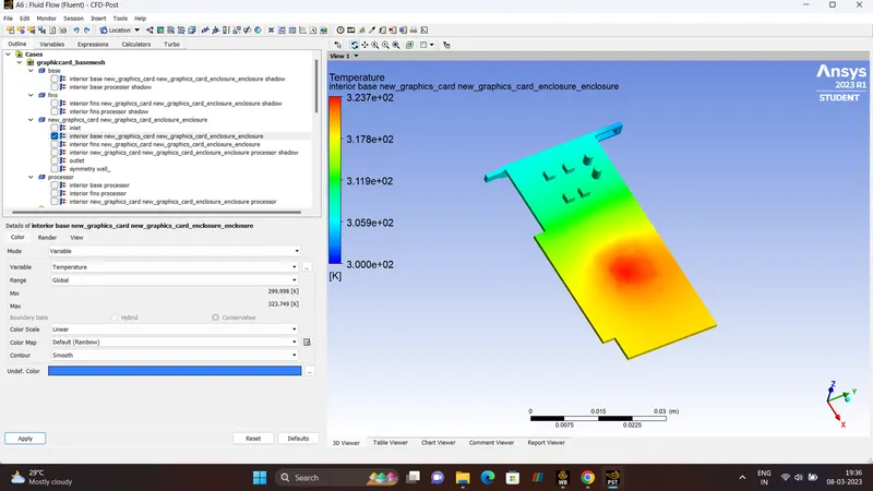
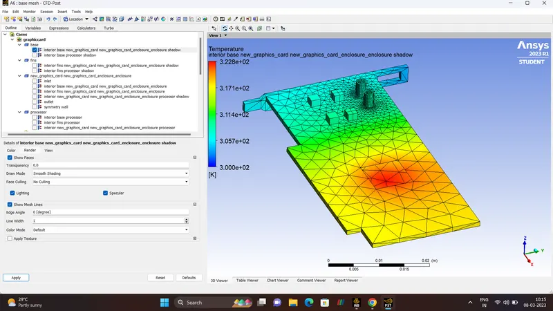
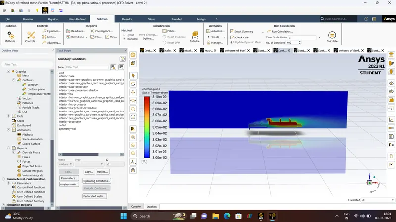
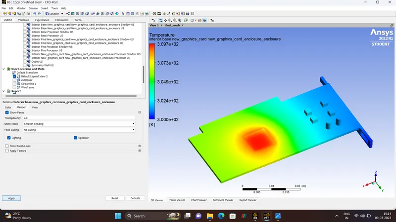
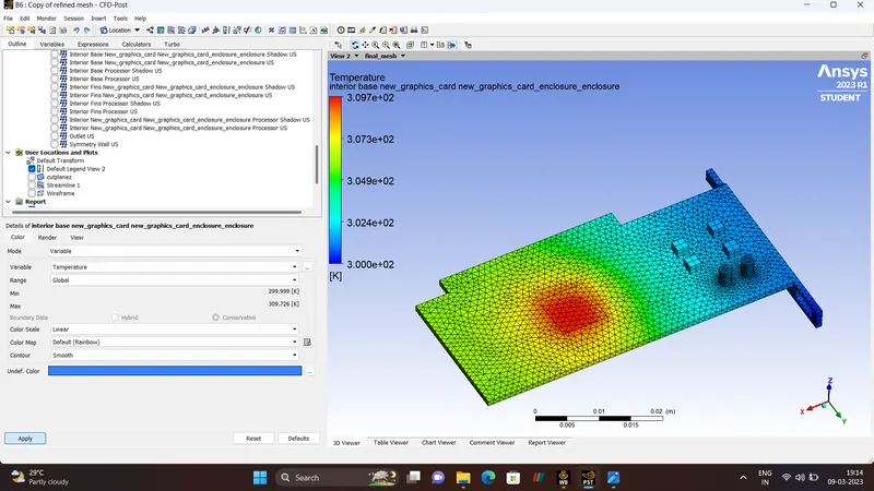
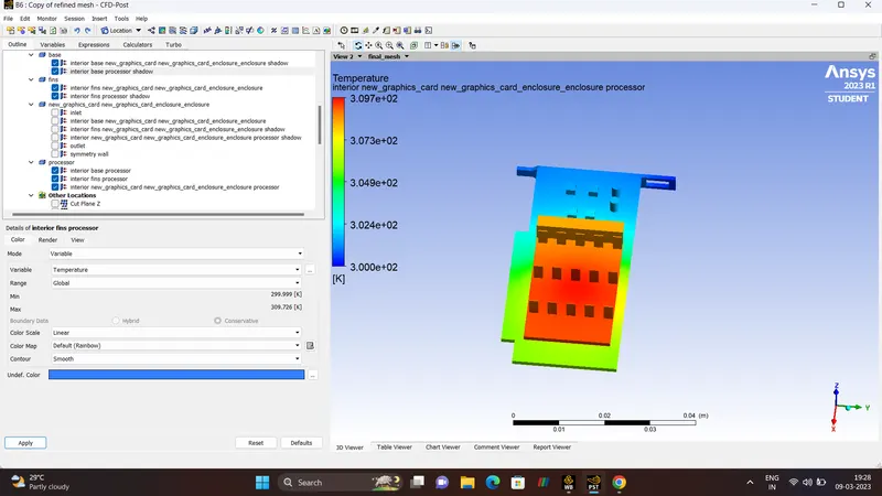
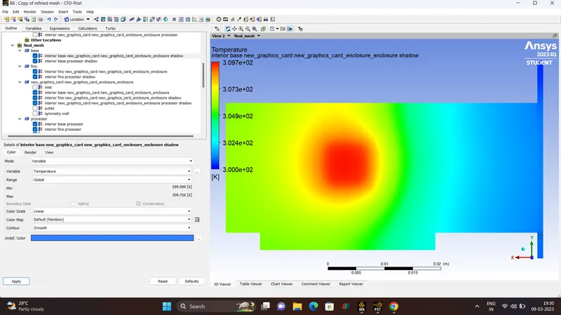
- TEMPERATURE POTENTIAL HOTSPOT.
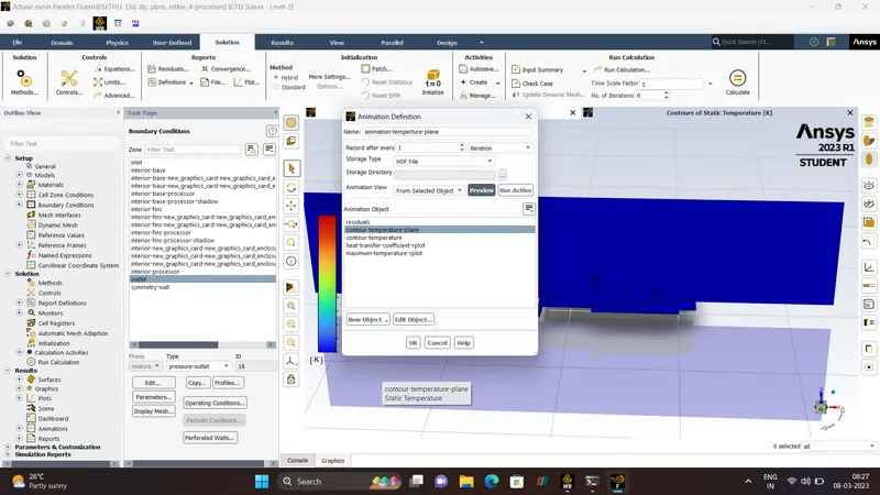
- ANIMATION.
TEMPERATURE
- CASE-1:
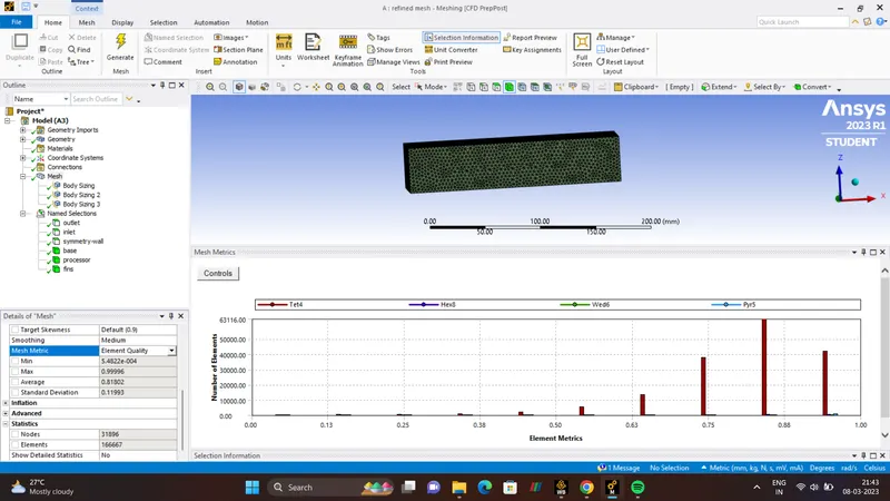
REFINED MESH
| ELEMENT SIZE | 3mm |
| FINS | 1mm |
| PROCESSOR | 1mm |
| BASE | 1mm |
| NUMBER OF NODES | 31896 |
| NUMBER OF ELEMENTS | 166667 |
| NUMBER OF ITERATIONS | 800 |
ANIMATION.
TEMPERATURE.
- RESIDUALS.
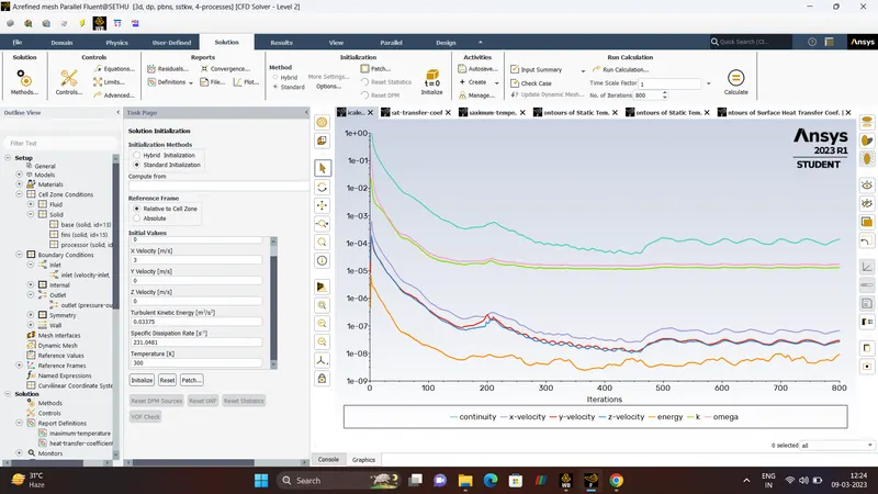
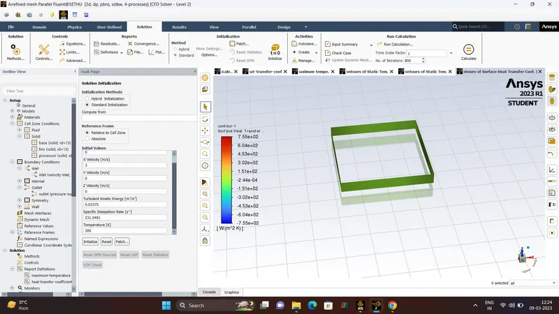
- HEAT-TRANSFER-COEFFICIENT.
- TEMPERATURE.

- CFD-POST-RESULTS.
TEMPERATURE.
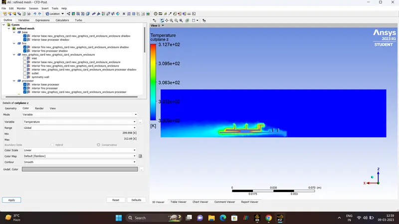
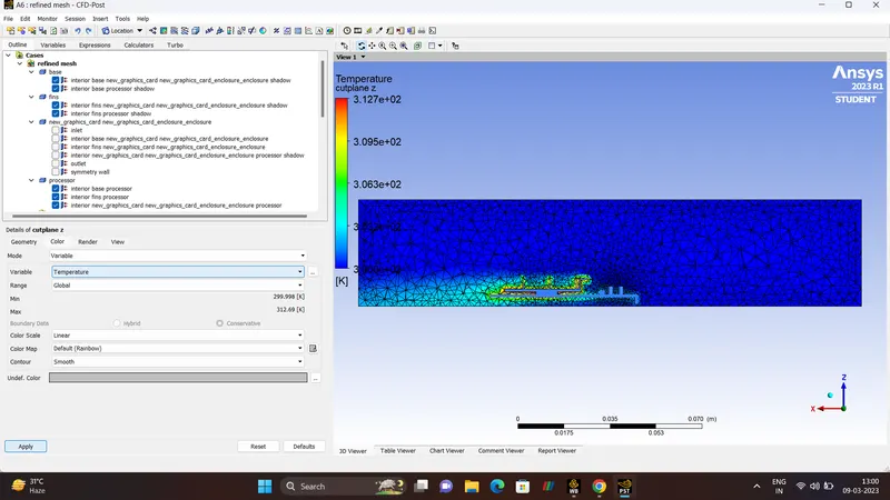
VELOCITY.
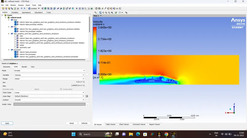
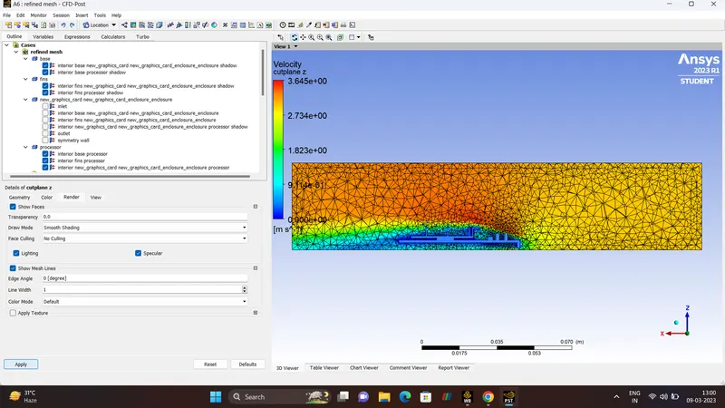
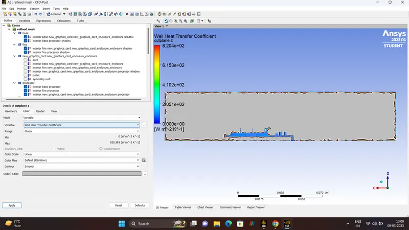
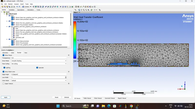
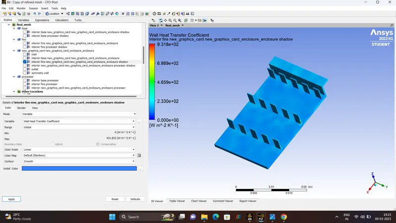
WALL-HEAT-TRANSFER-COEFFICIENT.
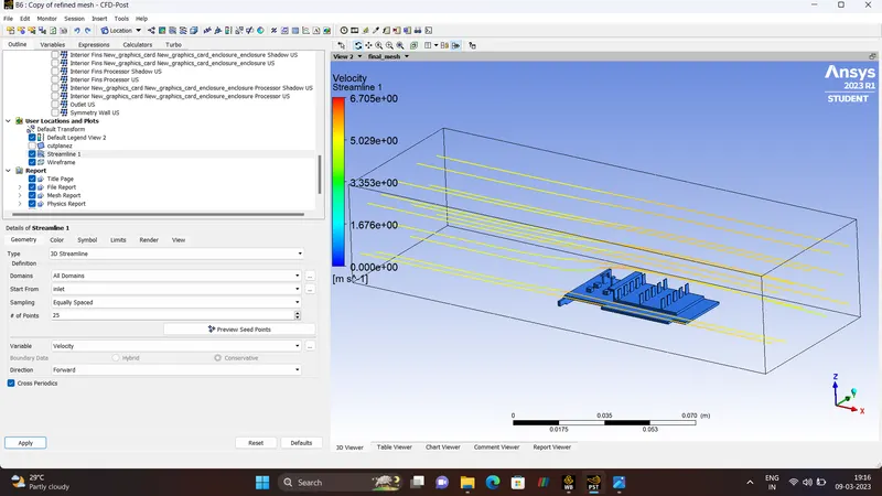
STREAMLINE-(TEMPERATURE & VELOCITY)
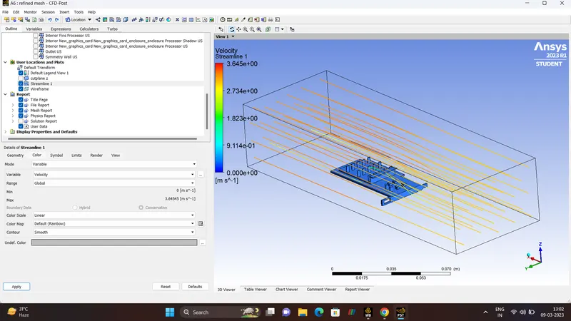
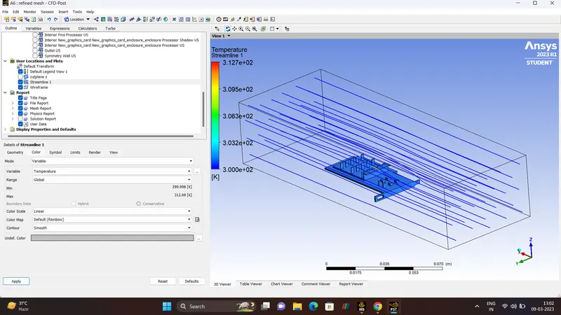
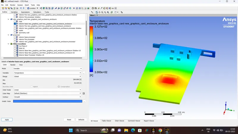
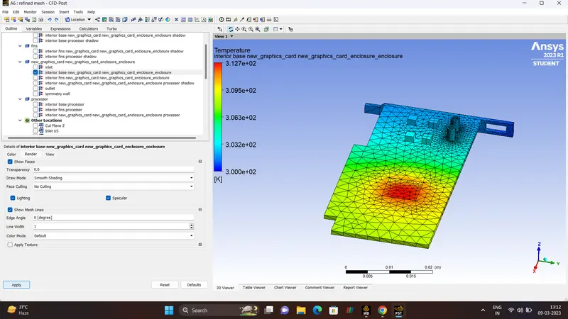
POTENTIAL-HOTSPOT (TEMPERATURE & HEAT TRANSFER COEFFICIENT)
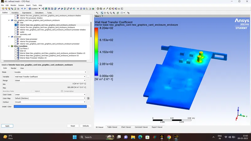
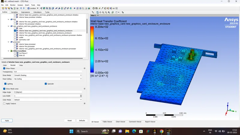
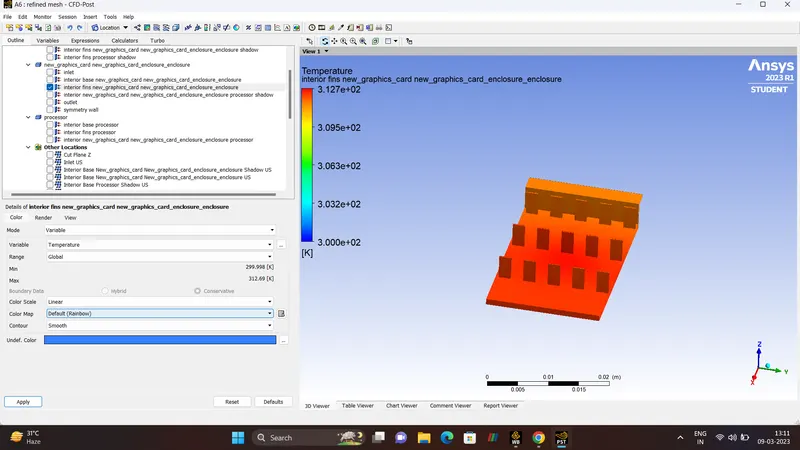
- CASE-2.
REFINED MESH
| MESH SIZE | 2.5 mm |
| FINS | 0.5 mm |
| PROCESSOR | 0.5 mm |
| BASE | 0.5 mm |
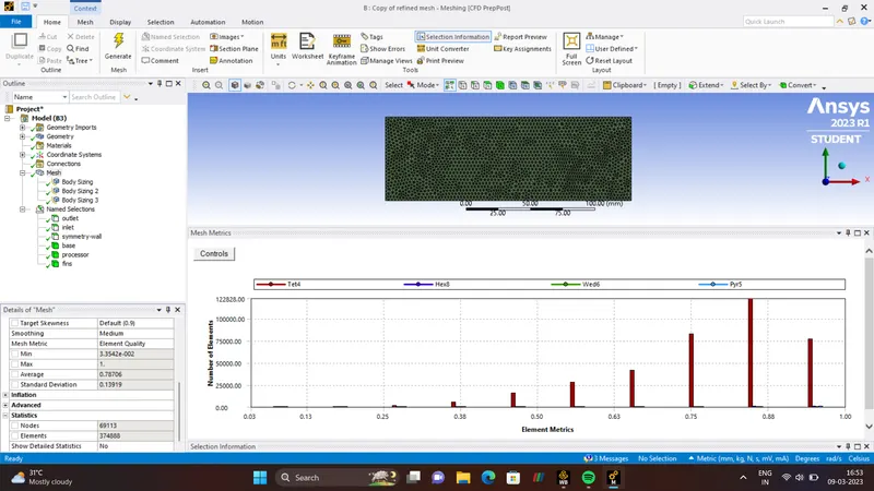
| NUMBER OF NODES | 69113 |
| NUMBER OF ELEMENTS | 374888 |
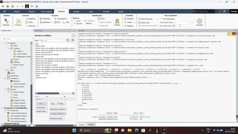
| NUMBER OF ITERATIONS | 400 |
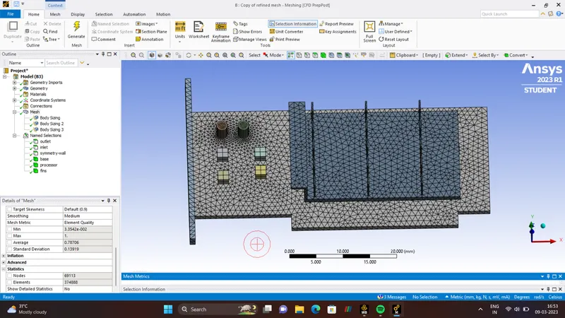
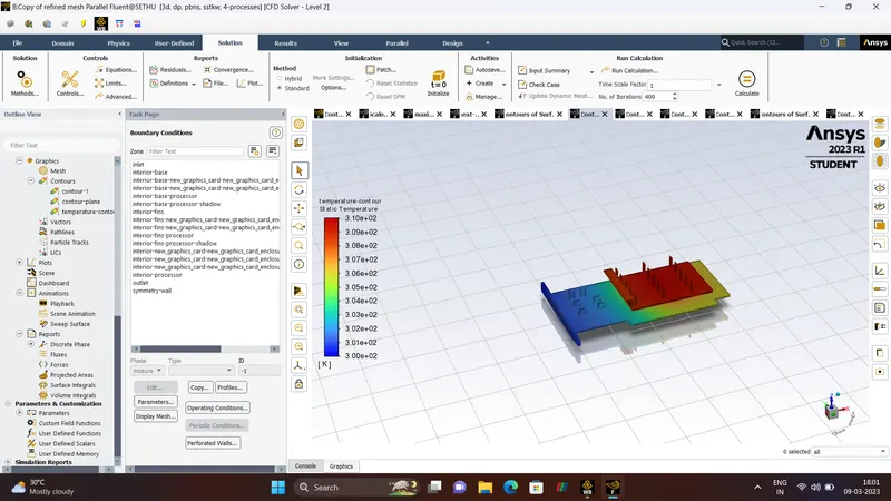
ANIMATION.
TEMPERATURE.
RESIDUALS.
TEMPERATURE
HEAT-TRANSFER-COEFFICIENT
- CFD-POST-RESULTS.
TEMPERATURE.
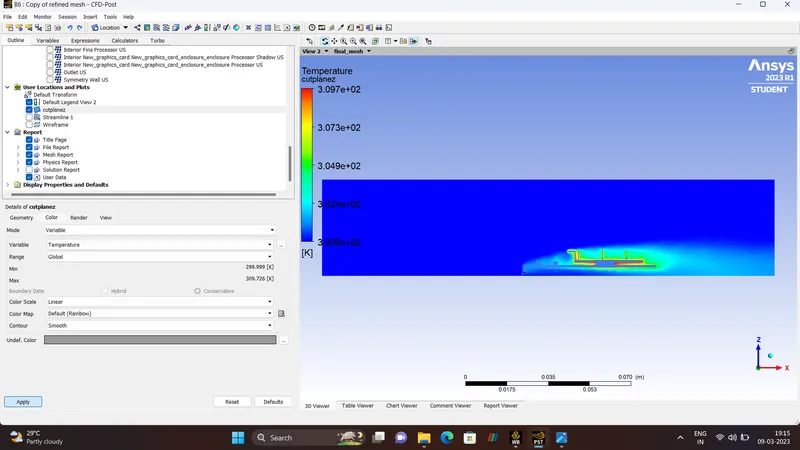
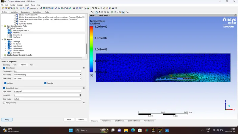
VELOCITY
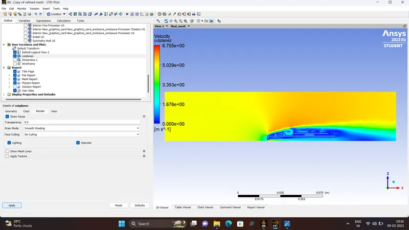
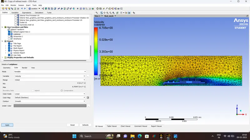
WALL-HEAT-TRANSFER-COEFFICIENT.
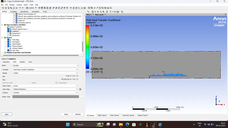
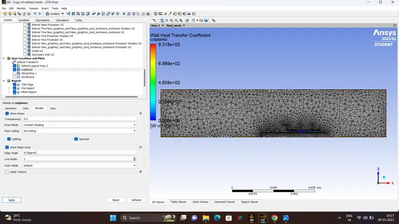
STREAMLINE-(TEMPERATURE & VELOCITY)
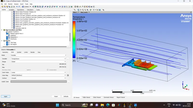
POTENTIAL HOTSPOT-(TEMPERATURE & HEAT TRANSFER CO-EFFICIENT).
ANALYTICAL SOLUTION.
- CALCULATION.
Length Of the Processor - 8mm - 0.008m
Width Of the Processor - 8mm - 0.008m
Height Of the Processor - 8mm - 0.008m
Aspect Ratio - H/L - 1/8 - 0.000125m
Characteristic Length = L*(2*((aspect_ratio)+1))^0.5
0.008*(2*(0.000125+1))^0.5
= 0.01131m
- REYNOLD's NUMBER.
The Reynold's Number (Re) is defined as the dimensionless number, named after the Osborne Reynold, Ratio of Interial Force to Viscous Force. The Reynold's number can be expressed in terms of
| `Re rarr (rho*v*L)/mu` |
`Re rarr Density.`
`v rarr velocity (m/s)`
`mu rarr kinematic viscosity m^2/s`
`L rarr Characteristic length m`
The Inlet Velocity to calculate the Reynold's number for three cases are Velocity v = 1, 3, 5 m/s.
CASE -1 :- INLET-VELOCITY `rarr`1
`Re rarr (1.225 *1*0.01131)/(1.7894e-05) rarr (0.01385475)/0.000017894 rarr 774.267`
CASE -2 :- INLET-VELOCITY `rarr 3`
`Re rarr (1.225*3*0.01131)/(1.7894e-05) rarr 2322.8`
CASE -3 :- INLET-VELOCITY `rarr 5`
`Re rarr (1.225 *5*0.01131)/(1.7894e-05) rarr 3872.20`
CONCLUSION.
- Steady_State Conjugate Heat Transfer analysis on a model of Graphic Card is Simulated using Ansys-Fluent.
- The Maximum Temperature for inlet velocity 1m/s is 323.5 k and for velocity 3m/s is 312.3 k and for final velocity 5m/s is 309.3k.
- We can clearly able to see that increase in velocities in each simulations there is an decrease in temperatures.
- Potential Hotspot is identified on a model of Graphic Card.
- Finally Grid Independence test is Done for Graphic card model.