Week 5 Challenge : Surface wrap on Automotive Assembly
AIM:-
- To study and Perform a Surface Wrap on a Automotive Assembly Using Ansa.
OBJECTIVE:-
- To Check the geometrical Errors and to delete the unwanted Surfaces to perform a Surface Wrap with the Target length Of 3mm.
INTRODUCTION:-
In this Project, Surface Wraping is done for FORD ENGINE with DOHC Type.
FORD ENGINE.
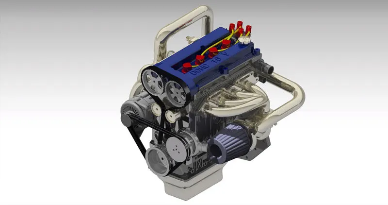
Ford Motor Company ( Ford) is an American multinational automobile manufacturer headquartered in Dearborn, Michigan, United States. It was founded by Henry Ford and incorporated on June 16, 1903. The company sells automobiles and commercial vehicles under the Ford brand, and luxury cars under its Lincoln luxury brand.
DOUBLE OVER HEAD CAMSHAFT ( DOHC)
- In Double OverHead CamShaft, two camshaft arrangement is made in which One regulates the Inlet Valves and Other regulates the Exhaust Valve.
- Due to this, the Interia Force created in the Valve train is reduced. this restricts the air flow at the higher engine speed. In this type of arrangement, Spark Plug is placed in the Optimum Place which improves the Combustion Efficiency.
ENGINE.
Heat Engine is a device which Operates by Conversion of the Chemical Energy into the Mechanical Energy which is used to do a Mechanical Work. Heat Engines are Classified into Two types.
- INTERNAL COMBUSTION ENGINE (IC).
- EXTERNAL COMBUSTION ENGINE (EC).
INTERNAL COMBUSTION ENGINE (IC).
- The combustion of fuel takes place inside the Engine Cylinder and Produces High Thermal Energy.
Eg: Petrol, Disel Engines.
EXTERNAL COMBUSTION ENGINE (EC).
- The Combustion of fuel takes place Outside the engine and transfers the Heat buy a medium to Operate the Cylinder.
Eg. Steam Engine.
COMPONENTS OF IC ENGINES.
To Operate the I.C Engines many Components have to Function.
- Cylinder.
- Cylinder Head.
- Piston
- Piston Rings
- CombustionChamber
- Intake & Exhaust Manifolds.
- Inlet & Exhaust Valves.
- Spark Plug / Fuel Injector.
- Connecting Rod.
- Crank & Crank Shaft.
- Gudgeon Pin.
- Crank Pin.
- Cam Shaft.
- Cams.
- Crank Case.
- FlyWheel.
GEAR BOX
A Gear Box is defined as Mechanical Device that Transmits power from a Source, such as Engine, to a Machine or Vehicles. It uses Gears and Gear Trains to provide Speed and Torque Conversion from a Rotating Power Source to another Device. Gears can be Engaged and Dis-engaged to change the Speed and Torque of the Output-Shaft, this process is Known as Shifting Gears. Gear Boxes are used in a wide variety of applications, including Automobiles, Bicycle, Motorcycles and industrial machinery. They are commonly found in Manual and Automatic Transmission's of Vehicle. The Gear Box also helps to maintain the Engine's Speed Optimal RPM range for a given Speed and Load.
PARTS OF GEAR BOX
Gear Box consists of following main parts and they are,
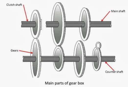
1. CLUTCH SHAFT
2. COUNTER SHAFT
3. MAIN SHAFT
4. BEARINGS
5. GEARS
- CLUTCH SHAFT.
A Clutch Shaft is also known as a Driving Shaft, Which utilizes the Force form the Engine and supplies it to the other parts. The Driving is attached via Clutch and when the clutch is engaged the Driving Shaft starts to Rotate. The Clutch gear is provided with a Single Gear fixed on it and it rotates with the Engine Speed same as the Crankshaft. Both the Driving and main Shaft are in same line.
- COUNTER SHAFT.
The Counter Shaft is larger as compared to the rest of the three GearBoxes. It is provided with numerous Gears in variant sizes which can produce a broad level of Torque. It rotation is different but contributes consecutive Speed just like Clutch Shaft.
- MAIN SHAFT.
Output Shaft is also known as Main Shaft. It revolves at a different Speed and also gives the mandatory torque to the vehicles. Main Shaft is splined so gears could move both Engage and Disengage in better way. The netural gear is the standpoint in which no Gear is Engaged with Counter-Shaft.
- BEARINGS.
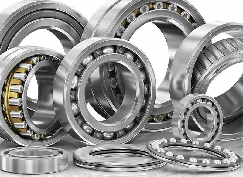
Bearings is elevated on both ends of every Shafts. They serve two purposes,
1. It promotes Support.
2. Delivers Maximum Power with less Frictional losses.
- GEARS.

Gears is used to transport power from One Shaft to another Shaft. The Quantity of Torque Transported via Gears depends on number of Teeth and Size of Gears. The Higher Gear Ratio Produces Higher acceleration, and minor the Speed. All Gears are Stabilized except the Main Shaft Ones, they can skid into either direction along the Shafts. If the ratio of Gear is higher than 1, the car will maintain a Higher Acceleration and will travel at a Higher Speed.
TRANSMISSION.
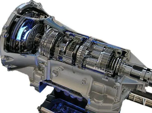
A Transmission is a Mechanical Device which Uses Gears to Change the Speed or Direction Of a Rotation in a machine. Many Transmission have Multiple gear ratio but there also transmission which uses single fixed Gear ratio.
There are many types of Transmisson.
- Automatic Transmission.
- Manual Transmisson.
- Continous Variable Transmission.
- ANSA.
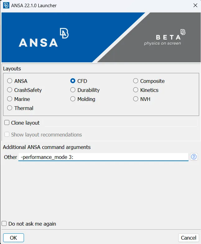
Automatic Net Generation for Structural Analysis.
ANSA is a Computer Aided-Engineering tool for Finite Element Analysis and Computational Fluid Dynamic Analysis widely used in the Automotive Industries. It is developed by BETA CAE Systems. ANSA tools are mainly used in Automotive Industries to mesh Plastic/Sheet metal components for CFD analysis. Tool is used for Topology Cleanup, Meshing, Improving Mesh, Assigning Thickness and Preparing Solver Deck.
- GEOMETRY.
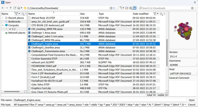
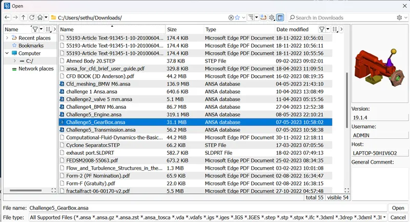
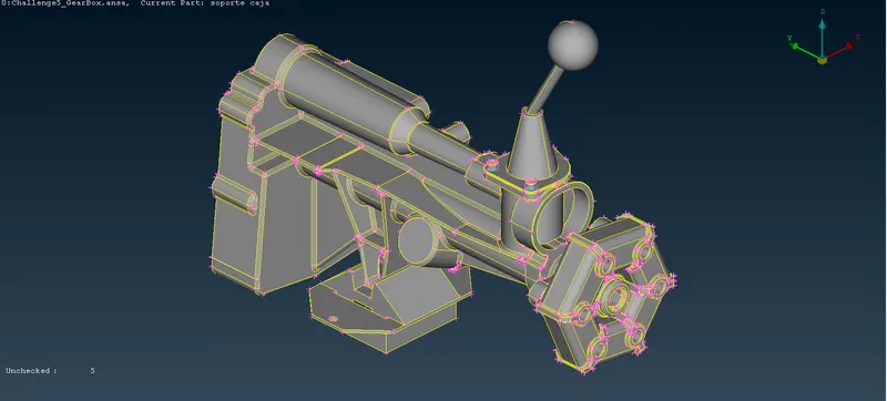
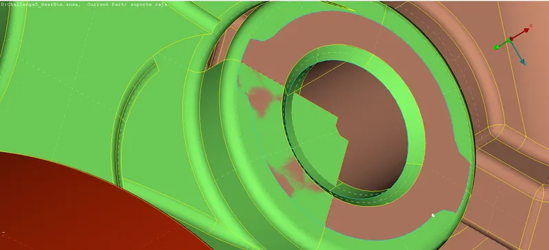
To do a Surface Warp in a Automotive Assembly in Ansa Software, First Step is to Import a CAD Model of a GEARBOX, ENGINE, TRANSMISSION,in the Ansa Spaceclaim. Once the CAD model is Imported in Ansa we need to Check the Unwanted Surface which will be Presented With the CAD model like Glitching, Ring Shape Surfaces, overlapping Surface..etc, need to delete those Surfaces with the Help of Universal Delete Option in Order to do a SURFACE WARP.
- 1. ENGINE MODEL.
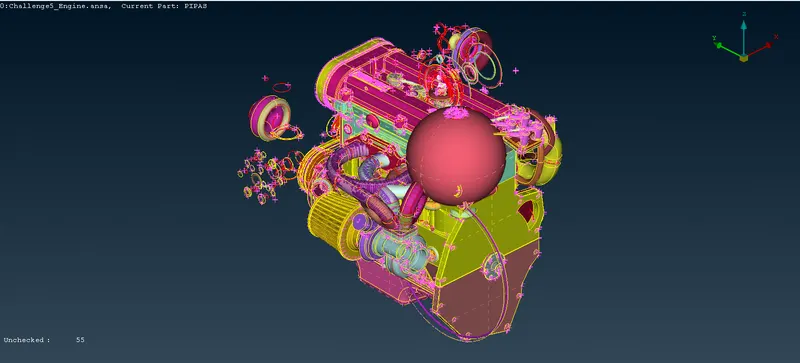
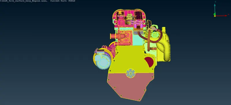
We Can able to see the Unwanted Surface like Big ball Shaped Surfaces, Outer Rings etc, in this CAD model Of ENGINE. Our main Outcome is to delete those Surfaces, because these Surfaces are not required for SURFACE WARPPING Process. Some of the deleting methods shown below.
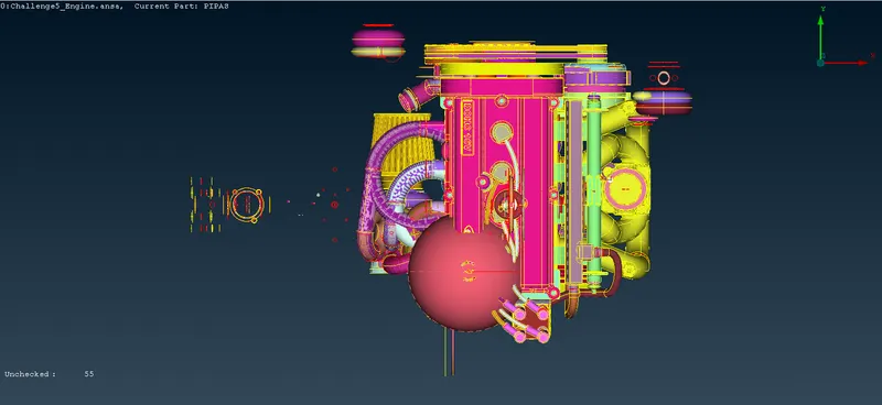
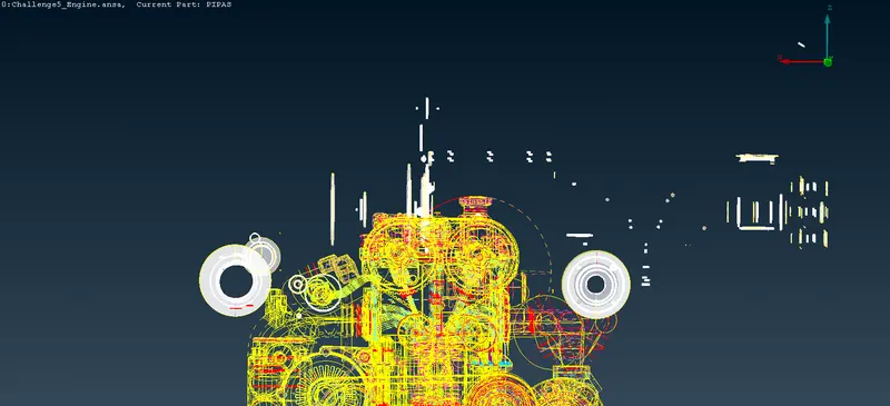
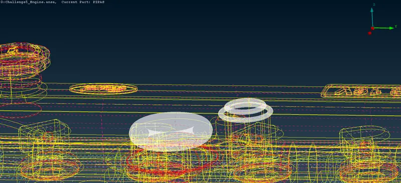
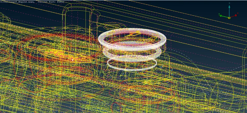
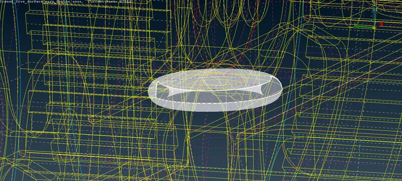
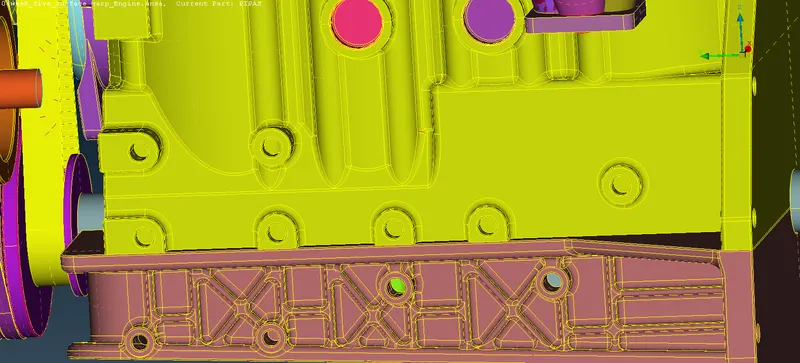
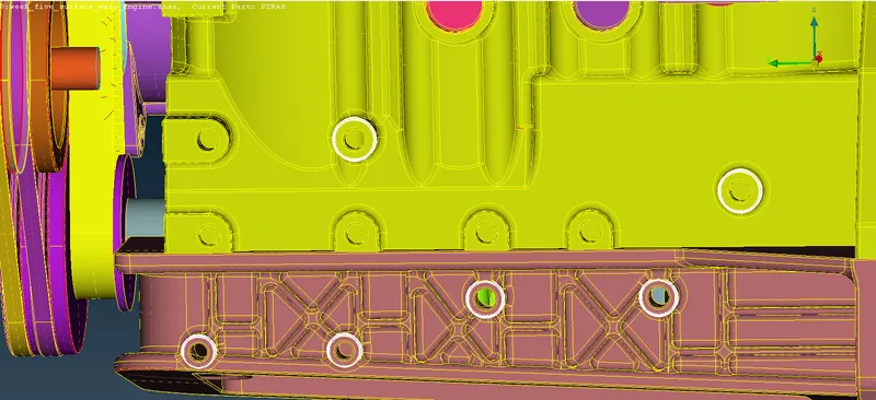
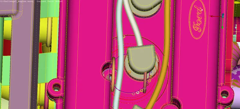
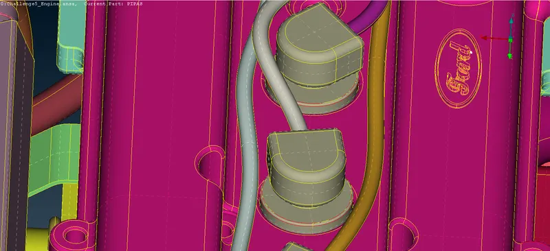
From the above Images we can come to conclude that by deleting One by One, it takes more Time to do, So One of the Best Option is to Use NOT command. In Such a way with the help of NOT option we can Isolate the Engine Components and lets delete the Unwanted Surfaces.
- UNWANTED SURFACES.

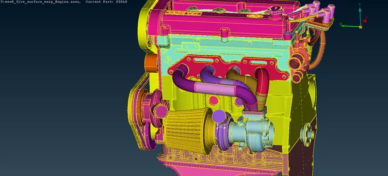
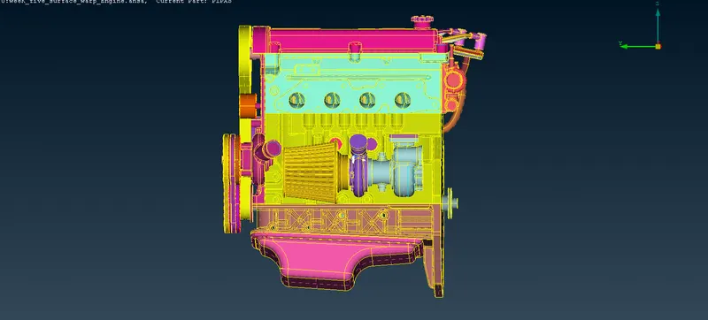
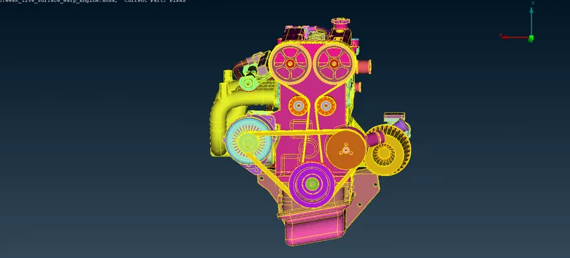
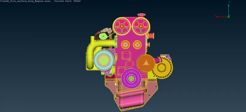
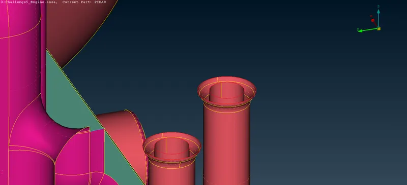
After Deleting those Surfaces Still we need to delete the Glitching surfaces and we dont need those EXHAUST MANIFOLD PIPES, ROTATING BELTS.
BEFORE AFTER
- PATCH
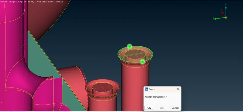
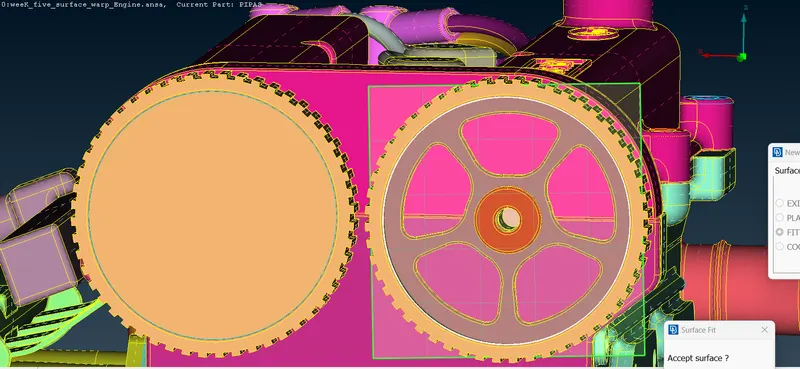
After doing Topo Clean-up, Now Patching needed to done so that Surface Wrap will be neater.
BEFORE AFTER
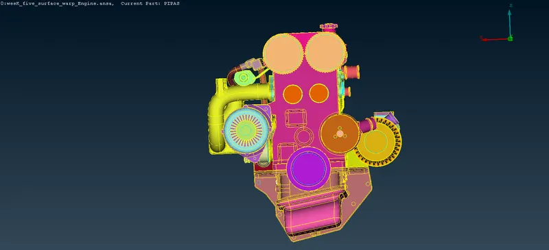
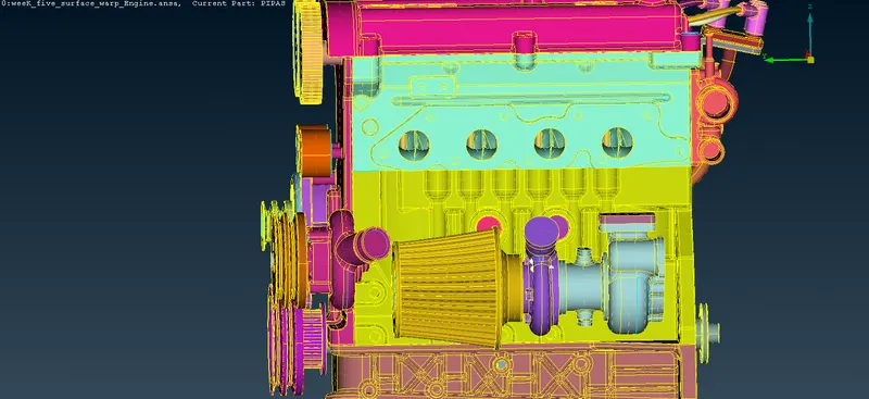
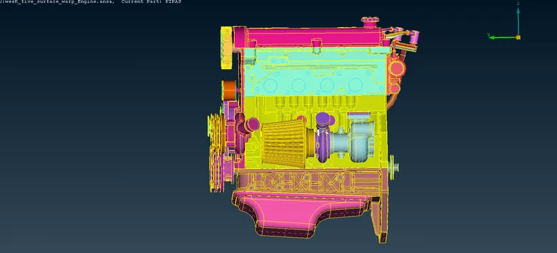
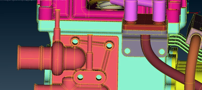
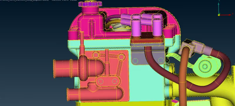
- FINAL OUTPUT.
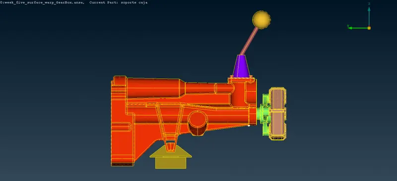
- 2. GEAR BOX.
ENTITIE MODE.
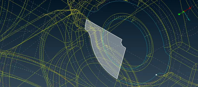
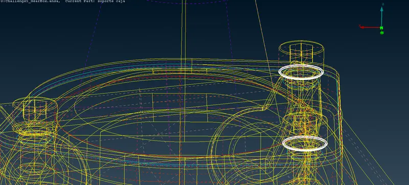
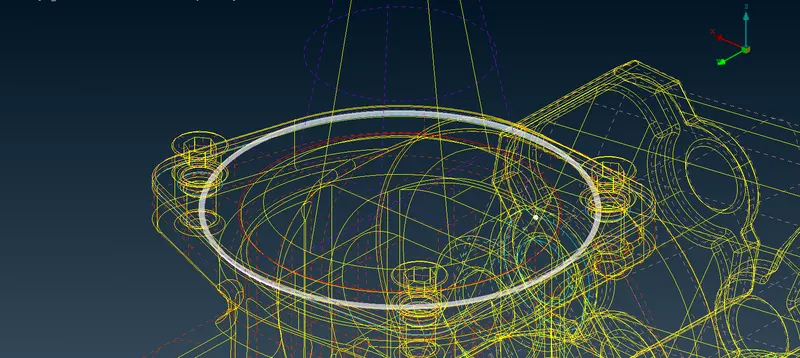
DELETING SURFACES.
PATCH.
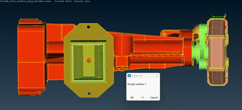
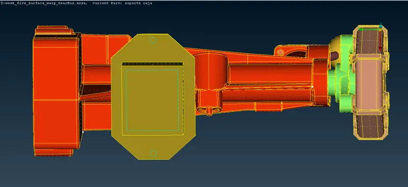
- FINAL OUTPUT.
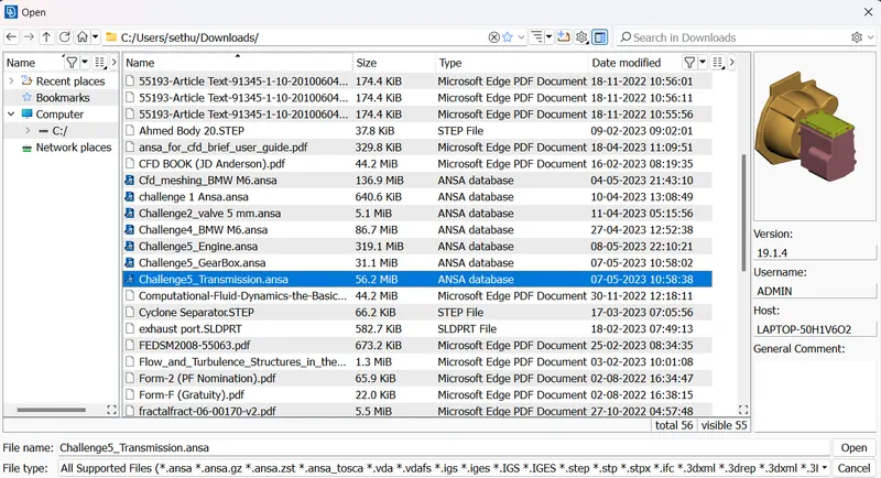
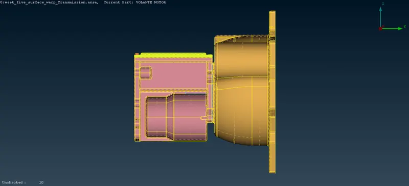
- 3.TRANSIMISSON.
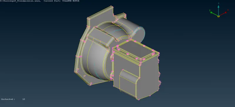
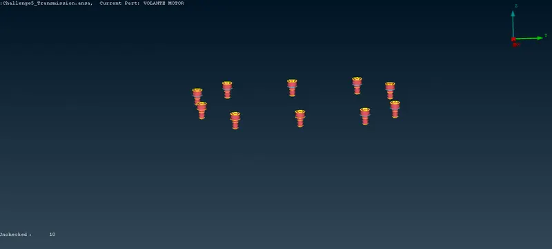
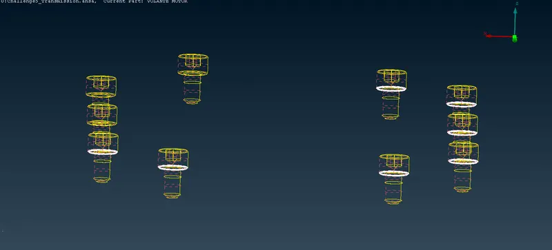
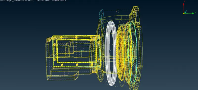
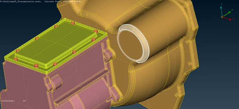
FINAL OUTPUT.
- SURFACE WRAP.
Surface Wrap is defined as the wrapper which wraps the respective geometry of interset to create a Single Volume which does not have the Non-intersecting Surfaces, manifolds edges. Surface warpping can be done both Internal and External Ways. In Our Project External Wrapping is Done.
- MERGING.
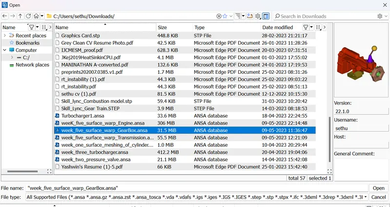
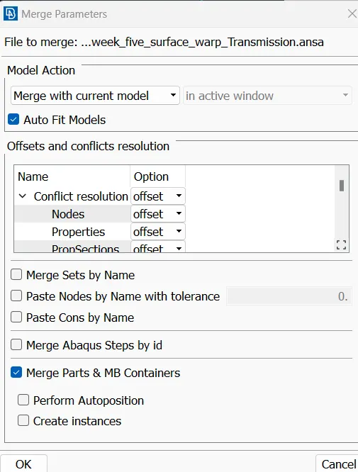
When all three Models of ENGINE, TRANSMISSION, GEARBOX Topo-Cleanup is done by clearing the Geometrical errors, Now next Step is to do Merging Process for all three Components one by one.
FILE`rarr` MERGE`rarr` FILE LOCATION`rarr` AUTOFITMODEL /MERGE PARTS and MB CONTAINERS`rarr` Click OK
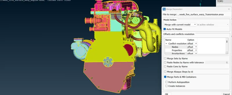
MERGE OUTPUT.
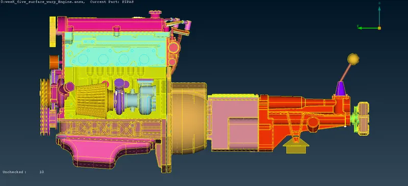
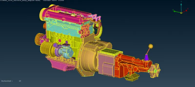
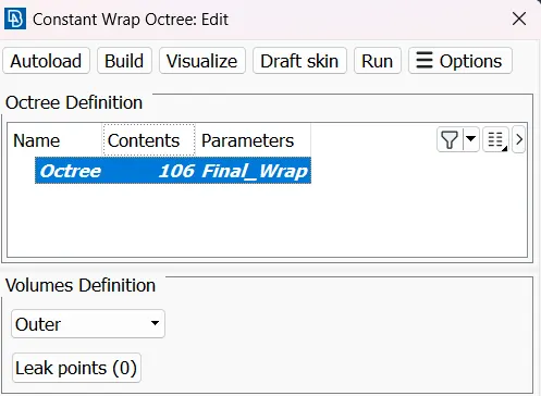
Before Moving into the Surface Wrap we need to delete the unwanted PIDS in the properties manager. The left side of the first images shows as we have total of 1594 PIDs in that many PIDs need to be deleted. Finally with the Compress Option we can come to conclude that 106 PIDs is been Present.
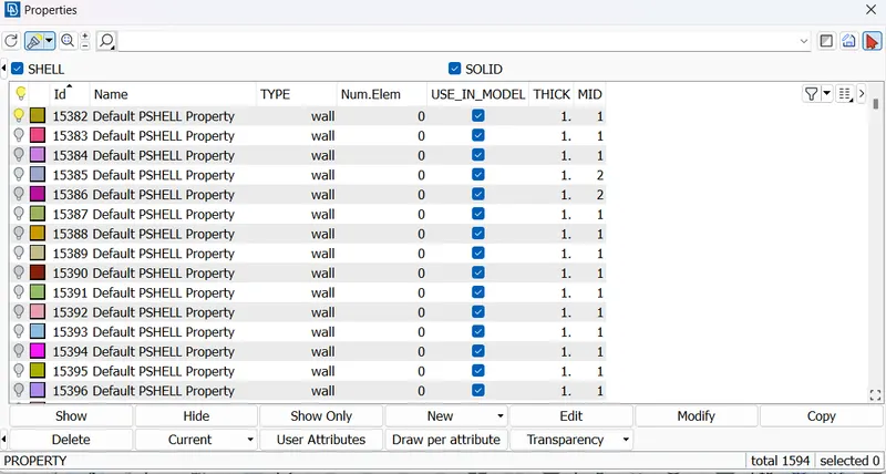
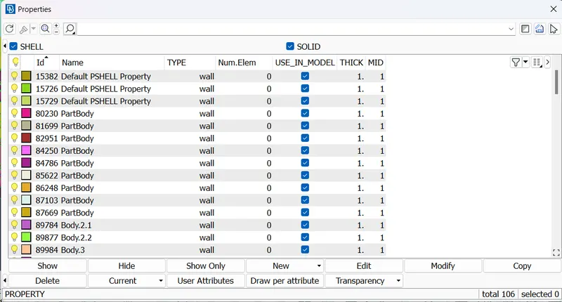
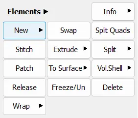
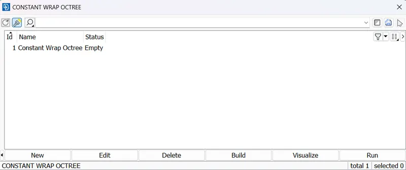
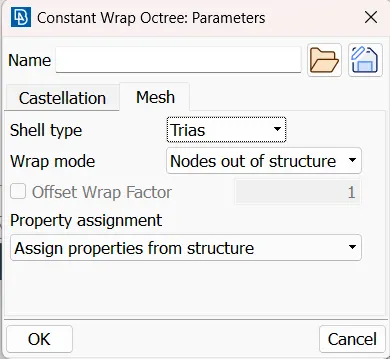
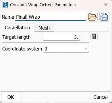
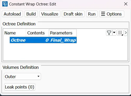
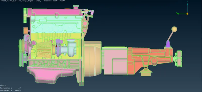
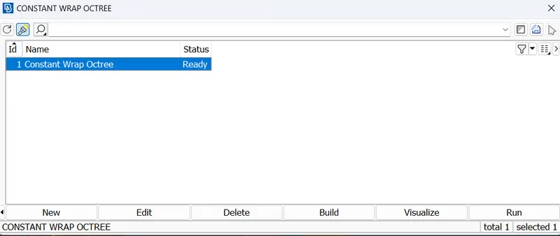
To do Surface Wrap which is present under the ELEMENT section,Wrap. There are Two types of Wraps, they are CONSTANT WRAP and VARIABLE WRAP. We are going to use CONSTANT WRAP,by clicking the Constant Wrap an dialogue box will be pop-up in that we need to click the EMPTY, then we need to Asign the TARGET LENGTH as 3mm and Name it has FINAL_WRAP.
- RESULTS.
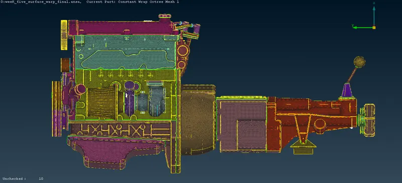
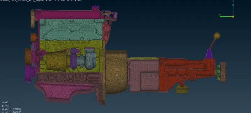
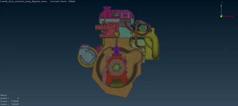
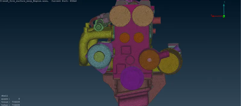
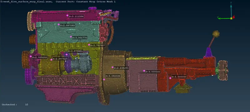
When We cut the Surface into the Half we can able to see the Surface Wrap has done perfectly has a result it shows a Single Volume.
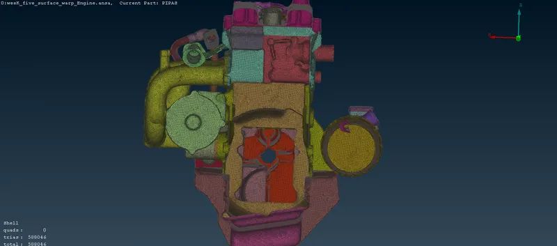
- TARGET LENGTH - 3mm
https://drive.google.com/file/d/12pdiTAKjozDAgByChVcwjD---515I1a4/view?usp=share_link
- CONCLUSION.
Hence we can Come to conclude that in this project Surface Wrapping is done with target lenght of 3mm and the results are Satisfied.