Week 9 Machining with Planer Challenge
Objective : To setup the simulation of the given machining with planer model setup to obtain the desired results.
Setting up the simulation
To set up the simulation, first we need to import all the required material cards such as Structural Steel and AL 1100-O for the workpiece
The below materials can be found in the General materials library.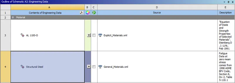
Importing geometry :
Next we import the geometry and rename them as workpiece and cutting_tool
Material definition :
Cutting_tool : Structural Steel
Workpiece : AL 1100-O
Then we will open Ansys explicit dynamics to set up the rest of the simulation.
Body interactions : We create a body interactions collector with all bodies in the set-up.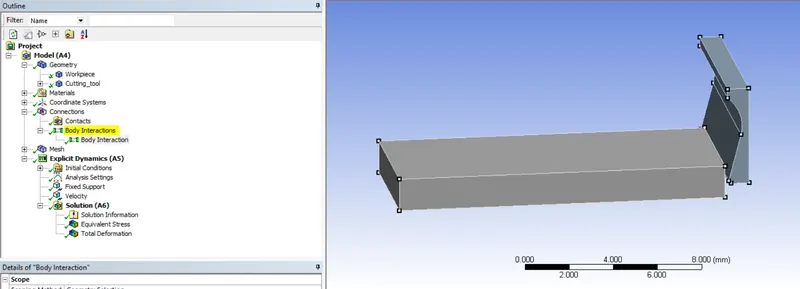
Mesh : Next we mesh the components.
Patch conforming method of tetrahedrons is applied on cutting_tool.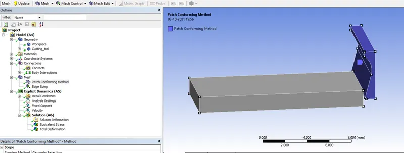
Next sizing is applied along the 4 edges of the work-piece of 10 elements per edge, as is shown below.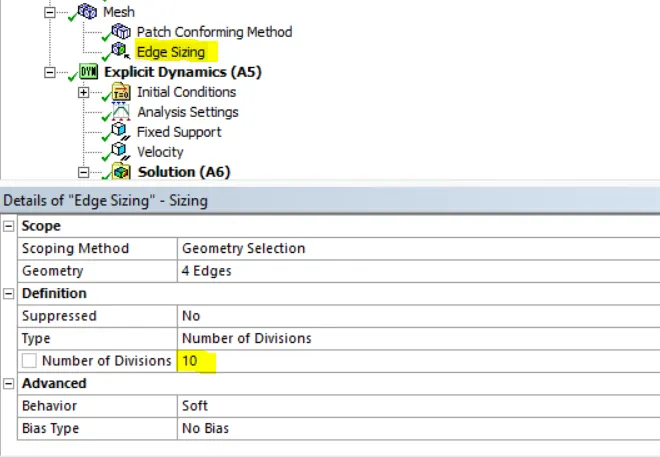
The mesh looks as shown below.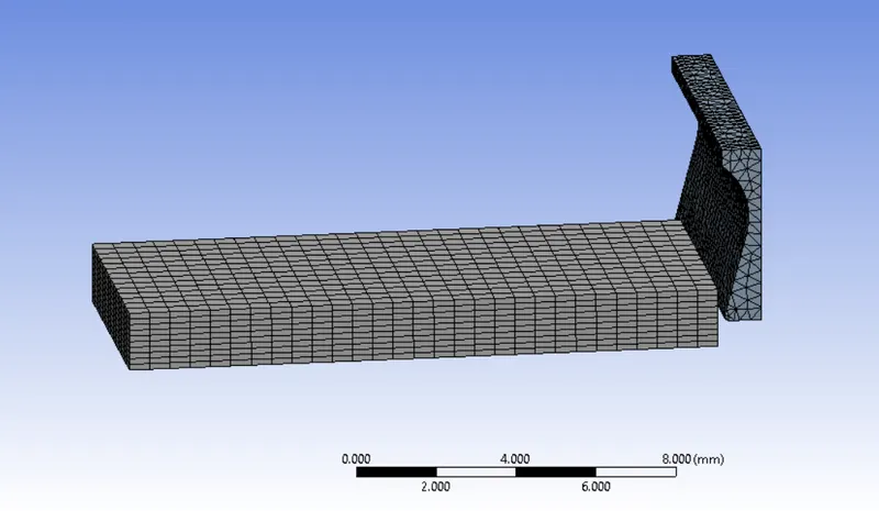
Analysis Settings :
Next we go to analysis settings to set up the kinematics of the simulation
The analysis is run for an end time 7.5e-4 and the rest of the analysis conditions are kept as default.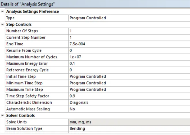
NOTE : For case 2 an end time of 0.001s is chosen depending on cutting speed.
Fixed Support : Next a fixed support is applied at the bottom face of the workpiece.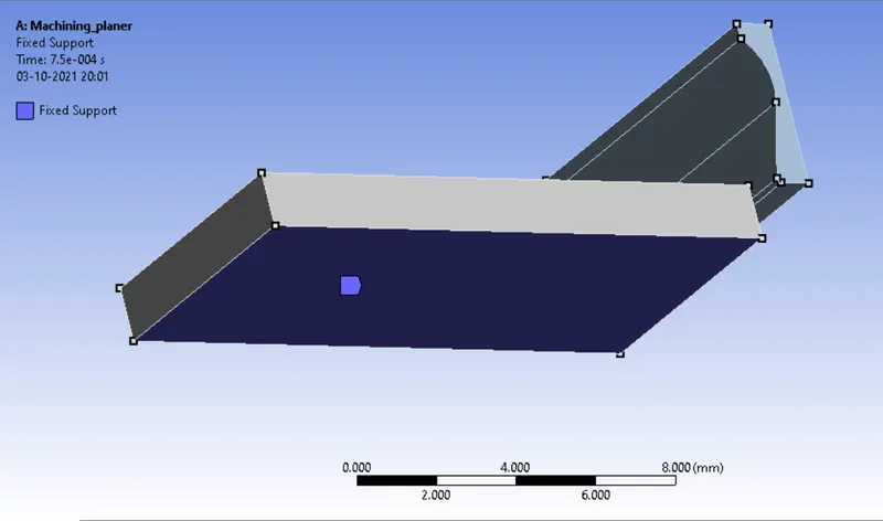
Velocity : A velocity is then applied on the cutting tool in the tabular form as shown of 20000 mm/s.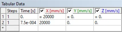
Output Parameters : The following parameters are selected for output from the simulation.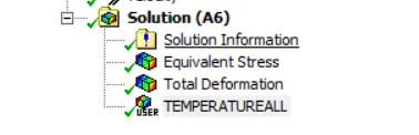
The equivalent stress, total deformation and temperature are selected as output parameters.
The simulation is run on 2 cases, which are as discussed below:
Case_1 : Cutting_tool with a velocity of 20000 mm/s
Case_2 : Cutting_tool with a velocity of 15000 mm/s
Running the simulation :
Next we run the simulation. The simulation takes about 28 minutes to run as we can see from the runtime below.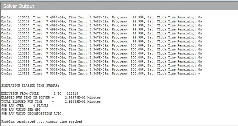
Post-processing :
Total Deformation :
Case 1)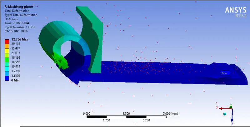
A total deformation of 32.756 mm occurs in the work piece.
Case 2)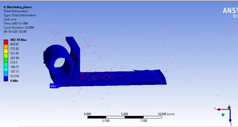
A total deformation of 32.756 mm occurs in the work piece.
Equivalent Stress :
Case 1)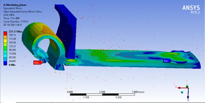
A maximum stress of 221.77 Mpa occurs in the work piece.
Case 2)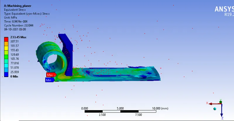
A maximum stress of 233.45 Mpa occurs in the work piece.
Temperature (user defined) :
Case 1)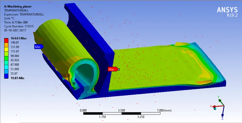
A peak temperature of 164.03 degree celcius occurs in the work piece.
Case 2)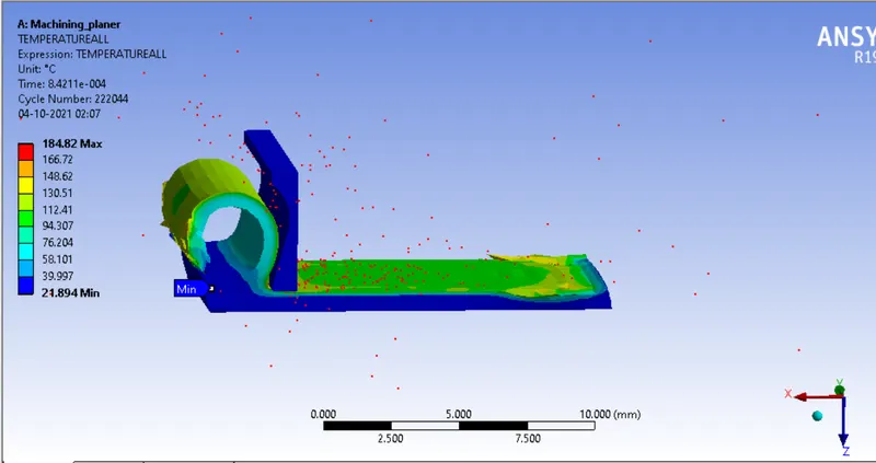
A peak temperature of 184.82 degree celcius occurs in the work piece.
Conclusion :
Hence the simulations have been run as per the desired criteria and the results have been obtained.
A higher temperature and stresses occur in the work piece in case 2 when the cutting tool velocity is lesser.
Result : File cannot be attached. Attaching google drive link.
Case_1
Case_2