Week 7-Long Piston With Cam
Objective : To perform the simulation of the buckle clip to study the stresses, strains and other requested parameters as per the criteria.
Procedure :
Setting up the simulation
To set up the simulation, first we need to import all the required material cards such as Structural Steel
The below materials can be found in the General materials library.
Importing geometry :
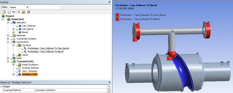
Next we import the geometry of the Cam_follower, Cam_barrel and Barrel and rename the components as shown below.
Material defintion :
The components are assigned Structural Steel. The Cam_Barrel and Barrel are given rigid definition so that we do not generate meshes on these components. The stresses and strainson the cam_follower are studied.
The contacts are assigned as frictionless and their are 2 contacts.
1.Between cam follower and cam barrel
2.Between cam follower and barrel
Setting up of joints :
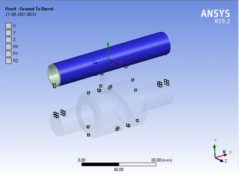
Fixed - Ground to Barrel
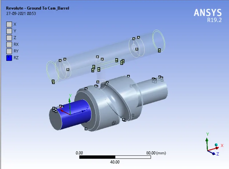
Revolute - Ground to Cam_Barrel
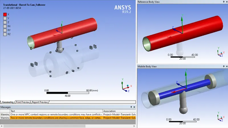
Translational-Barrel to Cam_follower
Meshing:
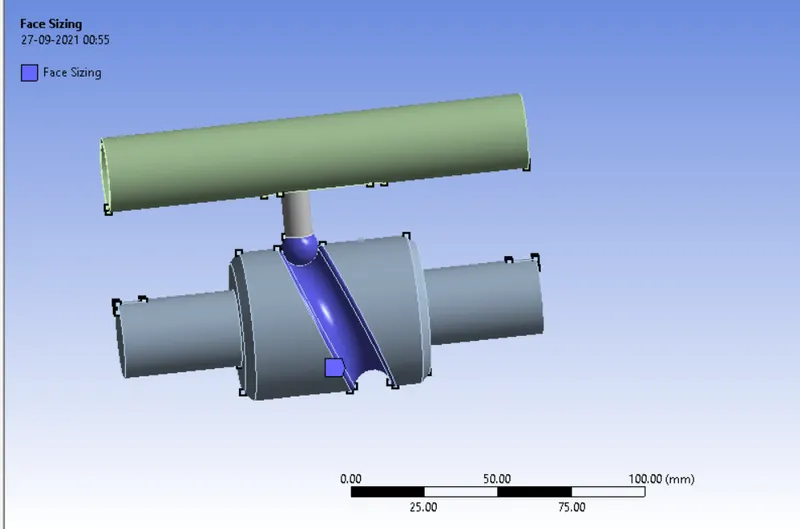
A face sizing of 3mm is applied on the cam_barrel groove and follower.
Setting up of joint-load :
A rotation of revolute joint is provided in angular increments as shown below.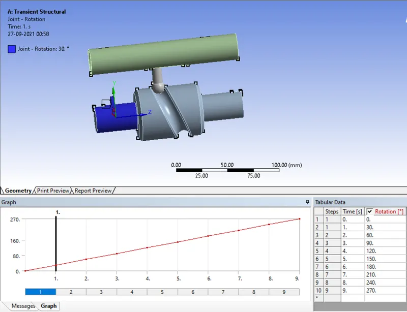
Analysis Settings :
Next we go to analysis settings to set up the kinematics of the simulation
The analysis is run for 9 steps using the following conditions. All the steps are chosen and the following criteria are entered as shown below.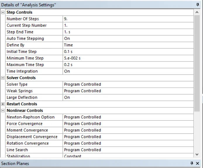
Output Parameters : The following parameters are selected for output from the simulation.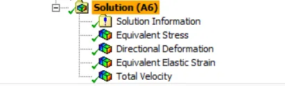
3 case scenarios are analysed for this simulation,all having different contact conditions:
1)Contact - Frictionless
2)Contact - Frictional (Co-eff 0.1)
2)Contact - Frictional (Co-eff 0.2)
Running the simulation :
Next we run the simulation. The simulation takes about 3 minutes to run as we can see from the runtime below.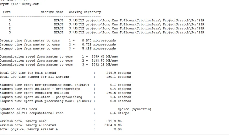
Post-processing :
Equivalent Stress :
Case 1)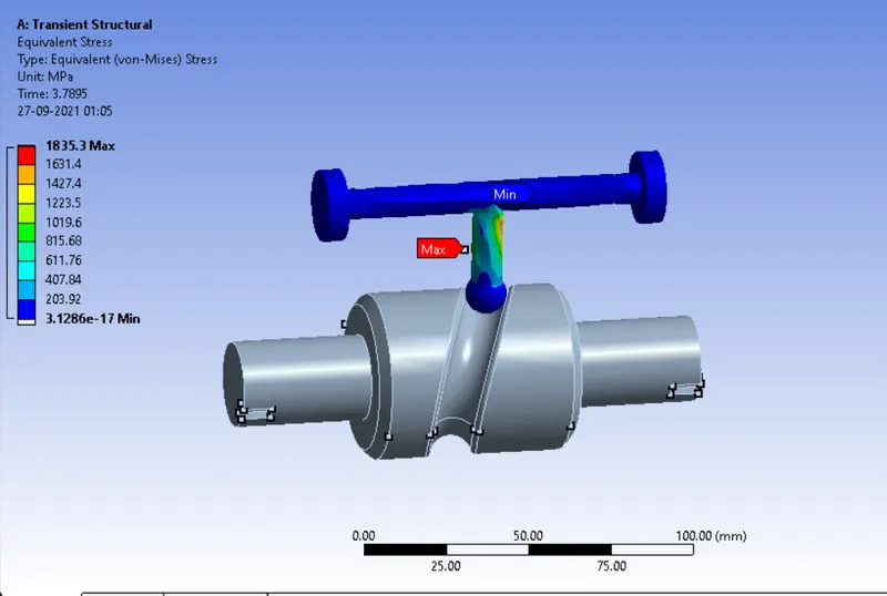
A peak stress of 1835.3 Mpa is obtained in the cam follower.
Case 2) 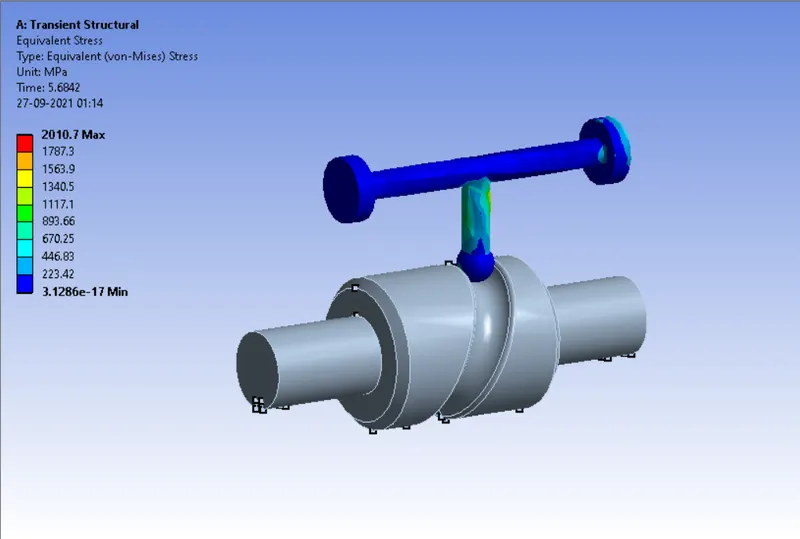
A peak stress of 2010.7 Mpa is obtained in the cam follower.
Case 3)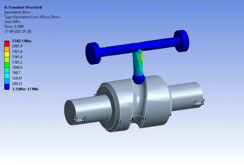
A peak stress of 2342.1 Mpa is obtained in the cam follower.
Directional Deformation :
Case 1)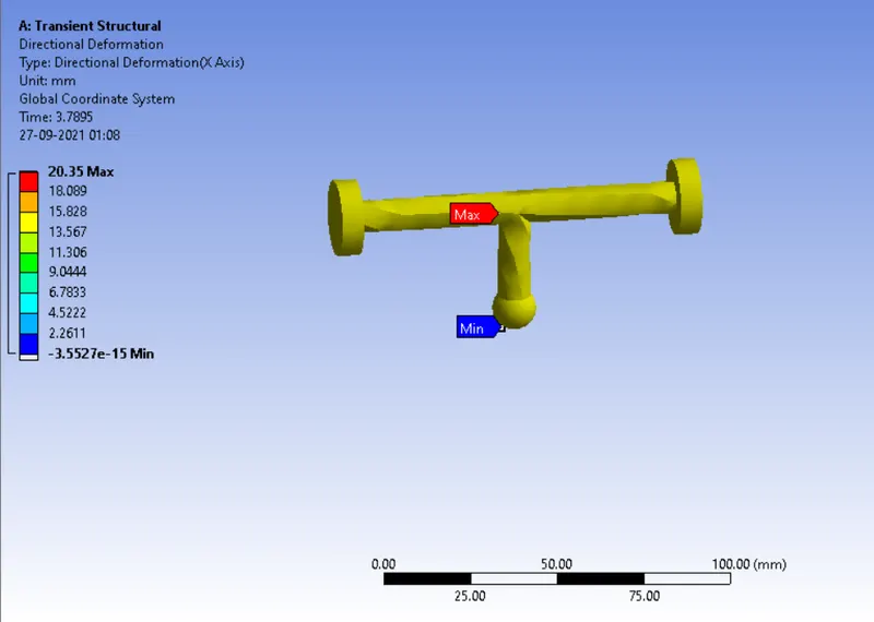
A directional deformation of 20.35 mm occurs in the follower.
Case 2)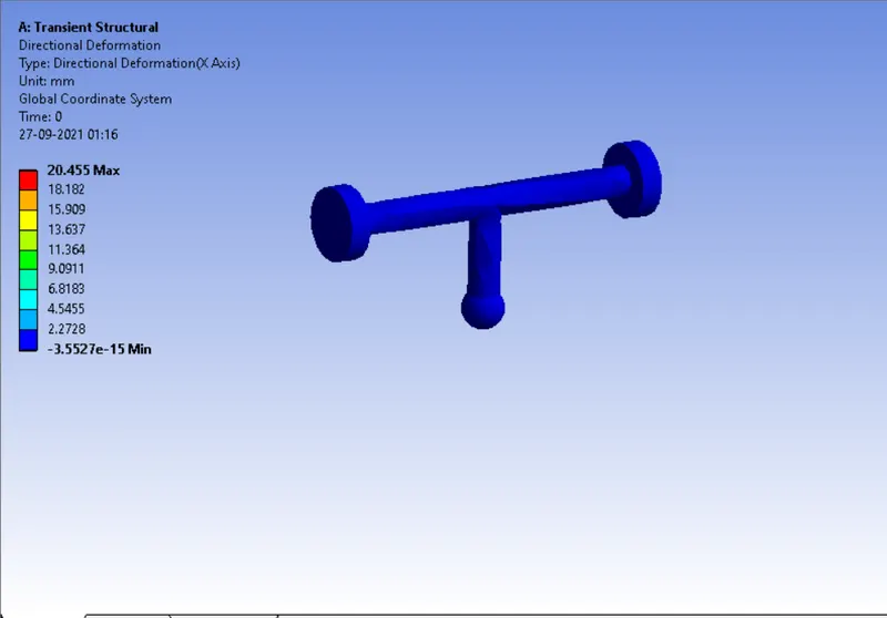
A directional deformation of 20.45 mm occurs in the follower.
Case 3)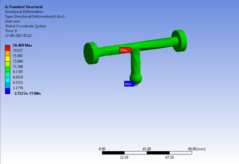
A directional deformation of 20.49 mm occurs in the follower.
Equivalent Elastic Strain :
Case 1)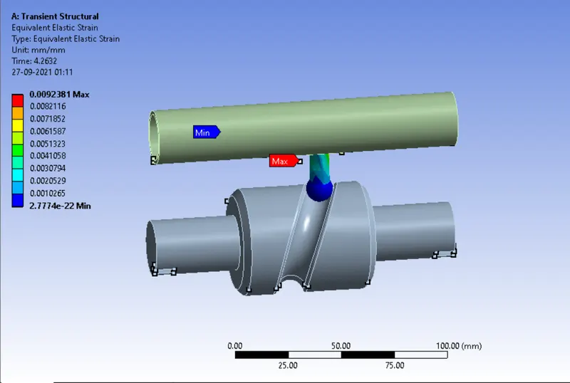
A deformation of 0.0092381 mm occurs on the follower. (independent of follower travel)
Case 2)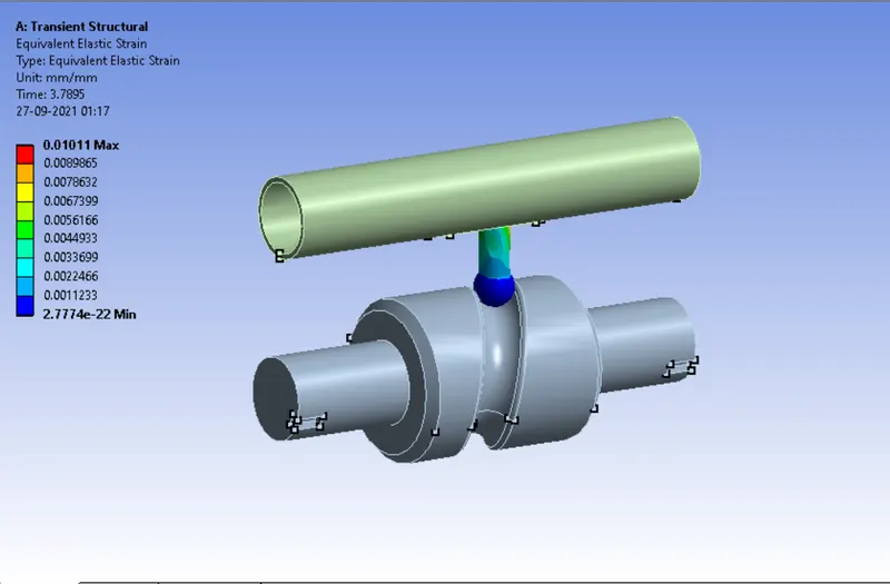
A deformation of 0.01011mm occurs on the follower. (independent of follower travel)
Case 3)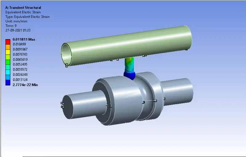
A deformation of 0.01181mm occurs on the follower. (independent of follower travel)
Conclusion :
The 2 cases have been simulated of clip travel and buckle travel.
The stress generated at base of clip is highest in case 3.
The deformation of follower is highest in case 3.
This shows that as the frictional coefficient increases the stresses and strains increase.
Result :
Error in attaching file directly. Hence attaching Google Drive Link
Long_cam_3_cases