Week - 5 - Modelling Spotwelds
Objectives : To study the impact behaviour of the two plates connected by spot welds onto a rigid wall and to study the various energies being generated.
Preocedure :
Setting up the simulation :
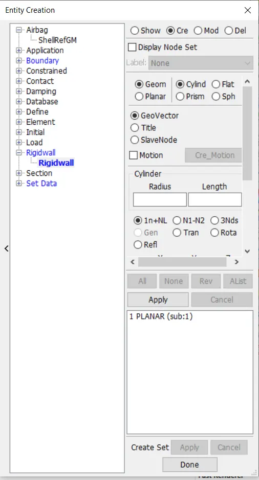
Creating the rigid wall : To create rigid wall go to create entity-->rigid wall-->create, choose the options as planar, select the tail node, click on translate option and give a tranlational of about 20mm.
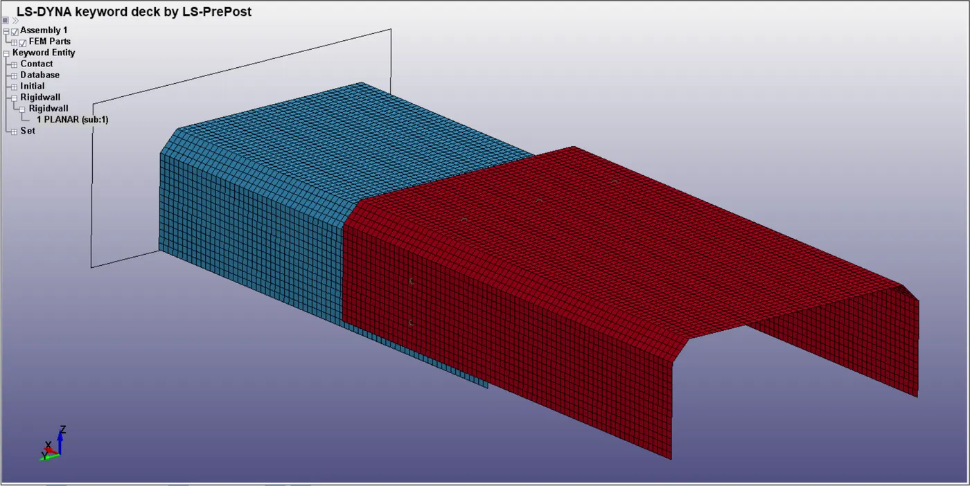
Hence the rigid wall will appear like this ahead of the two sheets.
Creating spot welds : To create material property go to elem-->elem generation and select beam element.
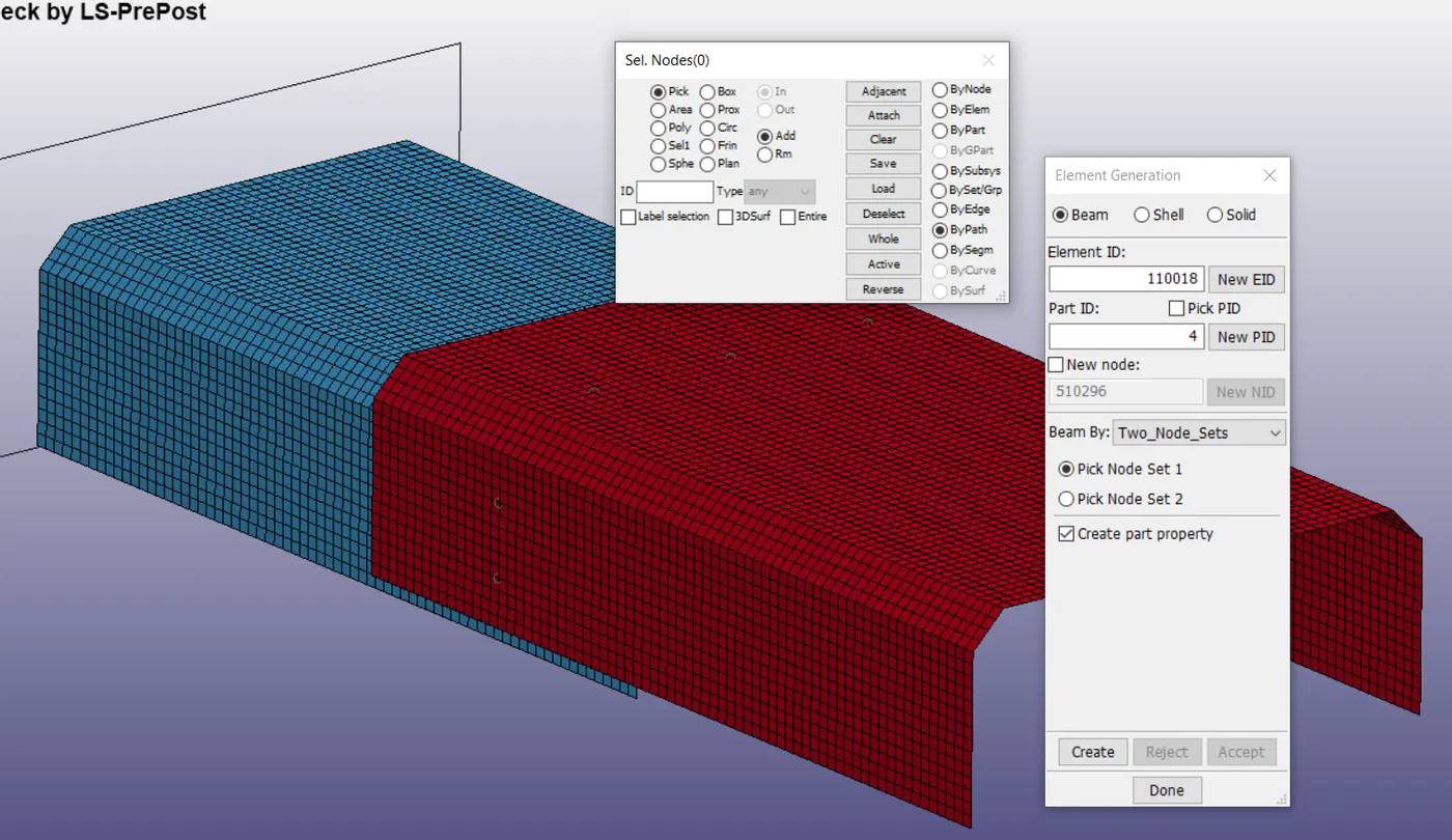
Select 2 node sets option and create the beam elements between the 2 node sets choosing them from the pick nodes option. A total of 7 beam elements are created.
Creating material property : To create material property go to MAT-->select card 001 and fill in the options suitably. For this material card, material information about stress and strain rates was also inputted from online sources as follows. Inputted unit system is g, ms, mm.
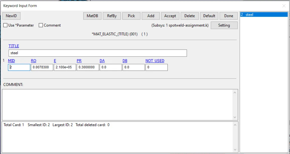
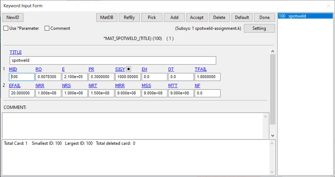
The material card chosen for spotweld is MAT 100 as shown below with the following values.
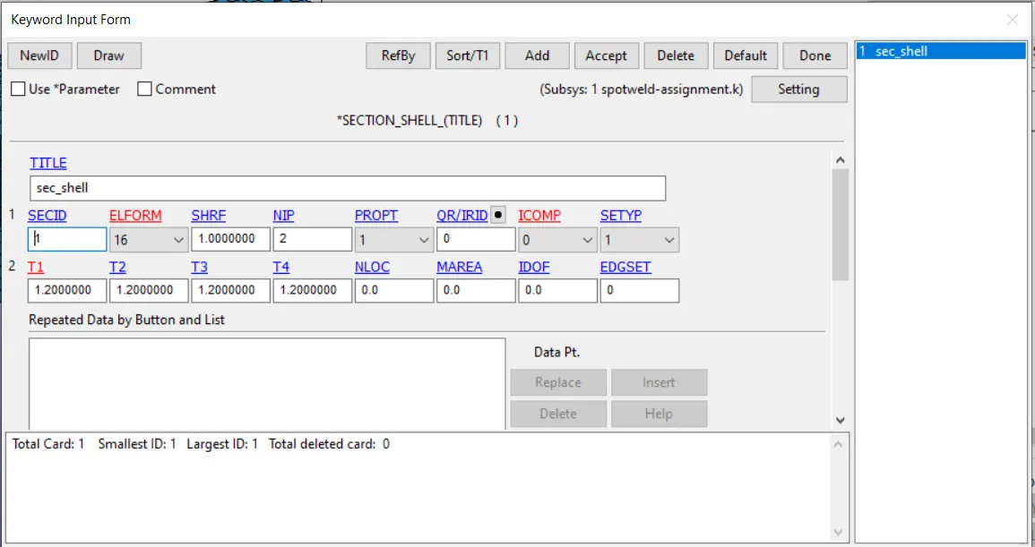
Creation of Section : Next we create a section by going to Section and selecting the following options in the card for shell elements. Assign a thickness of 1.2mm to the crash box.
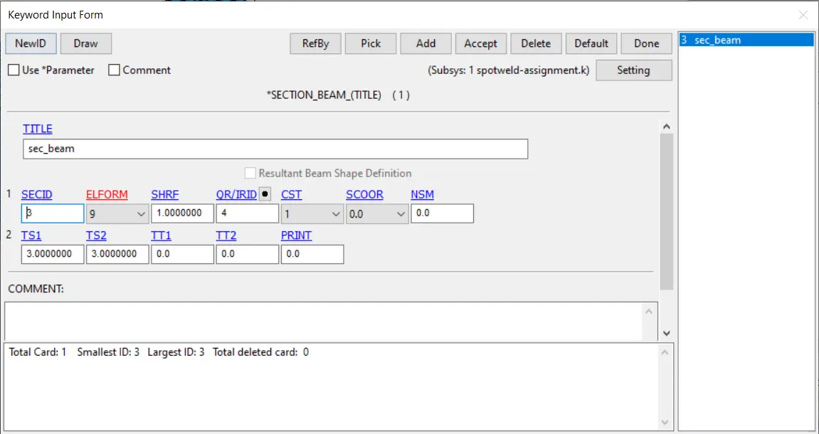
For the beam elements we create a section-->beam with the following parameters chosen as shown.
Assigning to part : Next, we assign the material and section to the shell_blue and shell_red which share the same material and section by entering the material and section Ids in MID and SECID respectively.
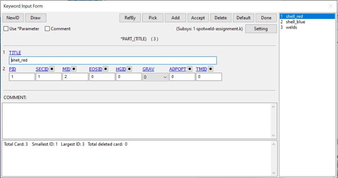
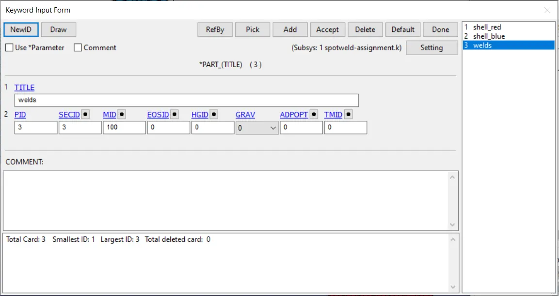
Similarly for the welds we create a separate part card as shown below
Defining Contact : Next we define the contact between the shells and the weld elements for which we use
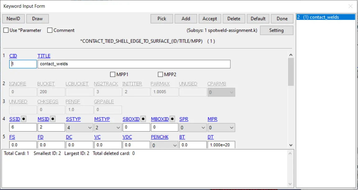
CONTACT_TIED_SHELL_EDGE_TO_SURFACE, and enter in the following values and define the slave as nodeset ID of the weld nodes. We select the master surface as part set ID of the two shell parts. The name is given as contact_welds.
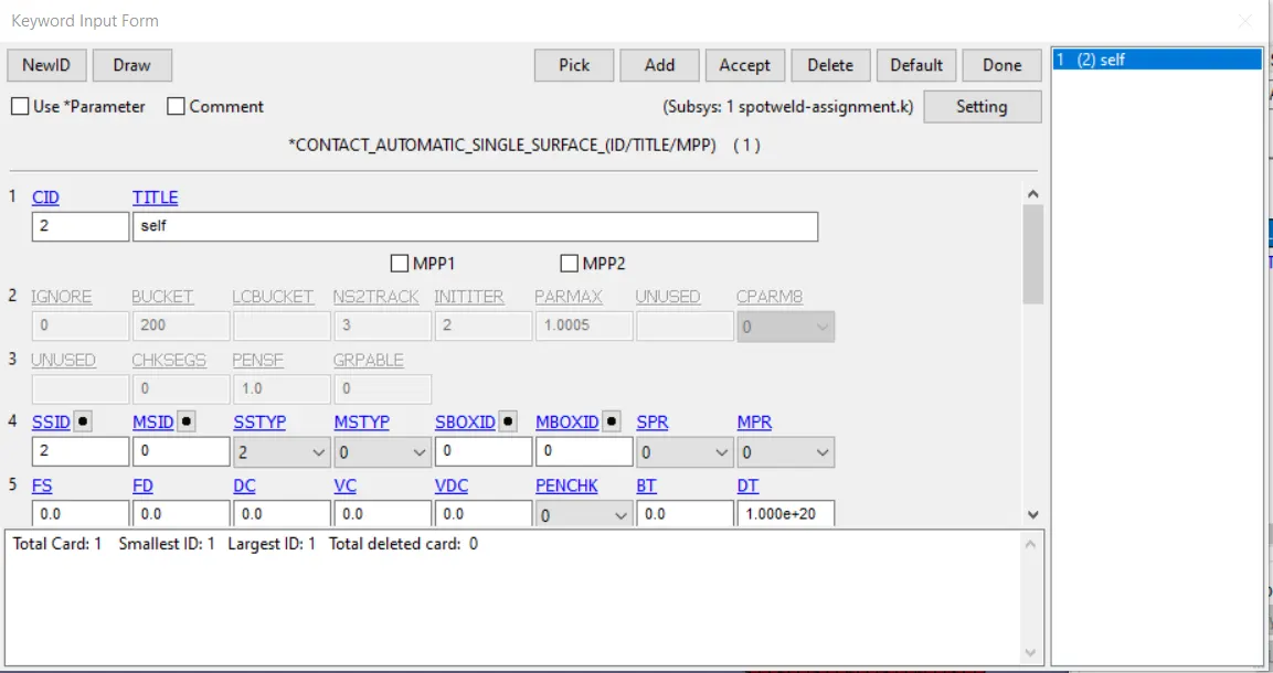
Next we define the contact for the crash box to collide with itself. We go to contact and choose
CONTACT_AUTOMATIC_SINGLE_SURFACE_, and enter in the following values and define the slave as partid of the box. Give the name as "self".
Assigning Initial Velocity :
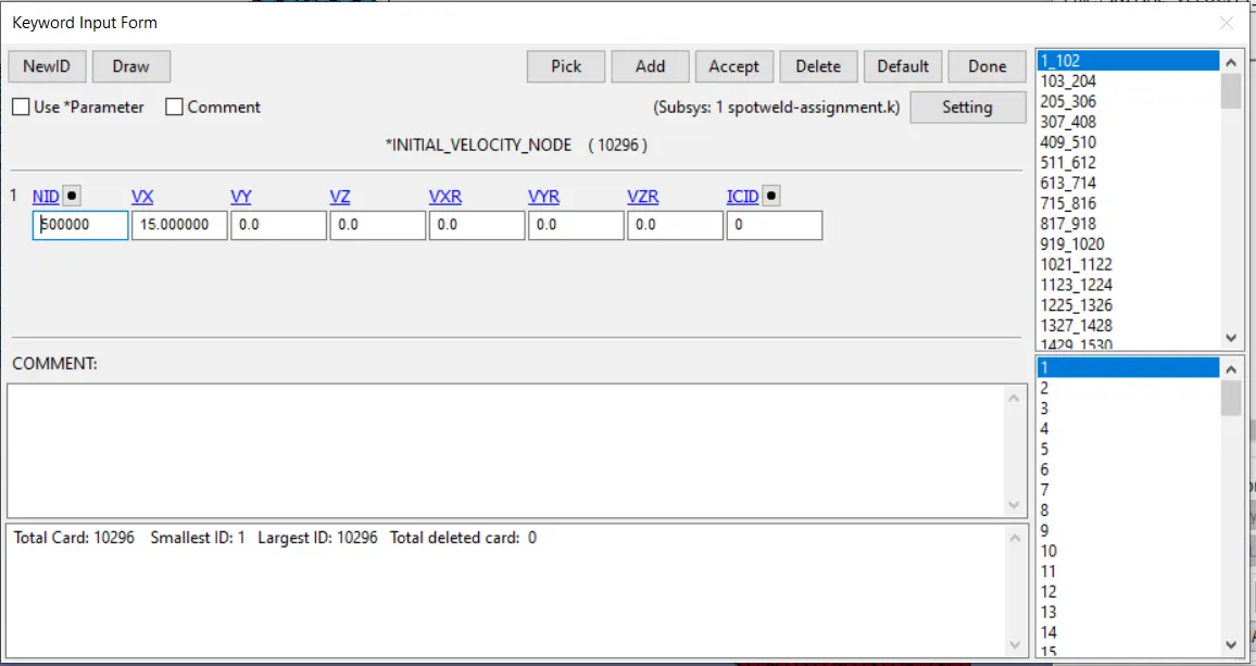
Go to create entity-->Initial velocity-->create and then pick-->by part to create an initial velocity assignment to the two shell parts. The velocity of 15 mm/ms is given to the parts in x-axis.
Control parameters : Next we select the control parameters, which govern the conditions in which the simulation will be computed.
Control_termination:
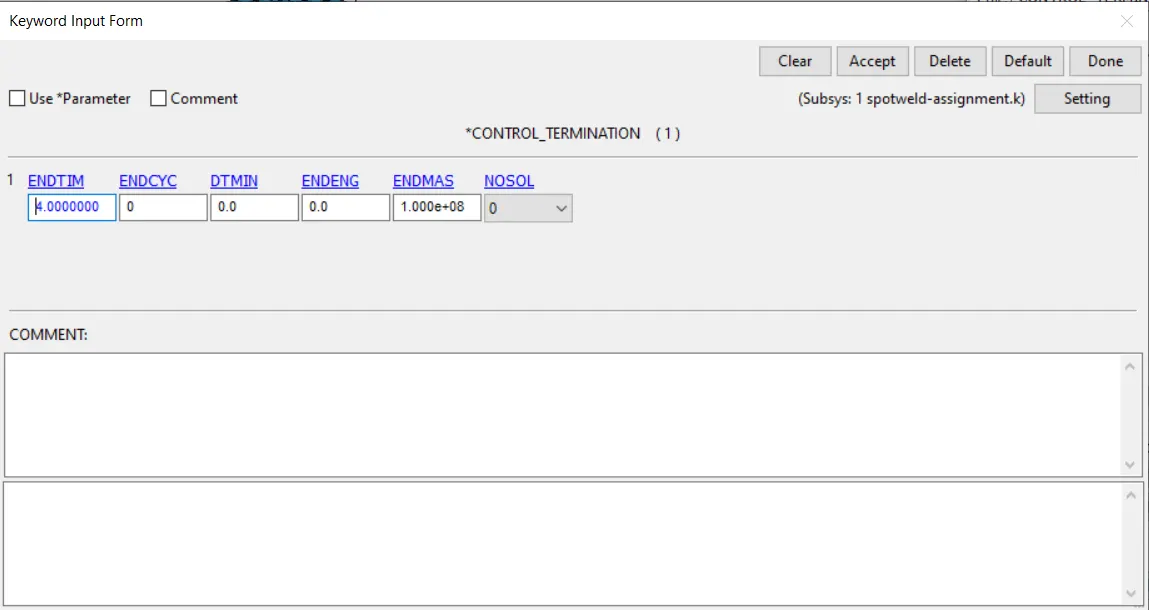
Based on the velocity of the parts and the gap to the rigid wall, a termination time of 4ms is chosen as shown above.
Database options : Next we select the options which we want to see in the output characteristics. The following options are selected in Database_ascii. The options GLSTAT,RCFORC, SWFORC, ELOUT are shosen to show the energy curves, rigid wall force, weld forces, and element forces respectively.
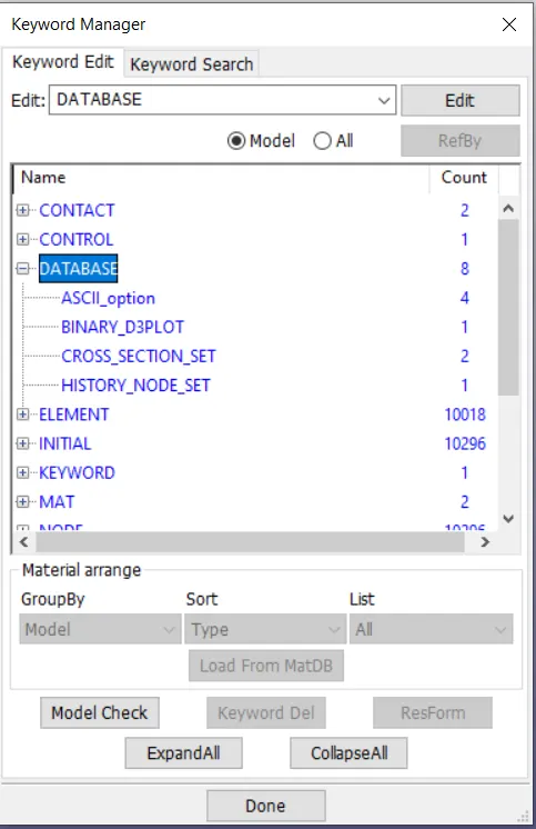
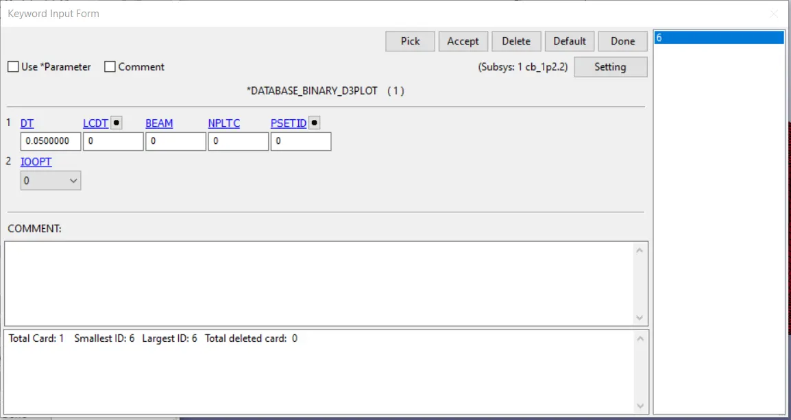
The following options are selected in Database_binary_plot. The timestep is kept at 0.05 milliseconds as shown below.
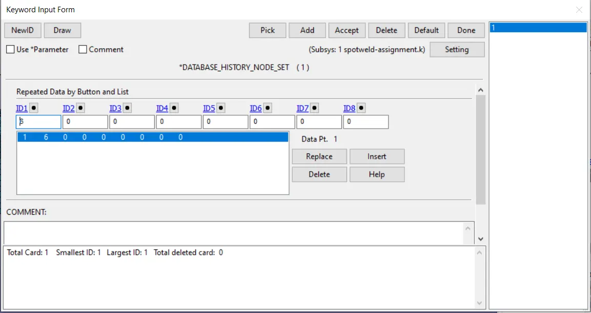
Next we create history node set to see the forces acting on the nodes of the welds as shown below.
Now all the pre-processing is complete and we are ready to run the simulation.
Running the simulation : Now we will run the simulation.
Post processing :
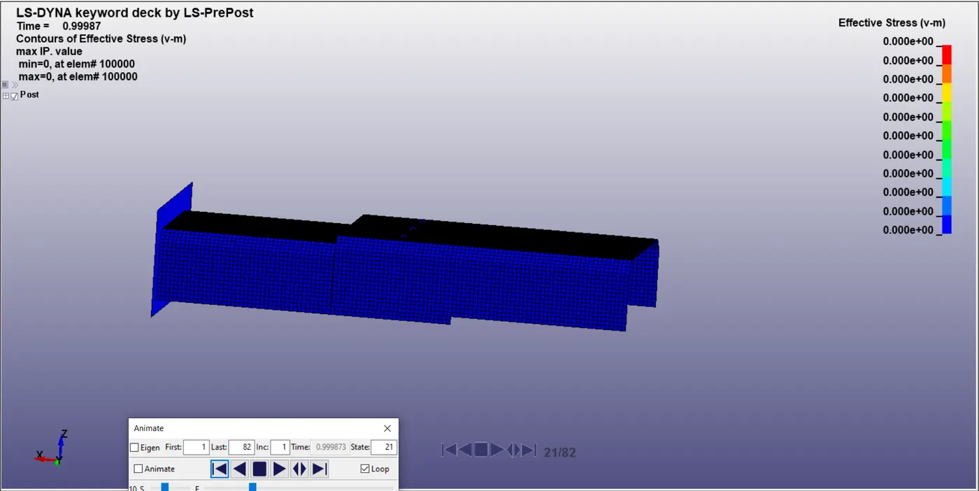
Crash behaviour : We can see that the our system aprroaches the rigid wall at the given speed of 15 m/s, compresses very minutely and bounces off the rigid wall with quite a bit of plastic deformation. The crash happens between 20 and 21st frame out of a total 82 frames.
We can see that at the 22ns frame the shockwave propogates through the first shell and gets transferred to the second shell through the weld beam elements.
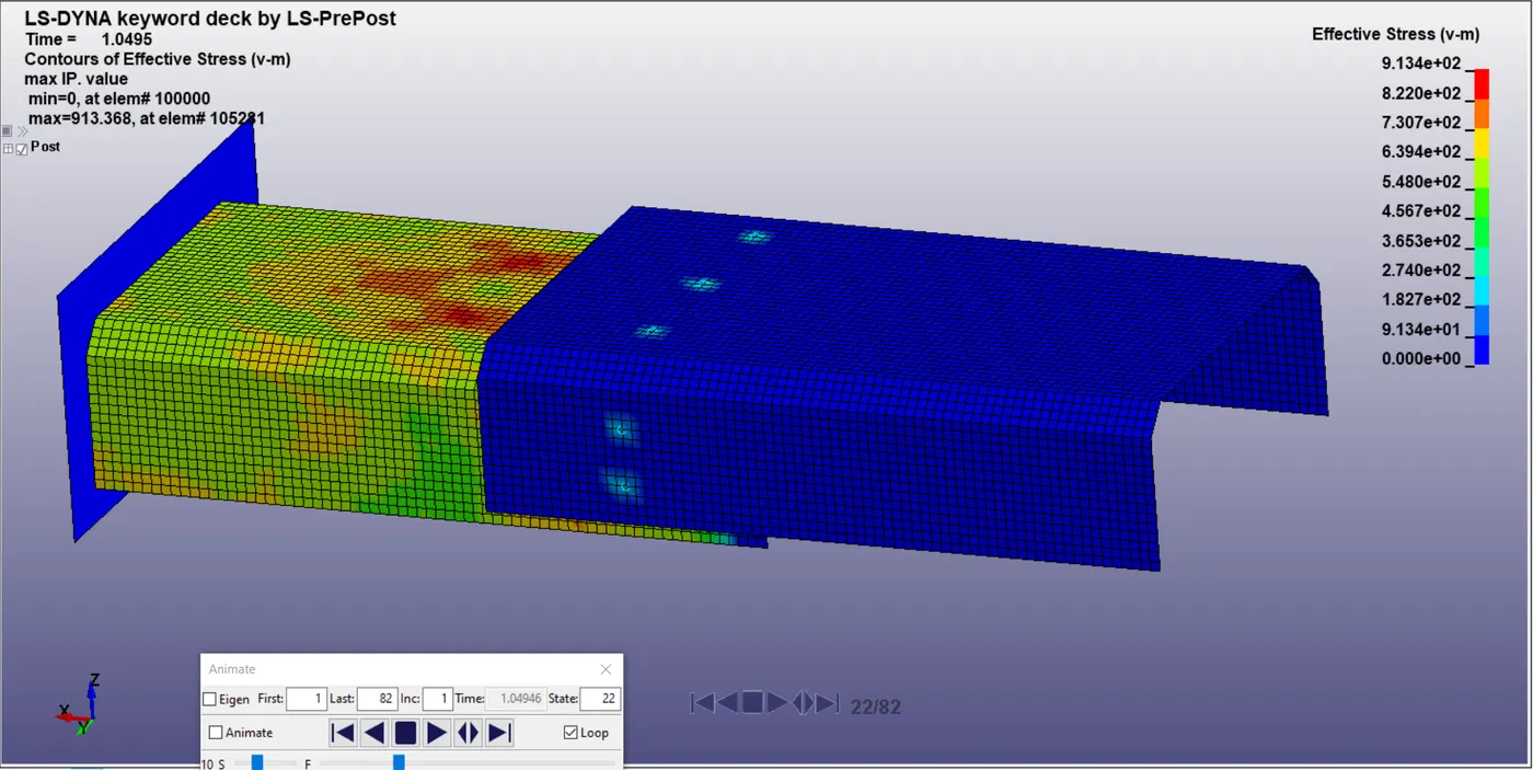
In the frame above we can see that the nodes of the second shell where the weld elements are present experience the first stress in this shell of around 182Mpa.
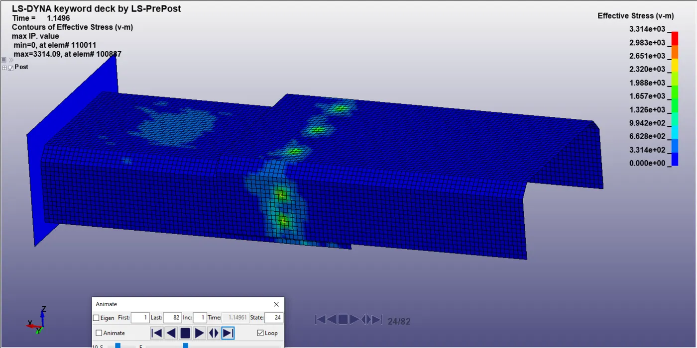
After initial contact the system rebounds off the rigid wall and the shockwave that travelled through the system makes the elements(atoms) oscillate about their mean position causing periodic stress inducement for a while until due to natural damping the system tries to return to equilibrium.
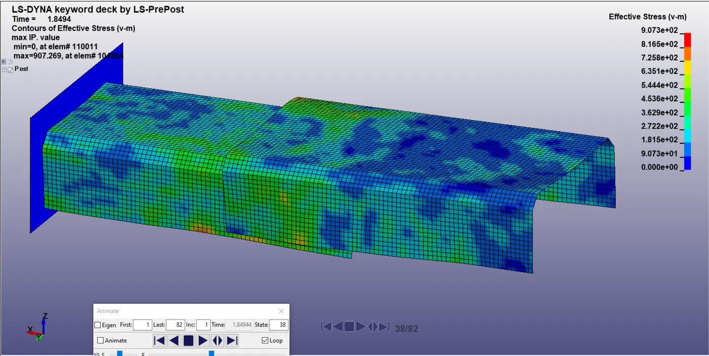
As the weld elements fail at the 38th frame due to failure time of 1.8 ms which we have given, after this point the stresses have already been induced in both the shells and now they continue to move independent of each other as they are not connected anymore.
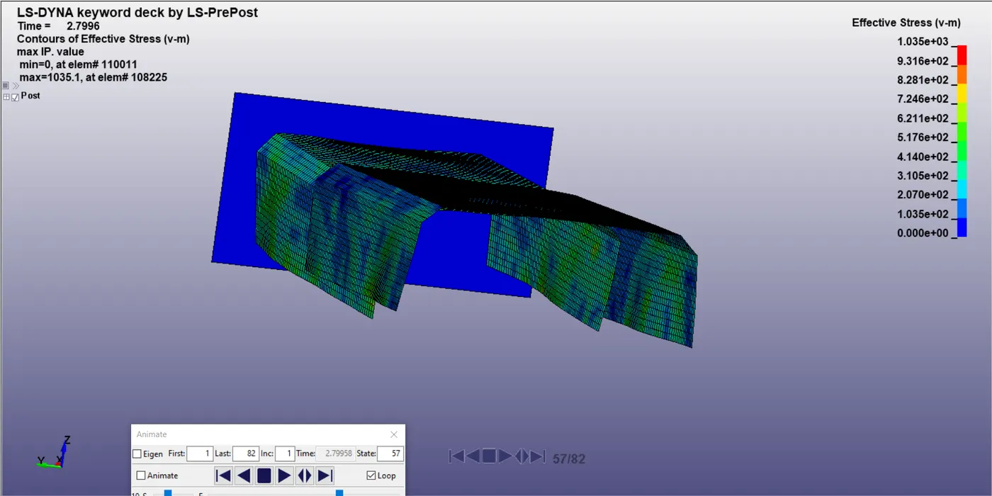
In the above picture we can see the deformation of the system sue to the crash and it continues increasing till the end of the simulation.
A peak stress of around 1386.5 Mpa is experienced at around the 48th frame as shown below.
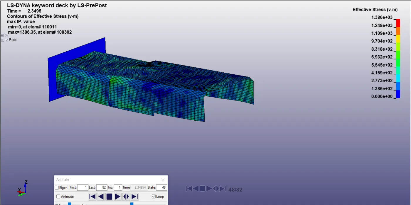
Normal stress along the length of the crash box :
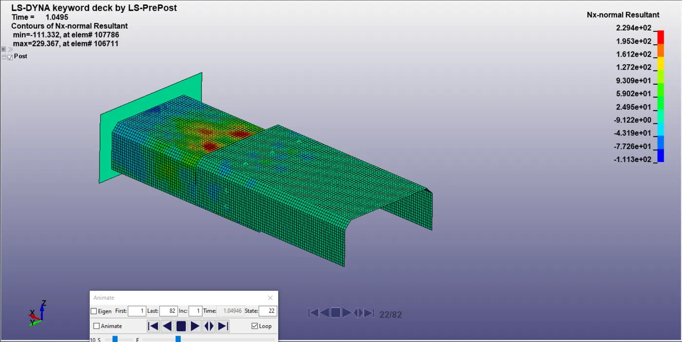
The normal stresses acting in the x-direction at the frame just after collision are 229.36 Mpa. We can see the stress pressure points developing infront of the welds due to resistance being provided by them to move independently.
Forces at weld elements (beam) :
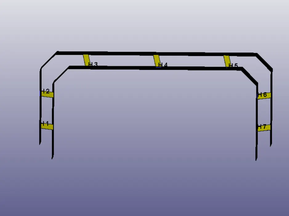
Here we can see the axial and shear forces at the weld-beam element 110011. This is the particular weld whose forces we are seeing. The picture below gives us an idea of where which weld element is located.
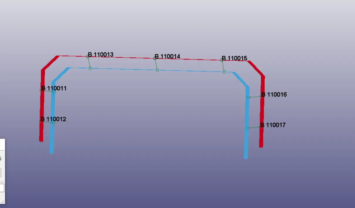
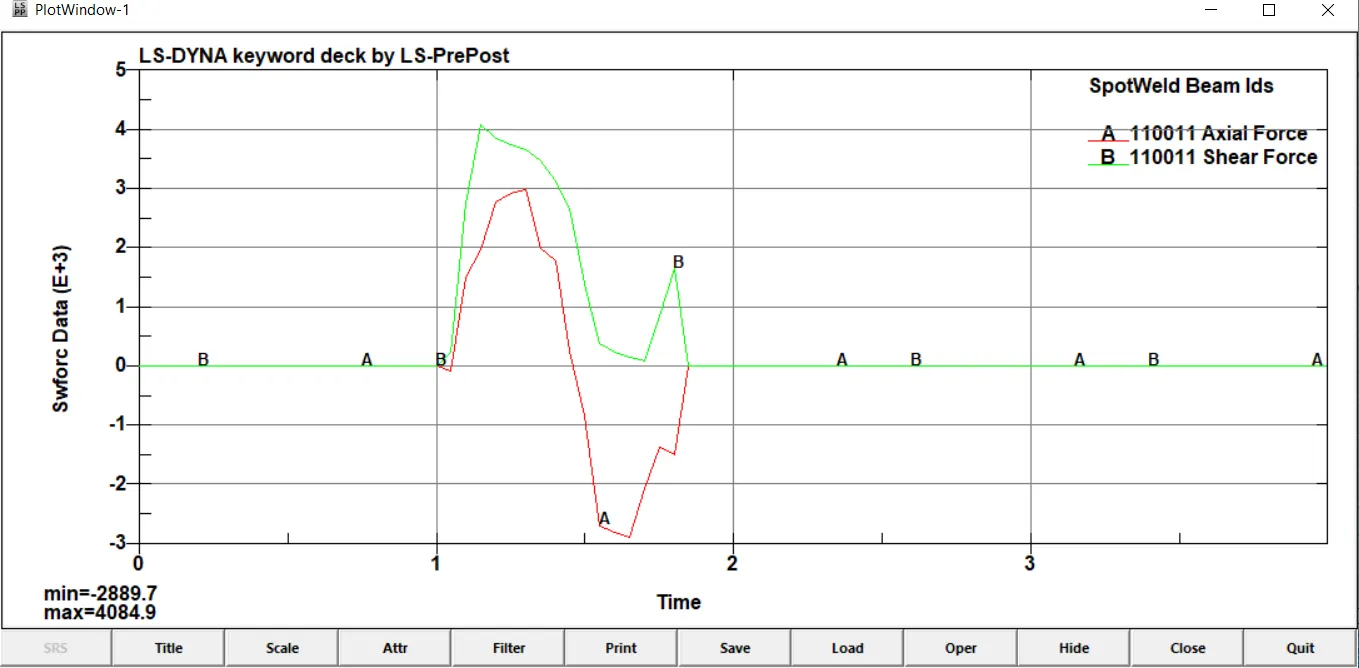
As we can see in the picture above, the forces in the weld develop right after the collision with the rigid wall. A minimum of 2889.7N in negative direction of axial force and a maximum of 4084.9N in positive direction of shear force is experienced in this particular weld element.
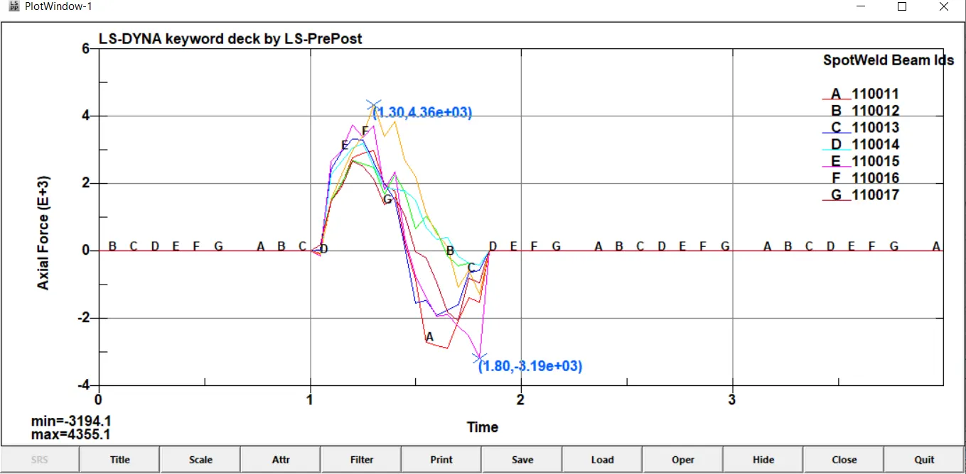
Below we have plottd the axial forces of all the weld elements with the maximum of 4355.1N in positive direction and minimum value of 3194.1N in negative direction being given in the bottom left corner.The positive and negative direction indicates the alternating of tensile and compressive forces being experienced by the welds due to their somewhat elastic nature. As we can see the tesnile forces exceed the compressive forces.
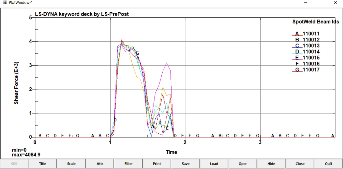
Below is a plot of the shear forces of all the weld elements. We can see that the weld elements go through two spikes of shear force before becoming zero after they fail at the specified time. A maximum of 4084.9N of shear force is experienced among all the weld elements. As we can see the weld element 110015 experiences the most shear force combined in both the spikes with around 3800N and 3100N respectively.
Forces at weld elements (solid) :
Next we will study the weld forces on the solid weld elements. The solid weld elements are created at the same location as the beam elements but instead of using beam we use solid option. The solid welds look as shown below with their respective part IDs :
Given below is the axial and shear force distribution of weld 1.
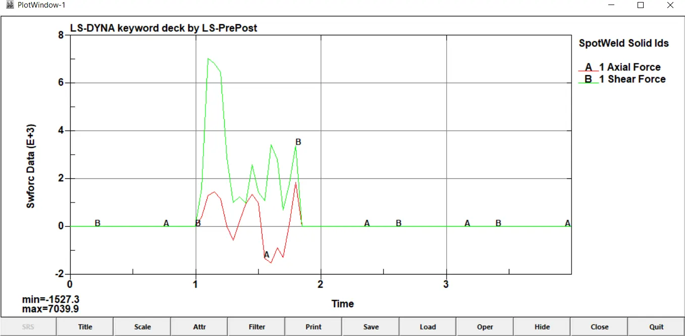
As we can see above the value of axial force is reduced to a large extent and this reduction directly translated to an increase in shear force. The peak shear force is obtained at 7039.9N and the maximum axial force is 1850N in positive direction. This is due to the shape of the weld element. As it has a square cross section and force being applied to it in the x-direction gets mostly converted to shear force and the axial force gets reduced significantly.
Hence it shoes that by using solid elements for weld, the shear force is being experienced to a greater extent as compared to axial forces.
Given below is a plot of shear forces of all the solid welds.
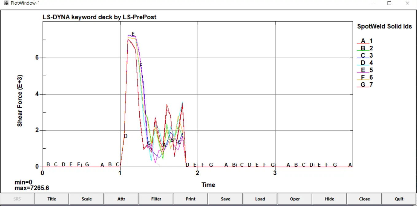
We can see that as compared to using beam elements where there were only 2 peaks and crests in shear force, here there are 4 meaning that the frequency of force transmission in solid weld elements is higher for a given time period. This may be due to the fact that there is more cross section area available for transmission of the force. A maximum of 7265.6N is experienced in shear forces. Weld element 1 has forces increasing after the initial dip whereas the rest of the elements taper off the forces after the intial maximum force experienced as is evident from the graph.
Given below is a plot of axial forces.
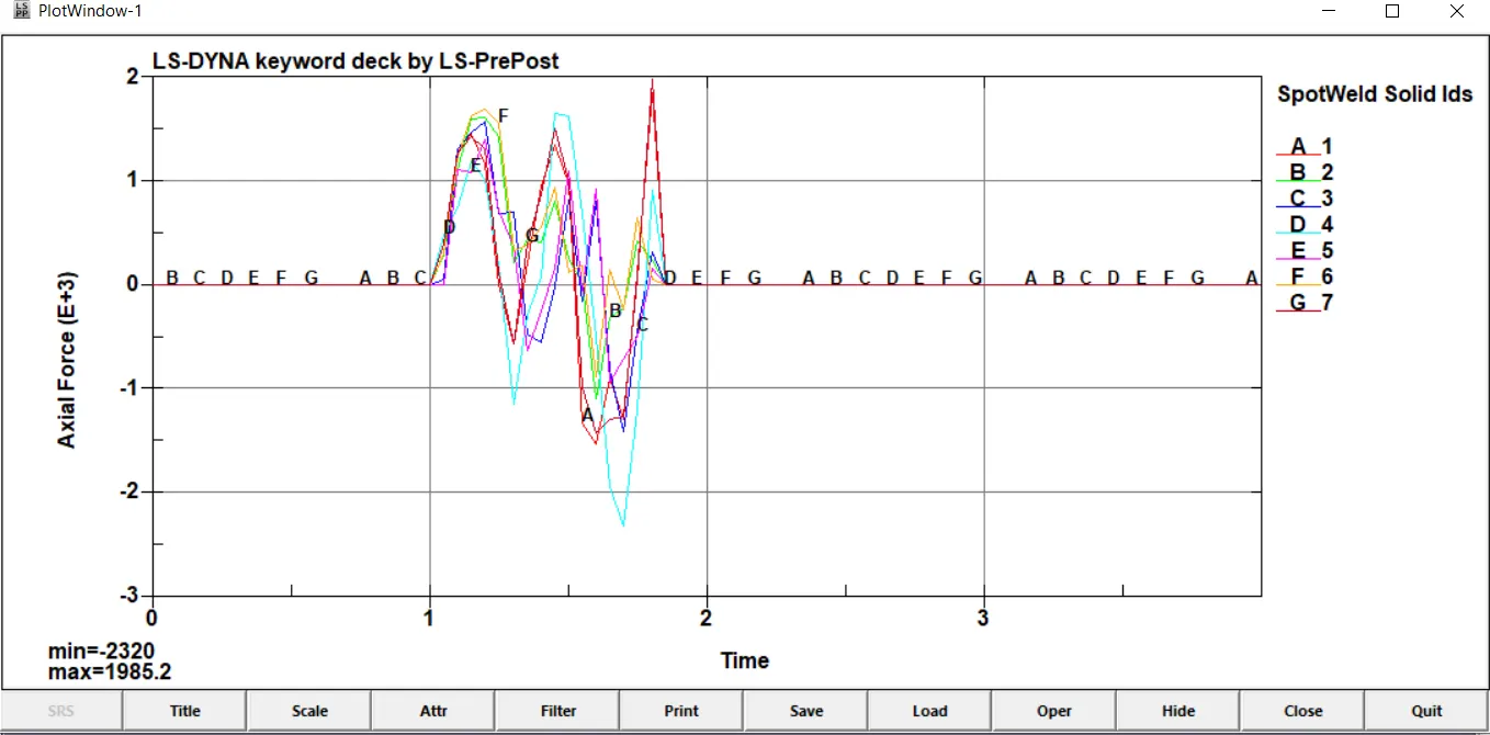
We can see that the axial forces experienced by the beams undergo an alternating compressive and tensile behaviour with a maximum of 1985.2N (tensile) and a maximum of 2320N (compressive) forces being experienced by the weld elements. The weld element 1 forces increase towards the end as was seen even in the shear forces plot.
A total of 3 peaks and 2 crests are experienced by the members indicating 3 instances of tensile forces and 2 instances of compressive forces. As mentioned earlier the axial forces are much lesser in comparison to the shear forces when compared with the beam element force distribution.
Plot of Energies :
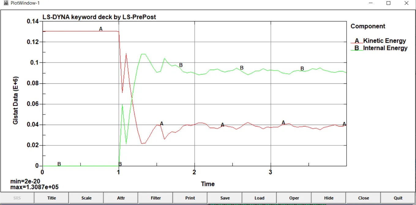
Internal Energy v/s Kinetic Energy:
Beam element weld :
Solid element Weld:
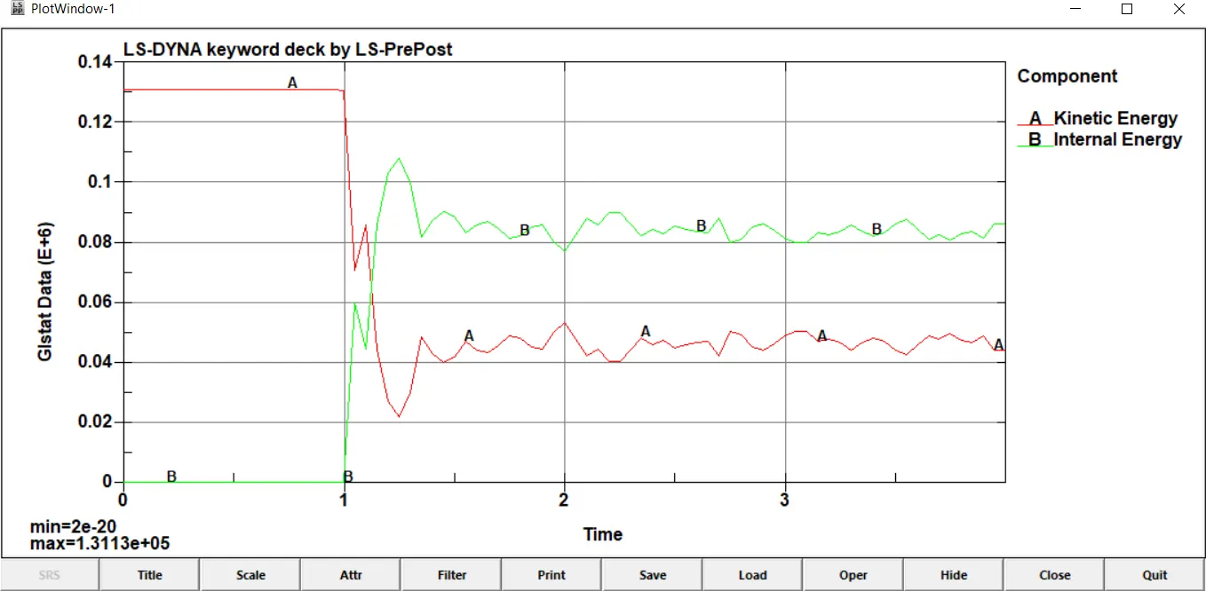
As we can see the amount of Kinetic Energy lost is the amount of internal energy gained more or less with few losses indicating the simulation has good energy balance and is accurate. The energies are of the order of 10^6 N-mm.
It appears above that the solid element welds have a better damping of the energies after the inital contact as the graph for solid weld energies is more smoother.
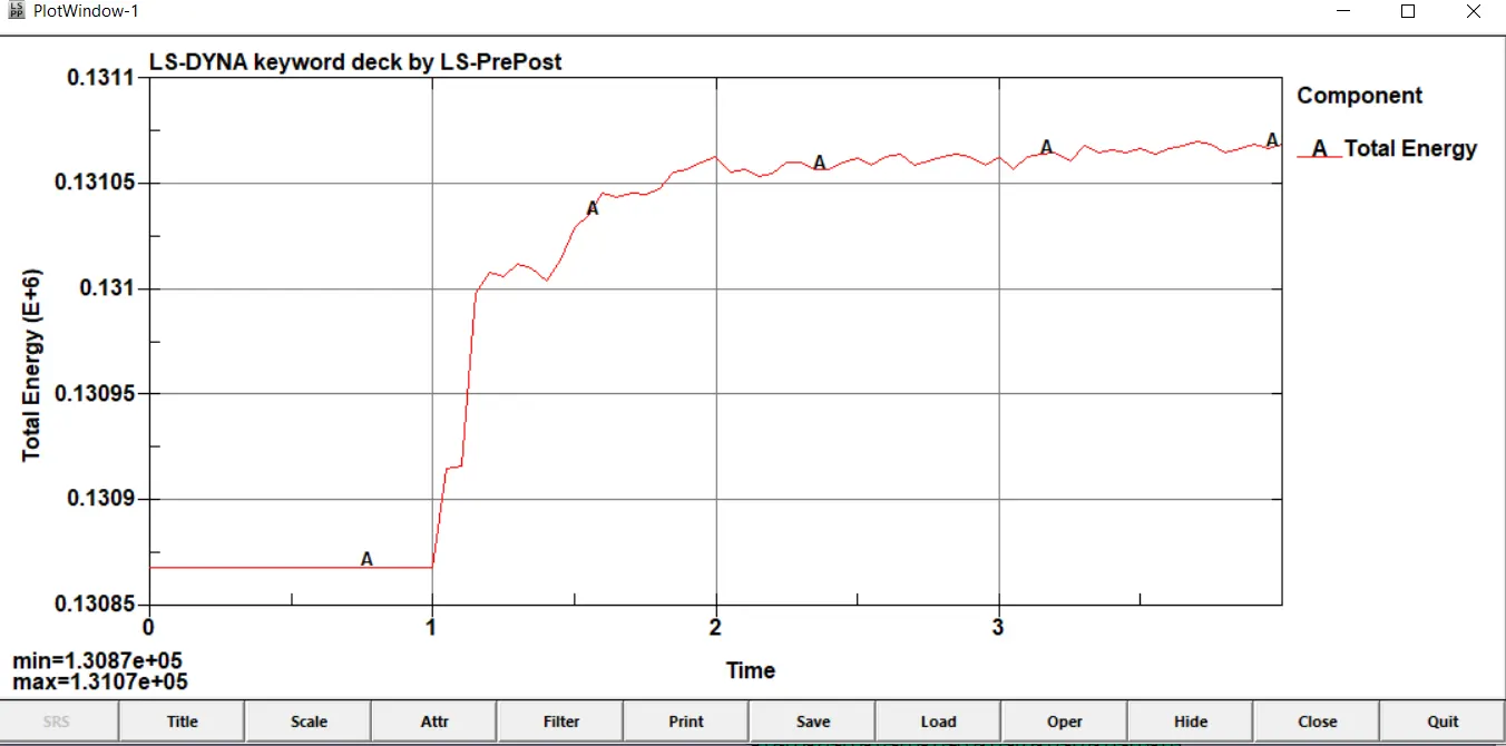
Total Energy :
Beam weld :
Solid weld :
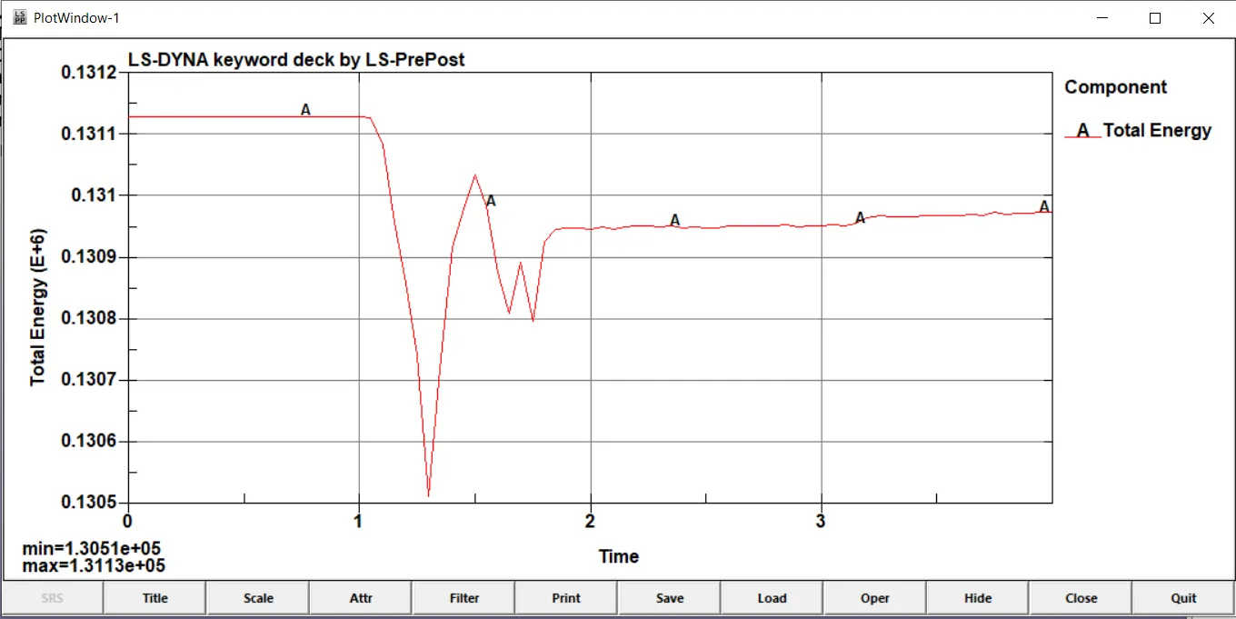
The total energy of the simulation ends higher than it started for beam elements but remains lower than it started for solid elements although the difference is not much
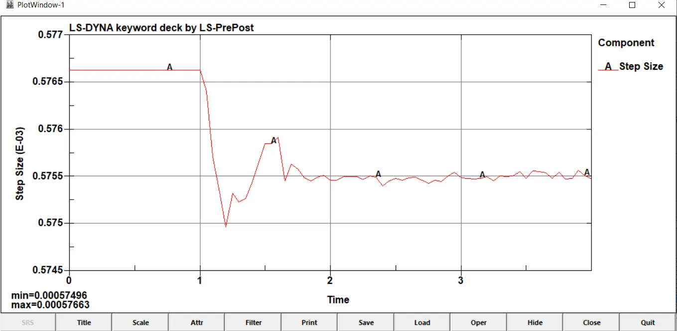
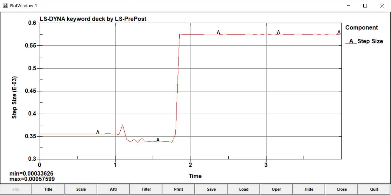
Timestep :
Beam weld :
Solid weld :
Conclusion : Hence we have successfully studied the behaviour of different types of weld elements in a crash scenario, how they experience forces and all the required parameters of the crash
Result :