Week 8 - Universal Joint
Objective : To setup the simulation of the given universal joint mechanism to obtain the desired results.
Setting up the simulation
To set up the simulation, first we need to import all the required material cards such as Structural Steel, Stainless Steel and Titanium Alloy
The below materials can be found in the General materials library.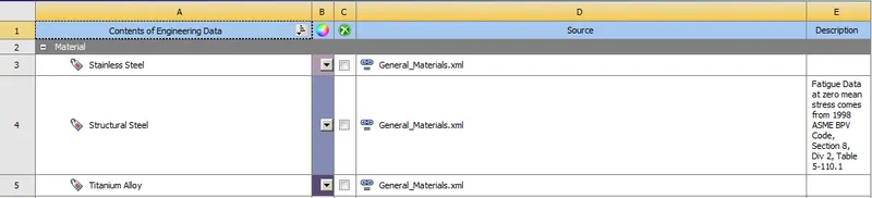
Importing geometry :
Next we import the geometry and rename them as Input_shaft, Output_shaft, Spider_1, Spider_2, Connector
Material definition : Structural Steel
Then we will open Ansys mechanical to set up the rest of the simulation.
Joints : Next we create the joints to facilitate movement of the Universal Joint mechanism in the appropriate manner.
Fixed - Ground to Output_shaft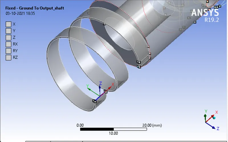
Revolute-Ground to Input_shaft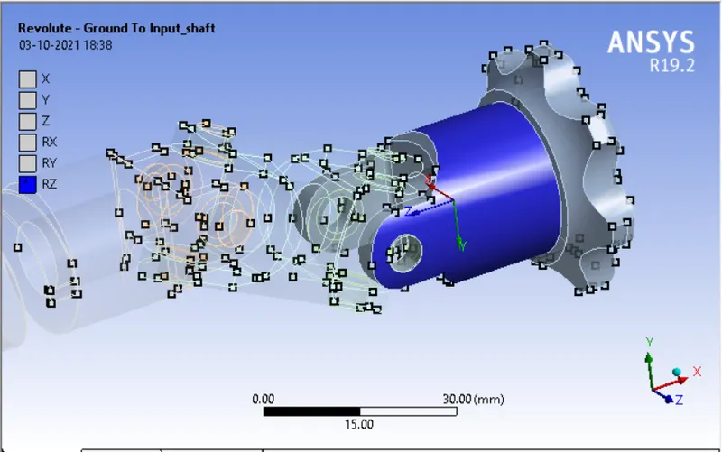
Revolute-Ground to Output shaft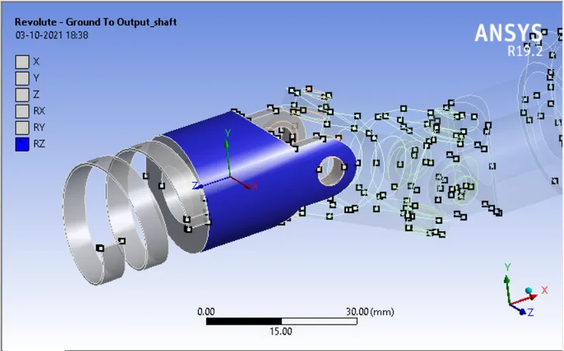
Next we create the joints to simulate the Universal Joint. 8 total joints are created as shown below.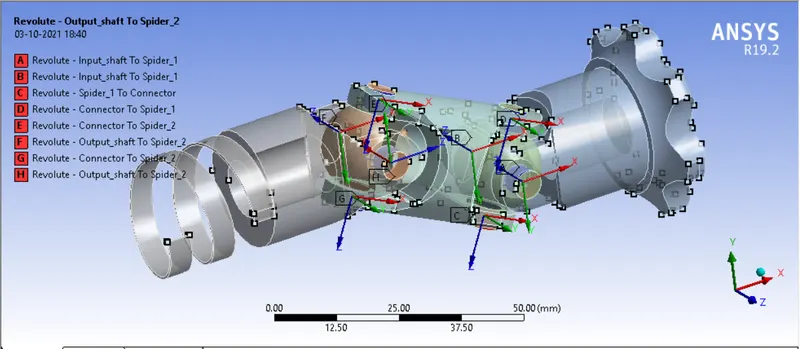
Mesh : Next we mesh the components.
A mesh size of 3mm is applied to the entire assembly.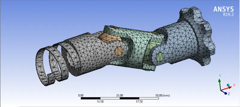
Analysis Settings :
Next we go to analysis settings to set up the kinematics of the simulation
The analysis is run for 4 steps using the following conditions. All the steps are chosen and the following criteria are entered as shown below.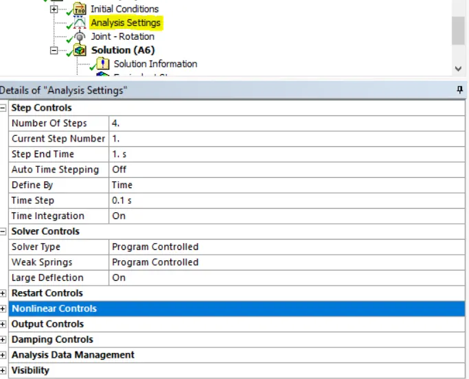
Joint-Loads :
A joint load is applied to the ground to input_shaft revolute joint in angular increments as shown below.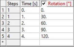
Output Parameters : The following parameters are selected for output from the simulation.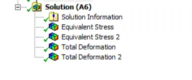
The equivalent stress and directional deformation are selected as output parameters, especially for the output shaft
3 case scenarios are analysed for this simulation, both have differeing positions of the pushing fingers as shown below :
Case 1: Output_shaft assigned as Structural Steel
Case 2: Output_shaft assigned as Stainless Steel
Case 3: Output_shaft assigned as Titanium Alloy
Running the simulation :
Next we run the simulation. The simulation takes about 10 minutes to run as we can see from the runtime below.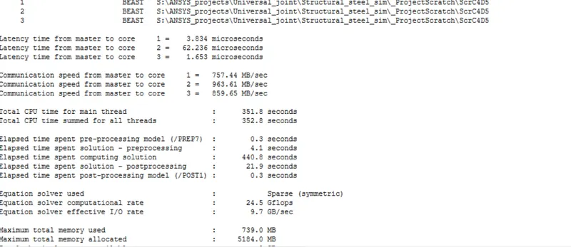
Post-processing :
Total Deformation :
Case 1)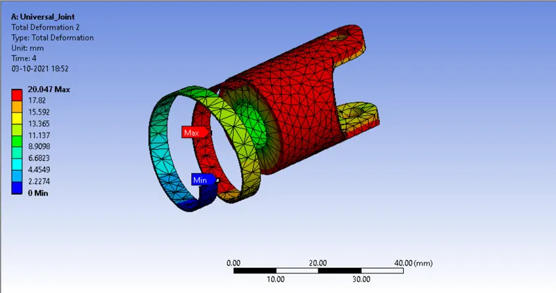
A total deformation of 20.047 mm occurs in the the output_shaft spring.
Case 2) 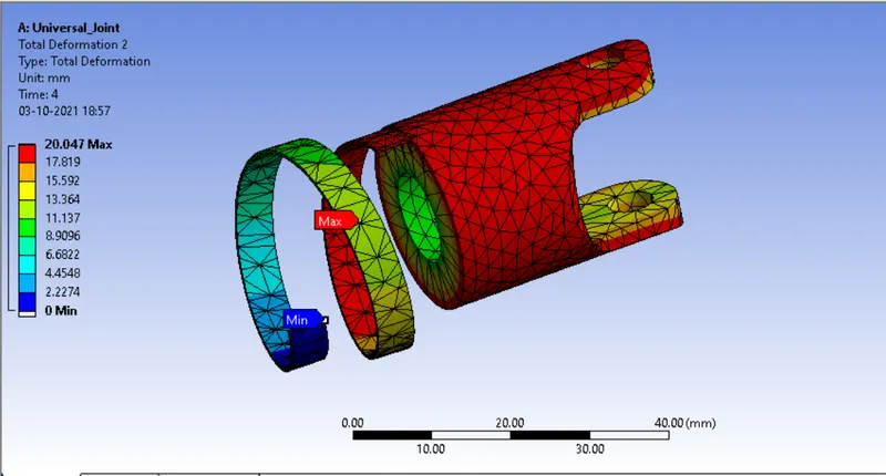
A total deformation of 20.047 mm occurs in the output_shaft spring.
Case 3) 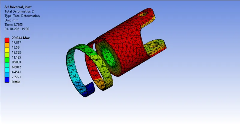
A total deformation of 20.044 mm occurs in the crank.
Equivalent Stress :
Case 1)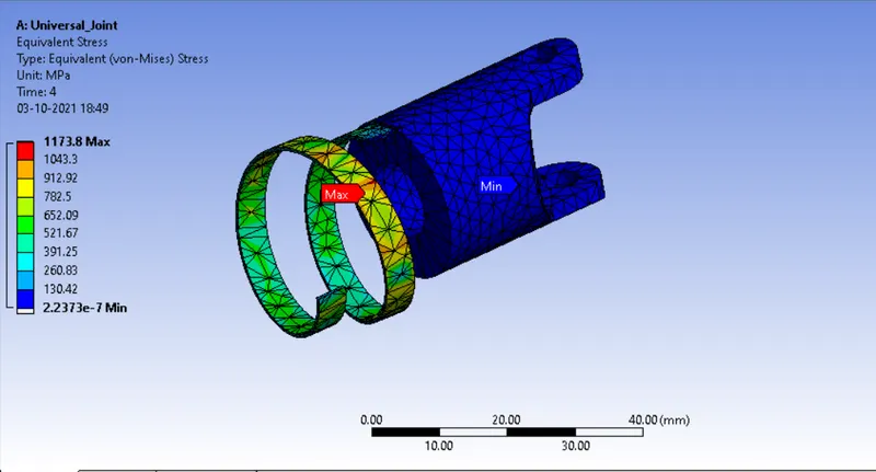
A maximum stress of 1173.8 Mpa occurs in the output_shaft spring.
Case 2)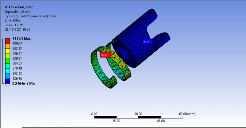
A maximum stress of 1135.5 Mpa occurs in the output_shaft spring.
Case 3) 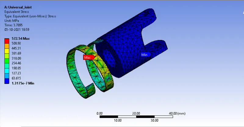
A maximum stress of 572.54 Mpa occurs in the output_shaft spring.
Conclusion :
Hence the simulations have been run as per the desired criteria and the results have been obtained.
The stresses occuring in the crank are highest in case 1 in the output_shaft spring
Result : File cannot be attached. Attaching google drive link.
Simulations_3_cases