Week 3 Verification of Weld Joints
Objective :
To setup the given simulation to test to charachteristics of the welds and how they affect the deformation of the metal plates by changing the materials and observing the behaviour.
Procedure :
Setting up the simulation :
To set up the simulation, first we need to import all the required material cards such as Stainless Steel, Aluminium alloy(high strength, wrought) and Cast Bronze.
The above materials can be found in the Granta materials library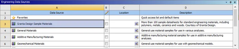
Stainless Steel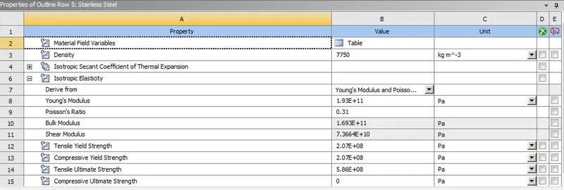
Aluminium alloy(high strength, wrought)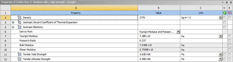
Cast Bronze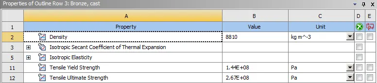
Importing geometry :
Next we import the geometry which is the Creo CAD file of the plate setup which has been provided.
Material defintion : 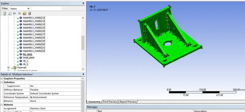
The material stainless steel is assigned to all the components including plates & welds for the first case.
Then we will open Ansys mechanical to set up the rest of the simulation.
To set up the contact we go to connections-->contacts and select rename based on definition.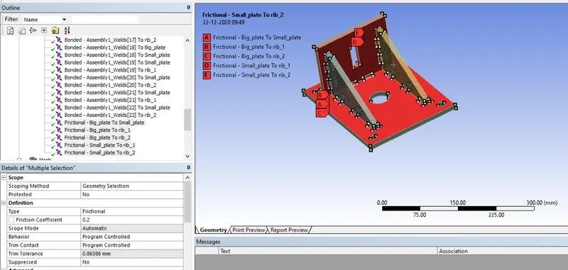
For the last 5 contacts, as they are between the plates, we will change the type to frictional with the coefficient of friction as 0.2
Type = frictional
Coefficient of friction = 0.2
The rest of the contacts as they consist of the weld elements we will let them be as Bonded type.
Next a mesh is generated.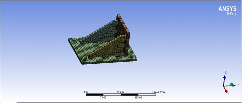
We use body - sizing to generate mesh sizes for different components as shown below.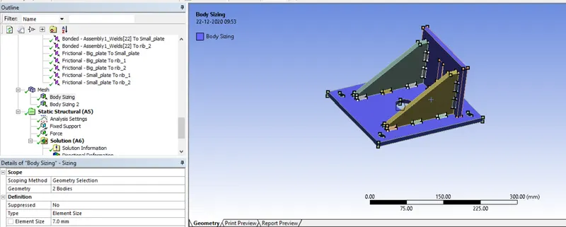
For the 2 plates, we use a mesh size of 7mm as shown above.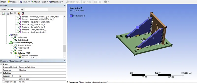
For the 2 ribs, we use a mesh size of 9mm as shown above. This concludes the mesh generation.
Creation of Loads :
Next we define the physics of the problem.
We will make the big plate fixed using the holes on its surface using Fixed Support option as shown below.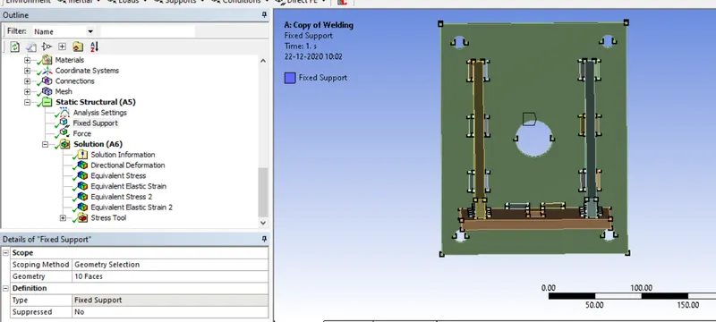
Then we assign a force the the perpendicular plate along the rectangular slit as shown below. A force of 15000 N is applied in the downward direction to pull it in a perpendicular direction to the big plate.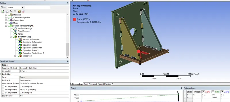
Setting up the analysis settings : Next the analysis settings are selected as shown below, the values of number of steps, automatic time-stepping are kept as default.
Large deflection is switched ON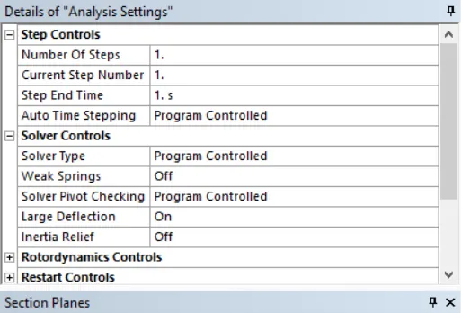
Output Parameters : The following parameters are selected for output from the simulation.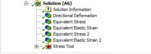
The stress tool is selected for the safety factor calculation on all the parts.
We select the following outputs :
Equivalent stress on all bodies
Equivalent strain on all bodies
Direction deformation in the direction of force application for small plate
Equivalent stress on the weld components
Equivalent strain on the ribs
Running the simulation :
Next we run the simulation. The simulation runs rather quickly in about 23.6 seconds.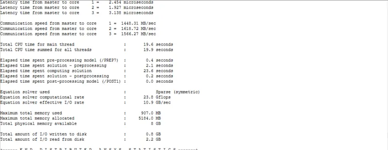
Post Processing :
We will evaluate the results for the different material assignments for the weld parts with the plates being in stainless steel.
1)Stainless Steel
2)Aluminium alloy(high strength, wrought)
3)Cast Bronze
Equivalent Stress :
Case 1)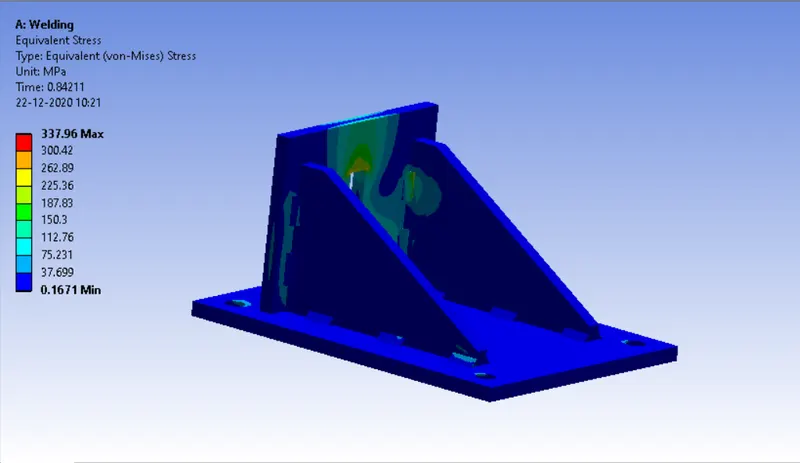
A maximum stress of 337.96 Mpa is experienced.
Case 2)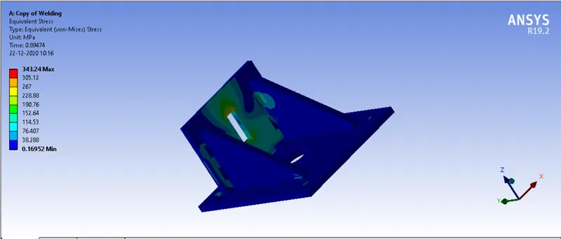
A maximum stress of 343.24 Mpa is experienced.
Case 3)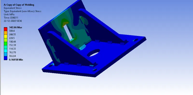
A maximum stress of 342.66 Mpa is experienced.
Equivalent elastic strain :
Case 1)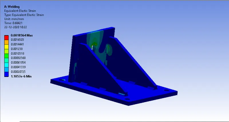
A maximum strain of 0.18% is experienced.
Case 2)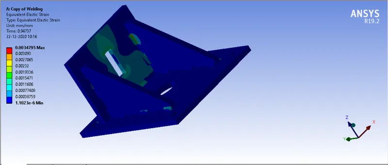
A maximum strain of 0.35% is experienced.
Case 3)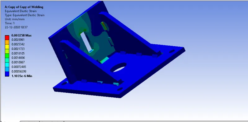
A maximum strain of 0.33% is experienced.
Directional deformation :
Case 1)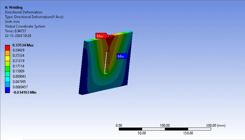
A directional deformation of 0.335mm is experienced by the small plate in the force direction.
Case 2)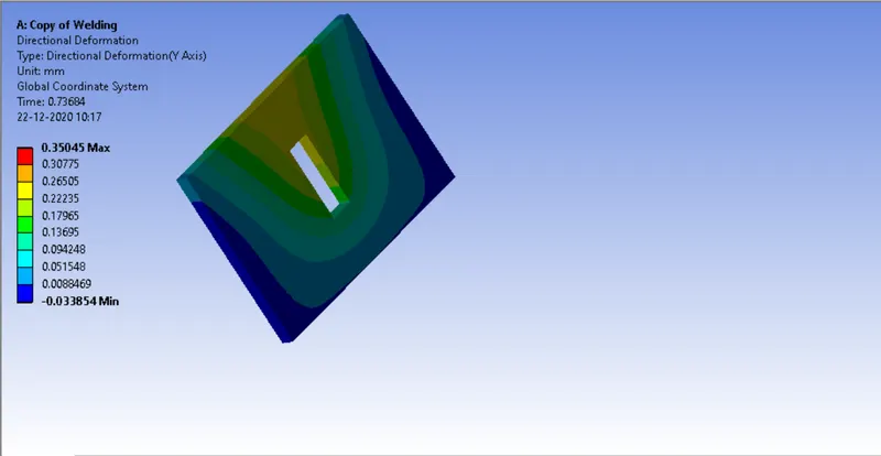
A directional deformation of 0.35mm is experienced by the small plate in the force direction.
Case 3)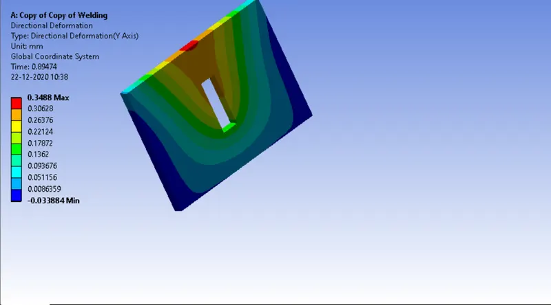
A directional deformation of 0.348mm is experienced by the small plate in the force direction.
Factor of safety :
Factor os safety is defined as the ultimate stress/working stress of the material. The lower the FOD of a material is, the more likely it is to fail. Various Industries use different FOS values for their components depending on the criticality of the component along with working life and other such factors.
Case 1)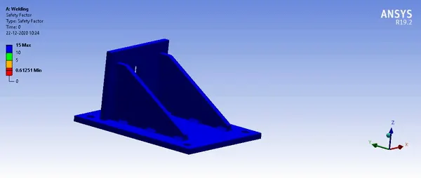
A minimum of 0.61 FOS occurs
Case 2)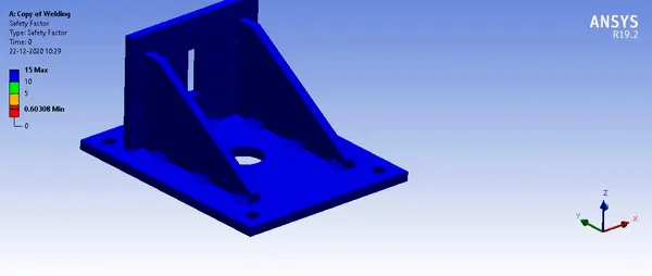
A minimum of 0.6 FOS occurs
Case 3)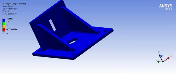
A minimum of 0.55 FOS occurs
Maximum weld stress :
The Stresses being experienced by the welds made of different materials are explained below according to material case study.
Case 1)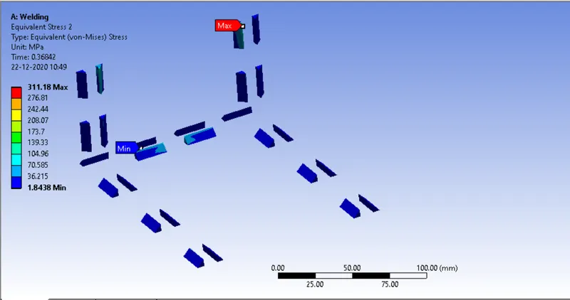
The maximum stress being experienced by the weld element is 311.18 Mpa as shown above.
Case 2)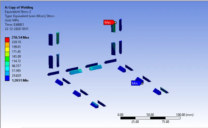
The maximum stress being experienced by the weld element is 256.54 Mpa as shown above.
Case 3)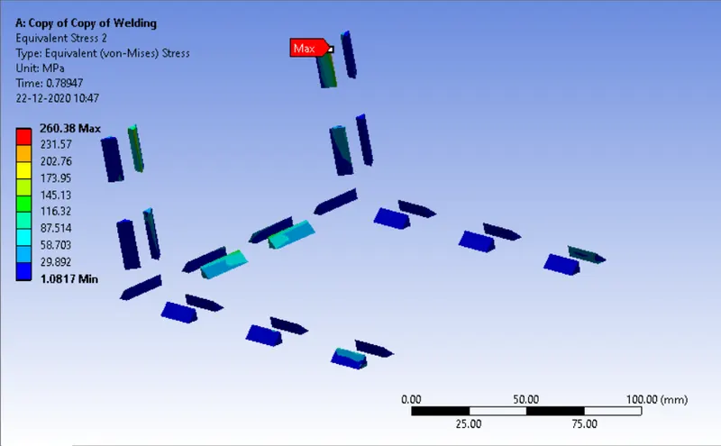
The maximum stress being experienced by the weld element is 260.38 Mpa as shown above.
As we can see above in all the 3 cases, the weld element experiencing the highest stress remains the same regardless of the weld material. This is due to the geometry of the component and the location of the force being applied.
The consolidated results have been given below in tabular format :
| Equivalent stress (max) | Equivalent strain (max) | Directional Deformation(max) | FOS (lowest) | |
| Stainless Steel | 337.96 Mpa | 0.18% | 0.335mm | 0.61 |
| Aluminium alloy(high strength, wrought) | 343.24 Mpa | 0.35% | 0.35mm | 0.6 |
| Cast Bronze | 342.66 Mpa | 0.33% | 0.348mm | 0.55 |
Hence we can conclude that Stainless steel offers the most strength in the welds whereas Aluminium alloy offers the least in the given load conditions. However Bronze exhibits the lowest factor of safety. So depending on our requirements we can choose the appropriate weld material.
Conclusion :
Hence the simulations have been successfully conducted with the different weld materials and the desired output has been obtained.
Result :
File has been attached below.