Week 3 Sheet metal Bending challenge
Objective :
To perform the simulation of the given sheet metal bending using the different materials for the sheet metal and observing the changes in behaviour with change in friction coefficient and mesh size.
Procedure :
Setting up the simulation
To set up the simulation, first we need to import all the required material cards such as Aluminium Alloy 1199 ,Copper Alloy NL and Magnesium Alloy NL for the sheet metal and structural steel for the die & punch.
The above materials can be found in the General non-linear materials library.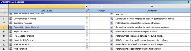
Structural Steel for the die and punch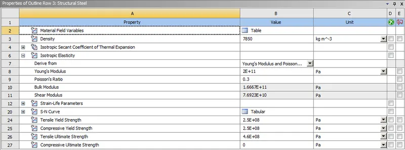
Aluminium Alloy 1199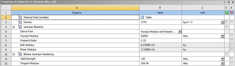
The material properties of Aluminium Alloy NL are modified to the following values of Young's modulus, Yield strength & Tangent Modulus respectively.
Copper Alloy NL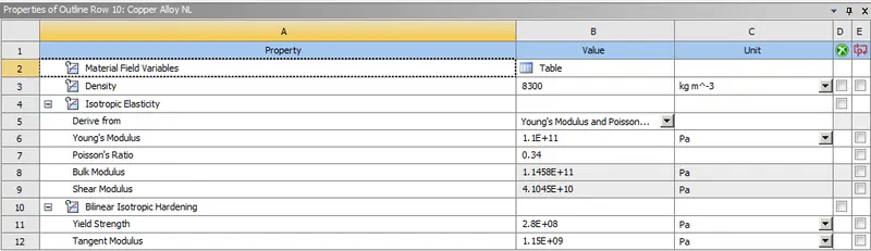
Magnesium Alloy NL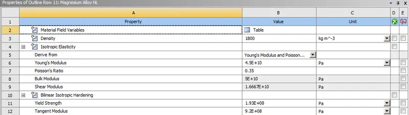
Importing geometry :
Next we import the geometry which the CAD file of the die. pinch & sheet metal setup which has been provided.
Material defintion : 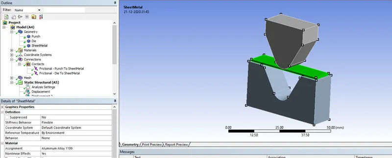
The material Aluminium Alloy is assigned to the gears and structural steel for the die & punch for the first case.
Then we will open Ansys mechanical to set up the rest of the simulation.
To set up the contact we go to connections-->contacts and open the contact card.
We will create 2 contacts,
1)Between the punch and the sheet
2)Between the sheet and the die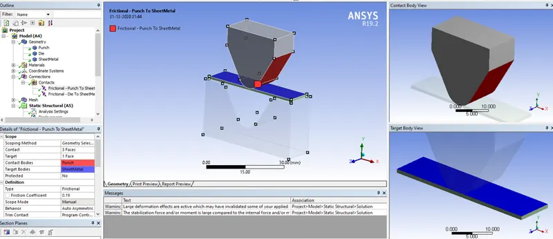
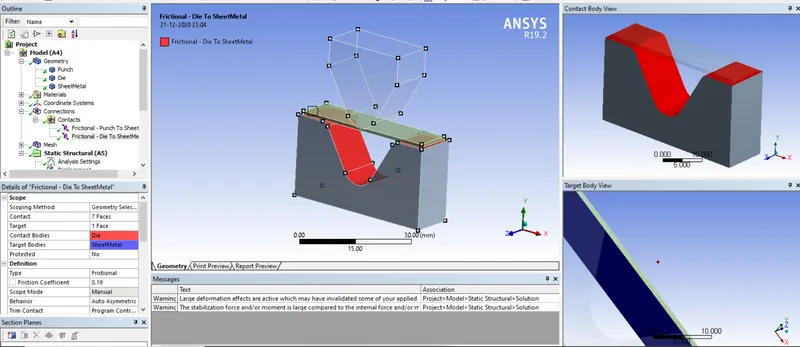
Type = frictional
Coefficient of friction = 0.1
Formulation = Augmented Lagrange
Normal stiffness factor = 0.1
Interface treatment = Add Offset, ramped effects
Next we mesh the components.
A body sizing of 4mm in applied on the punch and die as shown below.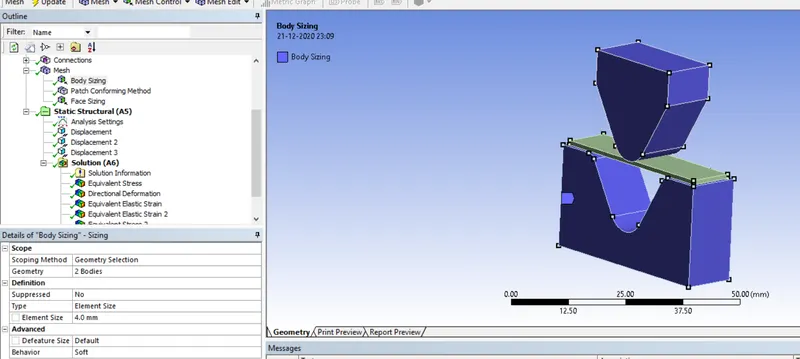
A meshing method of tetrahedrons is applied to the sheet metal as shown below.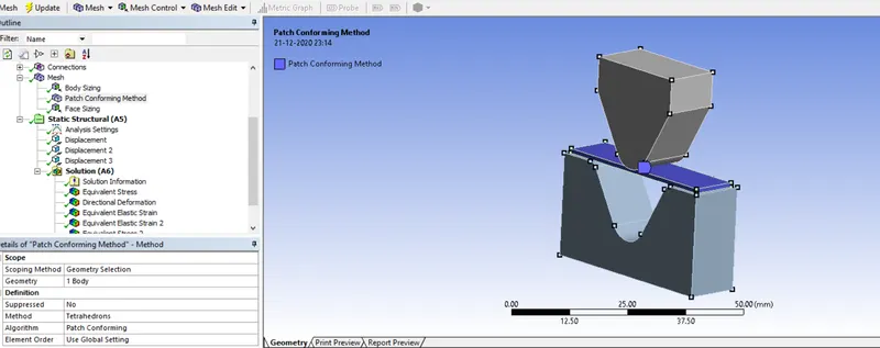
A face sizing of 1mm is applied to the surfaces in contact (i.e between the die and the sheet and the sheet and the punch)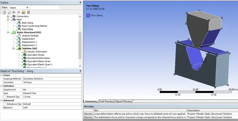
Creation of loads: Next we assign the displacement to the punch & the die as shown below.
The top faces of the punch are given a motion in the negative y-direction as shown. The motion is uptill the 8th step and then it retracts upwards.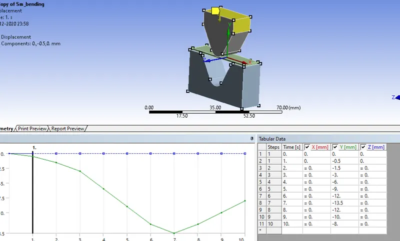
Similarly the die is inputted a data in the last 2 steps to retract it from the sheet as shown below after the punch begins retracting.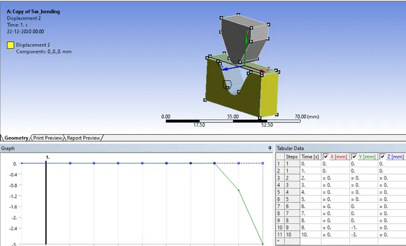
Next we provide a motion to the sheet which restricts its motion in the z-axis and allows it to move in the x,y axes.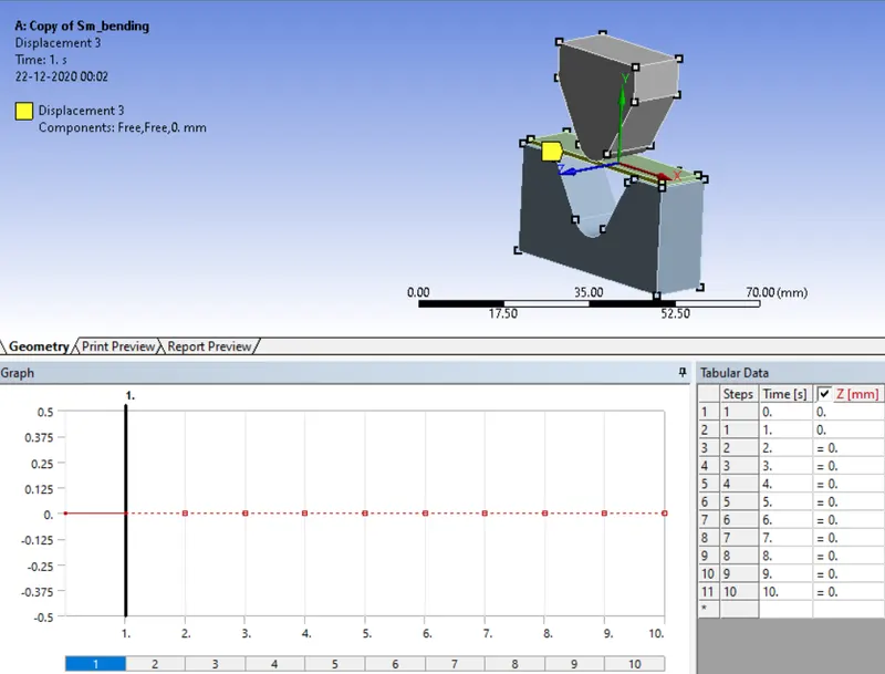
Setting up the analysis settings : Next the analysis settings are selected as shown below, inputting the values of number of steps as 10.
Solver type = direct
Large deflection = on
Stabilization = constant
Constant = 0.1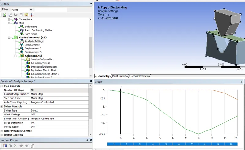
Output Parameters : The following parameters are selected for output from the simulation.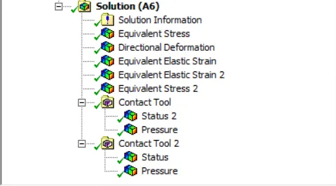
The equivalent stress & equivalent strain are taken for just the sheet metal as well as all the bodies.
Then we choose the contact tool, one for each contact interface, and request the pressure for the output as well.
Running the simulation :
Next we run the simulation. The simulation takes about 10 minutes to run as we can see from the runtime below.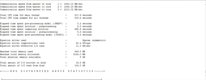
Post-processing :
Case 1)
The simulation is run for all the 3 materials by changing material assignment and re-running it.
We will evaluate the results looking by looking at the behaviour in all the different materials.
1)Aluminium Alloy 1199
2)Copper Alloy NL
3)Magnesium Alloy NL
Equivalent Stress :
Aluminium Alloy 1199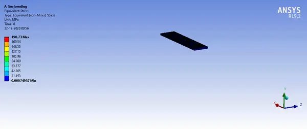
A peak stress of 190.73 Mpa is obtained is obtained at the middle of the sheet metal plate as shown above for aluminium alloy.
Copper Alloy NL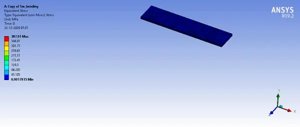
A peak stress of 387.91 Mpa is obtained is obtained at the middle of the sheet metal plate as shown above for copper alloy.
Magnesium Alloy NL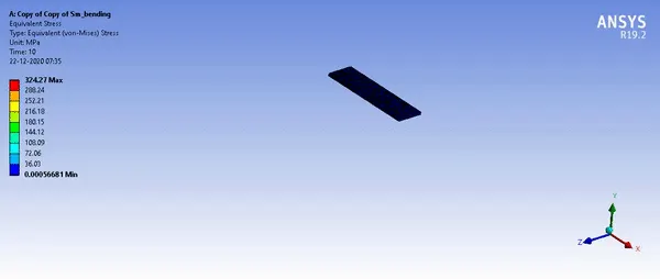
A peak stress of 324.27 Mpa is obtained is obtained at the middle of the sheet metal plate as shown above for magnesium alloy.
Equivalent Strain :
Aluminium Alloy 1199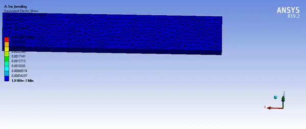
A peak strain of 0.3% occurs in the sheet in equivalent elastic Von-mises strain for aluminium alloy.
Copper Alloy NL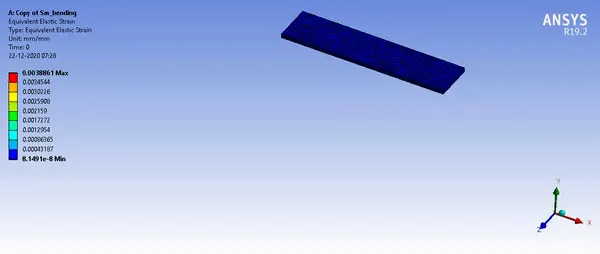
A peak strain of 0.38% occurs in the sheet in equivalent elastic Von-mises strain for copper alloy.
Magnesium Alloy NL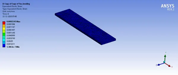
A peak strain of 0.92% occurs in the sheet in equivalent elastic Von-mises strain for magnesium alloy.
Directional Deformation :
Aluminium Alloy 1199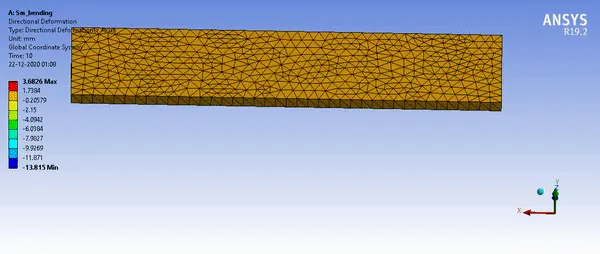
A maximum directional deformation in the y-direction (downward) of 3.6826 mm occurs at the edges of the plate for Aluminium alloy.
Copper Alloy NL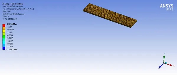
A maximum directional deformation in the y-direction (downward) of 3.70 mm occurs at the edges of the plate for copper alloy.
Magnesium Alloy NL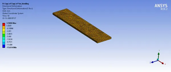
A maximum directional deformation in the y-direction (downward) of 3.76 mm occurs at the edges of the plate for magnesium alloy.
Contact pressure distribution :
The contact pressure distribution remains the same regardless of the material of the sheet metal.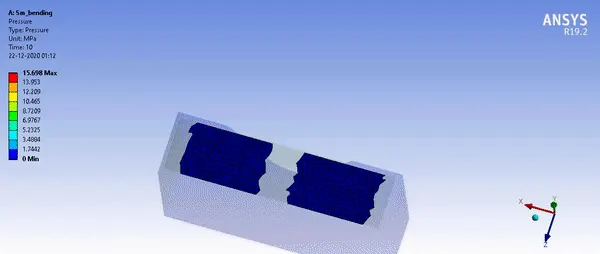
As we can see the pressure distribution moves from the point of contact which is in the centre to the ends of the plate. This indicates that the contact occurs properly between die and the sheet.
Below we can see the pressure distribution on the sheet caused by the impact of the die.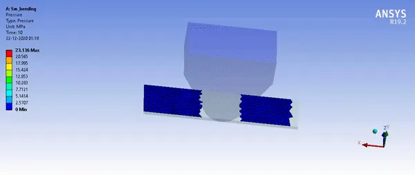
Case 2)
Next we will change the coefficient of friction for the contacts and see the difference in the above mentioned parameters for aluminium alloy. 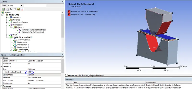
Equivalent stress : 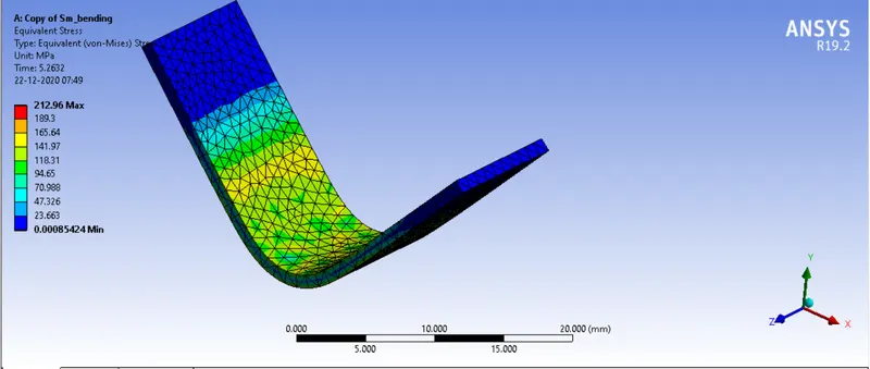
A peak stress of 212.96 Mpa is obtained on the sheet
Equivalent strain : 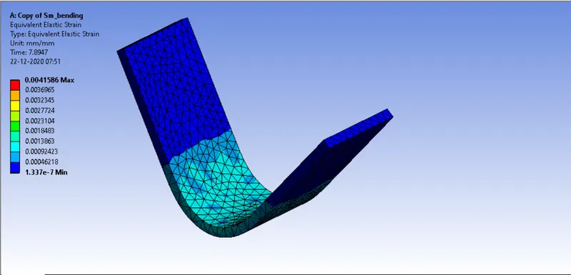
A peak strain of 0.42% is obtained on the sheet.
Directional Deformation : 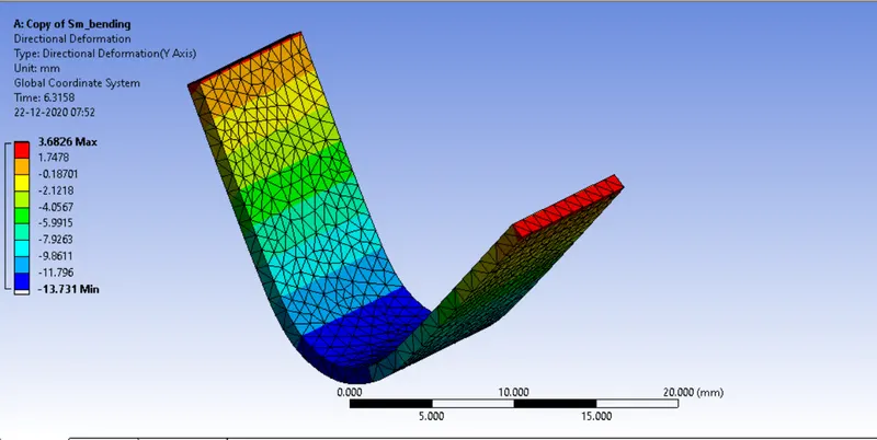
A peak deformation of 3.6826 mm is obtained on the sheet.
Contact pressure :
The contact pressure increases due to an increase in the coefficient of friction from the previous case of Aluminium with a coefficient of friction of 0.1
Contact pressure between punch and sheet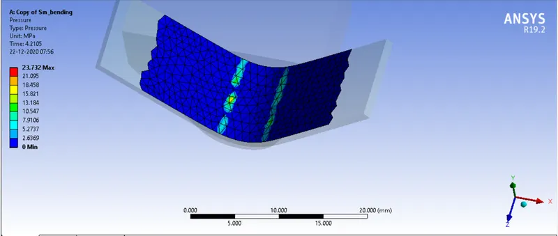
Contact pressure between die and sheet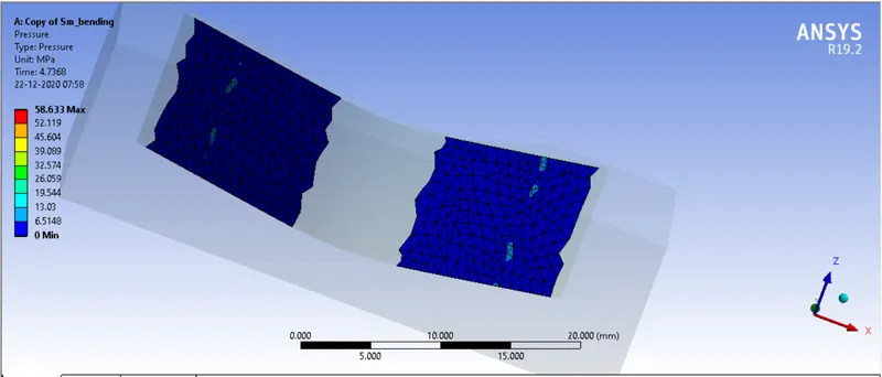
Case 3)
Next we will refine the mesh a bit and see the change in the results, if any.
Equivalent Stress : 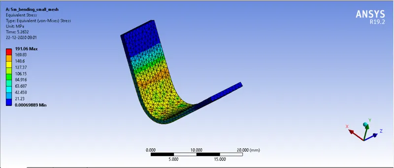
A maximum stress of 191.06 Mpa is obtained at the centre of the sheet metal.
Equivalent Strain : 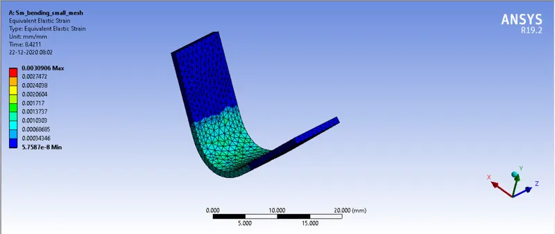
A maximum strain of 0.309% is obtained at the centre if the sheet.
Directional deformation : 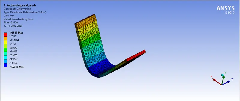
A maximum deformation of 3.68mm is obtained at the ends of the sheet.
The tabulated results for all 3 cases have been given below :
Case 1)
| Equivalent stress (max) | Equivalent strain (max) | Directional deformation (max) | |
| Alumium Alloy 1199 | 190.73 Mpa | 0.31% | 3.6826 mm |
| Copper Alloy | 387.91 Mpa | 0.39% | 3.70 mm |
| Magnesium Alloy | 324.27 Mpa | 0.92% | 3.76 mm |
Case 2)
| Equivalent stress (max) | Equivalent strain (max) | Directional deformation (max) | Contact pressure (sheet & punch) | Contact pressure (die & sheet) | |
| Alumium Alloy 1199 (Coeff = 0.1) | 190.73 Mpa | 0.31% | 3.6826 mm | 23.136 Mpa | 15. 698 Mpa |
| Alumium Alloy 1199 (Coeff = 0.19) | 212.96 Mpa | 0.42% | 3.6826 mm | 23.732 Mpa | 58.633 Mpa |
Case 3)
| Alumium Alloy 1199 (Mesh size) | Equivalent stress (max) | Equivalent strain (max) | Directional deformation (max) |
| 4mm | 190.73 Mpa | 0.31% | 3.6826 mm |
| 2.5mm | 191.06 Mpa | 0.31% | 3.68mm |
Conclusion :
Hence the various case scenarios for the sheet metal bending simulation have been performed and the desired output has been obtained.
Result :
The files have been arranged in case wise folders.
Sheet Metal Bending