Bird Strike - Project - 2
Objective : To study the effect of bird strike on a plane engine.
Procedure :
Setting up the simulation
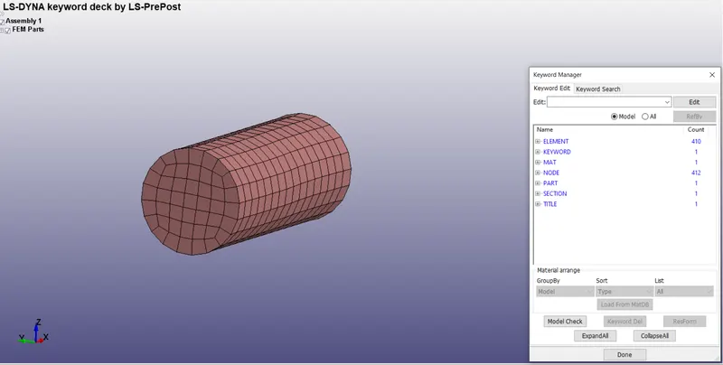
First we will set up the different parts of the engine into different .k files as shown below.
Bird file
Blades file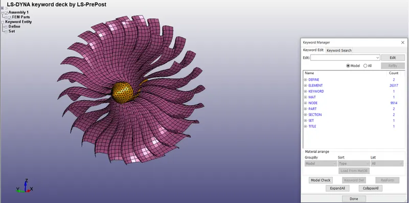
Casing file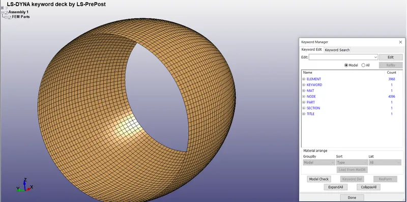
All these files contain the material properties, section and are assigned to the part
Creating the main file :
Next we include all these files into a main file. The main file just contains of all the include files and nothing else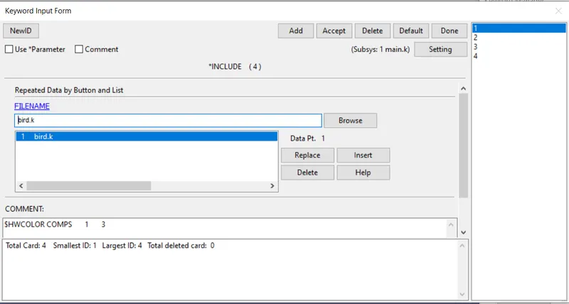
The numbering convention as given below is followed for certain entities as it is a multi-include file and to ensure uniformity
| Numbering convention | ||||
| Part IDs | Material IDs | Section IDs | Velocity IDs | Contact IDs |
| 1000+ | 2000+ | 10+ | 50+ | 100+ |
The following numbering system is used for the nodes, shells and solid elems of the different components.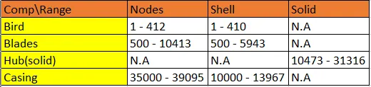
Creating physics file :
Now that we have included all the files into the main file we can create the physics file with reference to the included parts.
Velocity cards
To assign rotation to the rotor, we will create a initial velocity generation card like this. A rotational velocity of 0.4 is assigned along the x-axis and the part sed ID consisting of hub and blades is selected.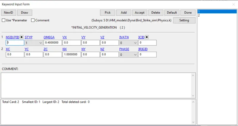
To assign translation to the bird model we will create this card and assign a velocity of 10.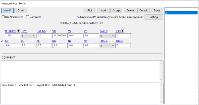
Contact definition :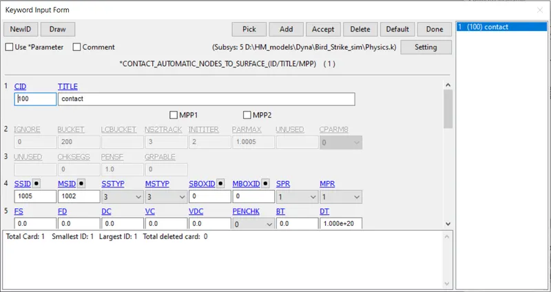
This contact is created between the blades of the engine and the bird object.
Control Parameters :
Next we create the timestep control parameters as shown below.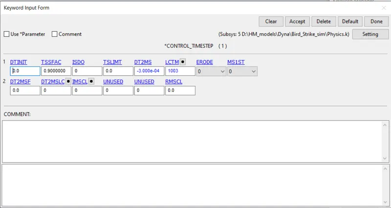
A curve for LCTM is used to ensure the timestep does not go above 0.1 ms.
This curve is used for the LCTM curve to limit maximum timestep.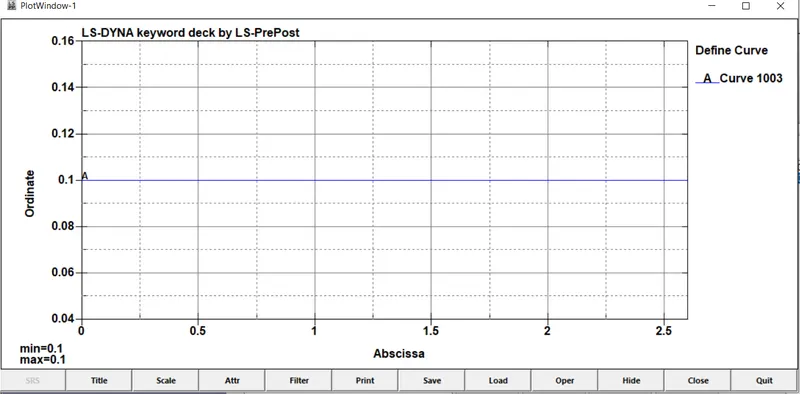
For dt2ms value the optimum value is found using trial and error method to get the best compromise if reduced time and %added mass.
| dt2ms | simulation time | % mass increase |
| 1.00E-03 | error | 150% |
| 5.00E-04 | 02:21 | 56% |
| 4.00E-04 | 04:40 | 11.60% |
| 3.00E-04 | 07:07 | 3.90% |
Hence the lower most value is selected for dt2ms as it gives the best compromise between both.
Termination : 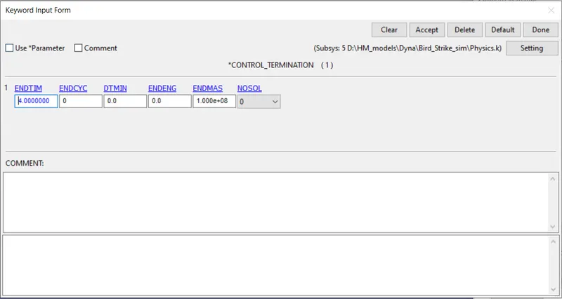
A termination of 4ms is chosen for the simulation
Database Parameters : 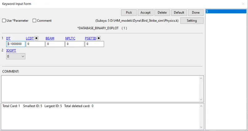
The binary d3plot is chosen with the following timestep.
The following cards are chosen in the ascii plot GLSTAT, MATSUM, NSFORC, RCFORC with the timestep of 0.1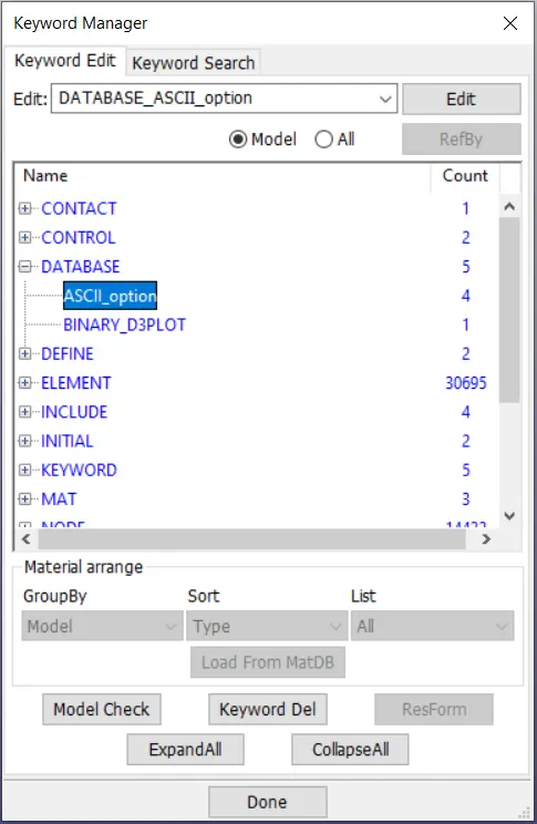
Test simulation :
Before running the actual simulation, a dummy simulation is created with all the different components in the same file and no need of using include files.
It is in this simulation that all the errors are understood and debugged before creation of the main file. A log has been created about the various errors encountered and the various fixes for it.
| Issues faced | Solution | Improvement |
| Rotational velocity not getting applied using initial velocity/prescribed motion | Use initial velocity generation card to both blade and hub | Velocity successfully applied to rotating parts |
| Unusual deformation of solid parts during motion (rotation) | Use section type 13 for solid | No unusual deformation noted during the run |
| Minimum timestep reached in solid element during run | Use mass scaling in timestep card | Simulation runs properly |
| Simulation error caused by elements faling | Using control timestep card with dt2ms value | Simulation runs properly |
The practice simulation run file is given below.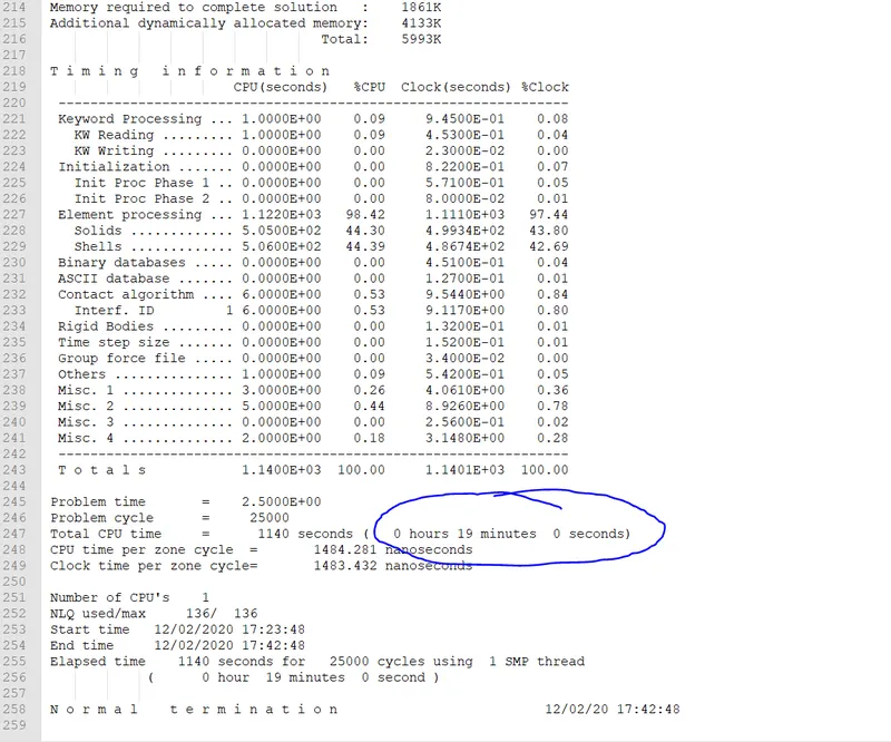
As we can see the run time for this simulation is 19 minutes.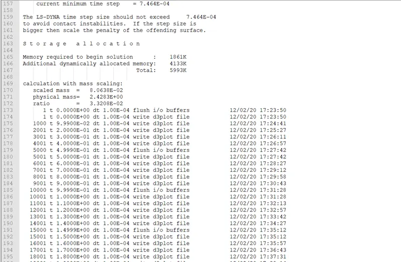
Also the added mass is of the order of just 3.3% This is where we get the approximate dt2ms value to be used in the actual simulation.
Running the simulation :
Now we will run the actual simulation using the timestep, termination time and other parameters which were found to be optimum in the test run of the bird strike simulation.
Simulation mechanics
The simulation starts with the blades rotating about their axis and the bird model moving toward the blades.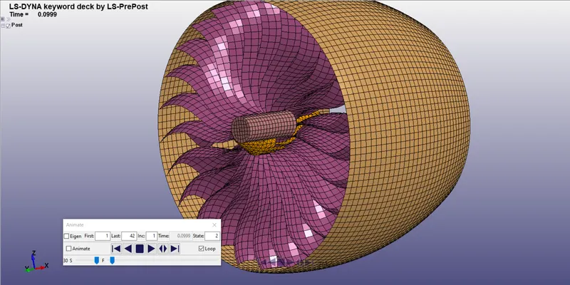
We can see that around 2.2 ms the bird makes contact with the blades of the engine.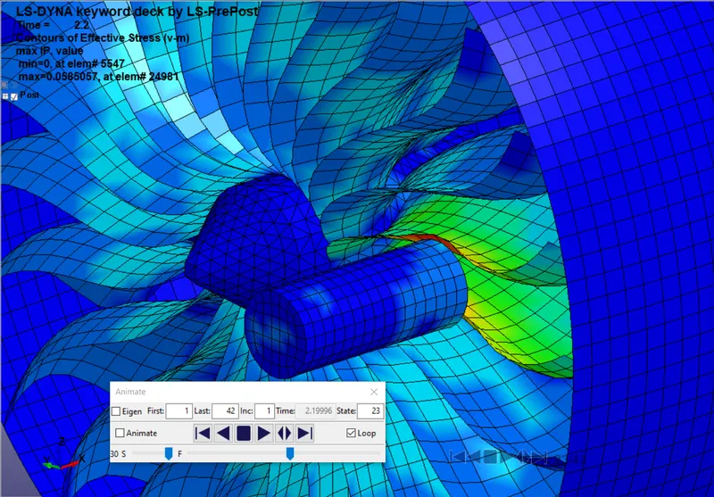
This causes the blades to deform slightly due to the material properties of bird and blades, as well as the velocities of the blades and the bird.
After making contact the bird model deflects off and falls down as shown below in the final frames.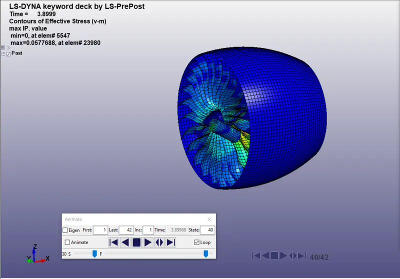
Stress Distribution:
We can see the stress distribution below. The bird on making contact induces a stress in a couple of blades with which it makes contact with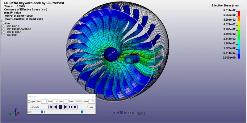
Peak stress is obtained of around 0.066 Gpa at element 3909.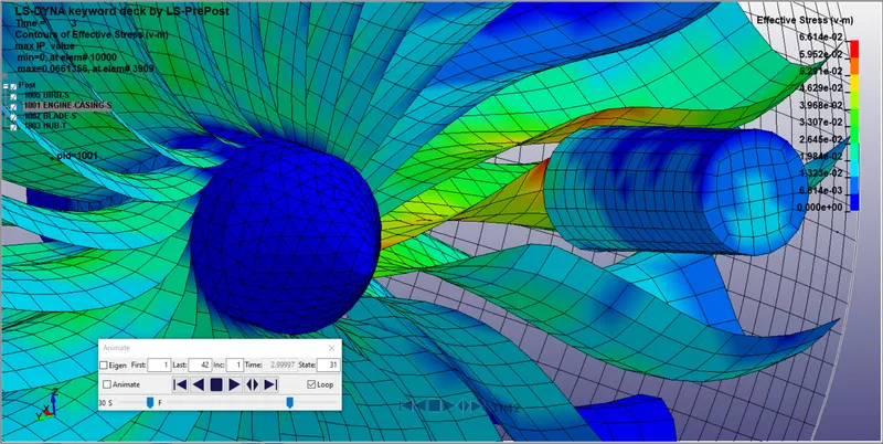
Strain : 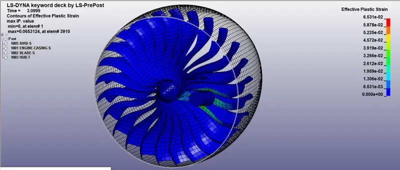
Maximum strain of 6.5% occurs on the blades of the engine.
Energy plots :
As we can see below the loss in kinetic energy is proportional to the gain in internal energy. 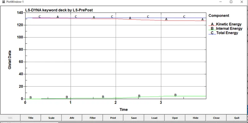
The total energy in the system reduces slightly as we can see in the graph above.
Timestep :
The timestep remains constant and is governed by dt2ms and tssfac giving it a constant value as shown below.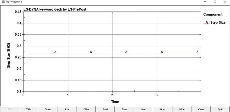
Interface Forces : 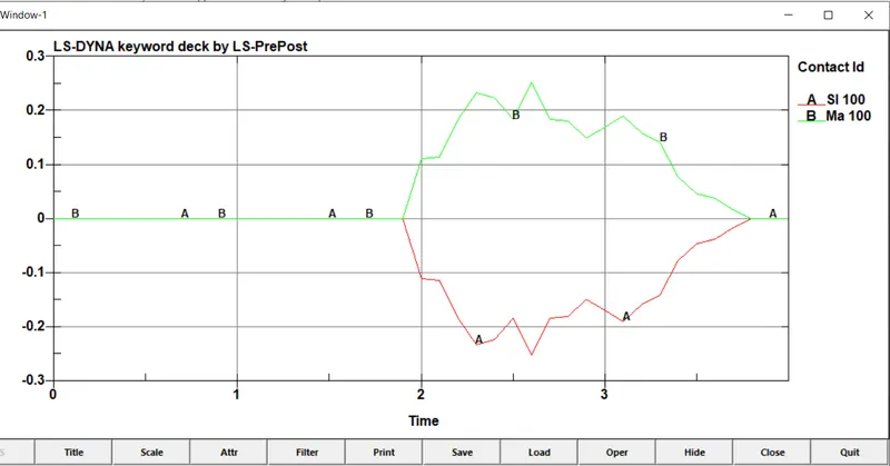
By selecting the SPR and MPR option in the contact definition we can get the output from the master and slave components in the form of interface forces as shown above.
The Slave force is in the opposite direction of the master force.
Conslusion : Hence the simulation for birdstrike on an airplane negine has been succesfully run with the desired output.
Result :
BirdStrike_simfiles
Birdstrike_logs