week-11 Joint creation and Demonstration
Objective : To create the given joints on FE models and check their movement by running the simulation.
Procedure :
Setting up the simulations :
First we will model the joints on
Deformable bodies
Spherical joint
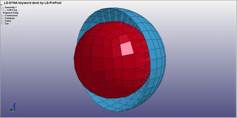
Create a solid ball and socket assembly in LS-DYNA as shown below.
Create the following material card for deformable bodies, The material system being used in gm,mm,ms.
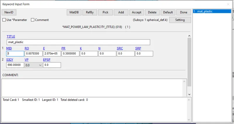
Assign the material and section IDs to both parts.
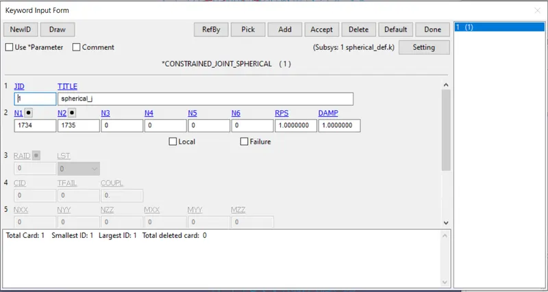
Create 2 nodes at the centre of the sphere for joint creation. (1734 & 1735)
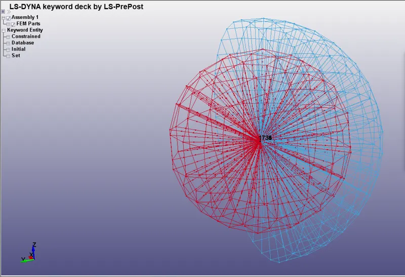
Define the spherical joint using these 2 nodes.
Now we will link these 2 nodes to the defomrable bodies using Constrained_nodal_bodies option.
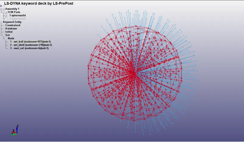
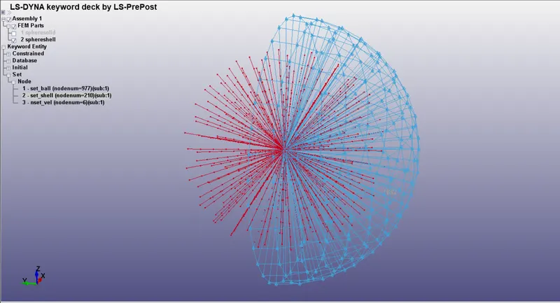
We will create 2 nodesets.
- One with node 1734 and nodes of inner ball.
- One with node 1735 and nodes of outer socket.
Now we will assign velocity to the nodes of the shell to check for relative motion between both and set up the simulation.
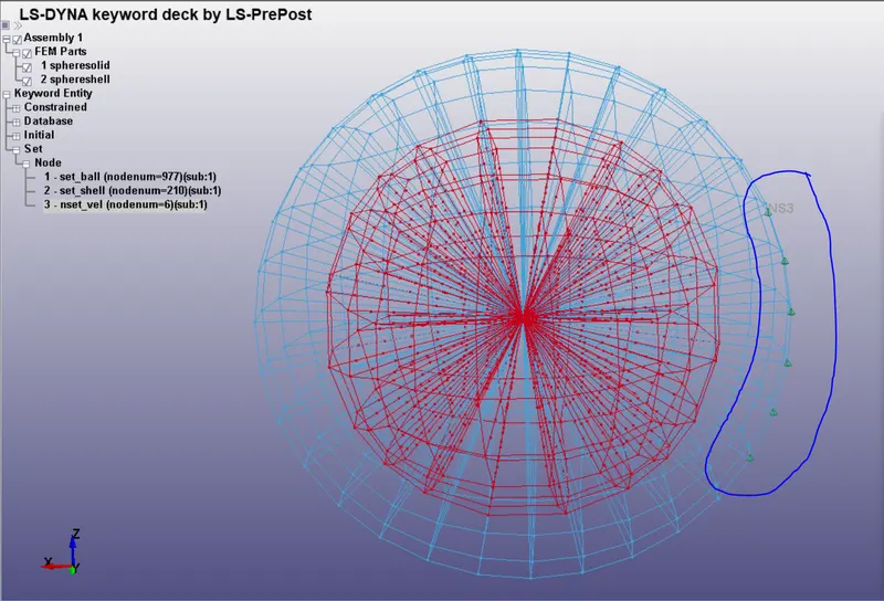
A velocity is applied to these nodes in the negative y-direction of 10 mm/ms.
The simulation is run for 10 ms.
Cylindrical Joint :
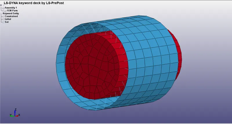
Create a cylinder and sleeve using shape mesher in LS-Dyna as shown above.
Create the following material card for deformable bodies, The material system being used in gm,mm,ms.
Assign the material and section IDs to both parts.
Create 2 pairs of nodes along the centerline of the sleeve and cylinder as shown below. (634, 635, 847, 846)
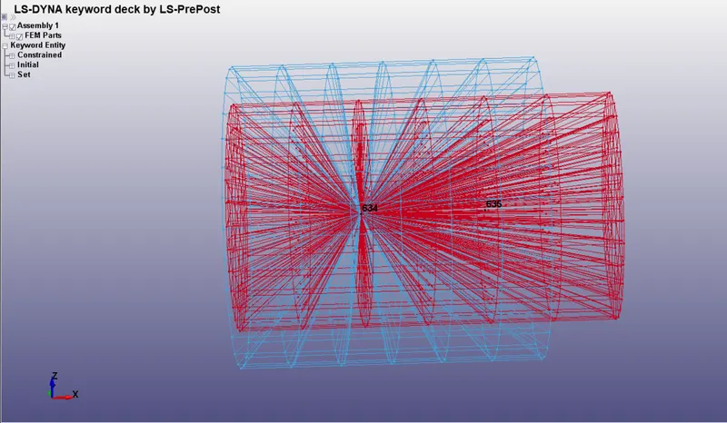
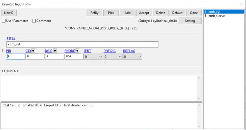
These 2 nodes are linked to the inner cylinder nodes using constrained nodal rigid bodies.
Next create a pair of nodes for the outer sleeve (847 & 846)
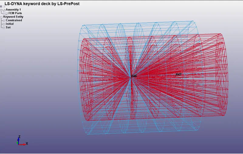
These 2 nodes are linked to the outer sleeve nodes using constrained nodal rigid bodies.
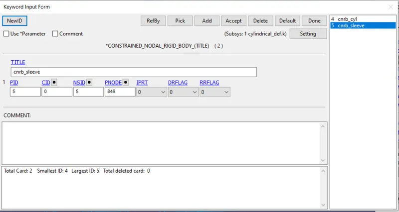
Next we will apply velocity to a set of nodes on the sleeve.
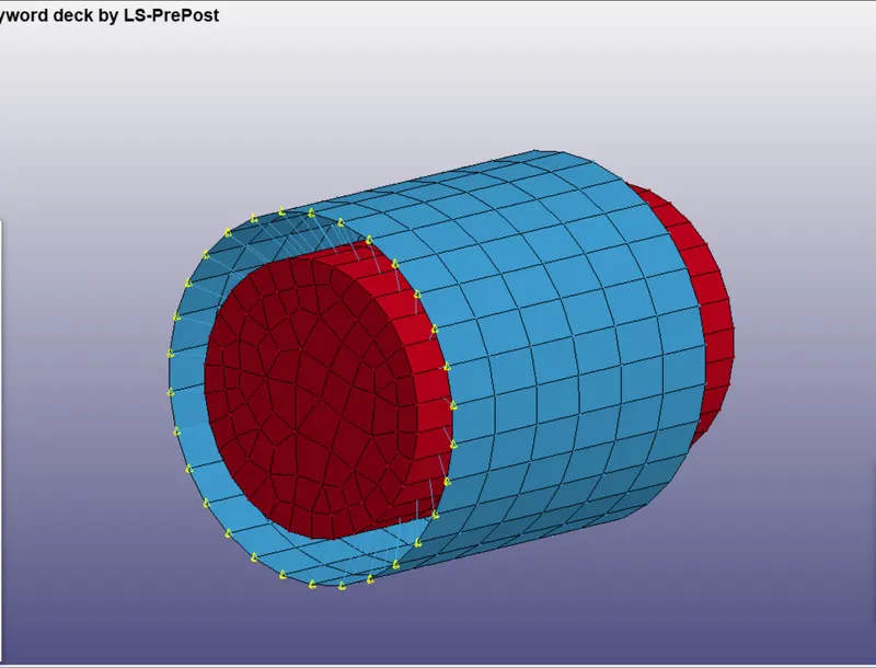
A velocity of 10 mm/ms is applied in the x-direction.
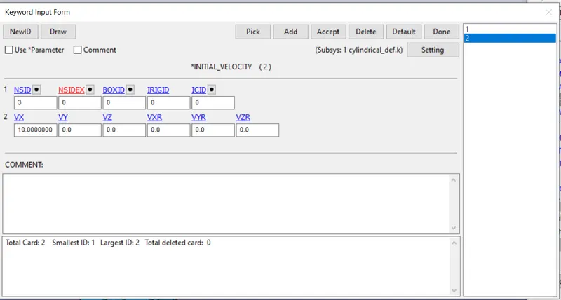
Along with translational, a rotational velocity is applied as well to these nodes as shown below to show the rotation allowed along the axis of the sleeve/cylinder assembly in the case of cylindrical joint.
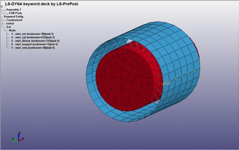
The same termination time of 10 ms is used.
Translational Joint :
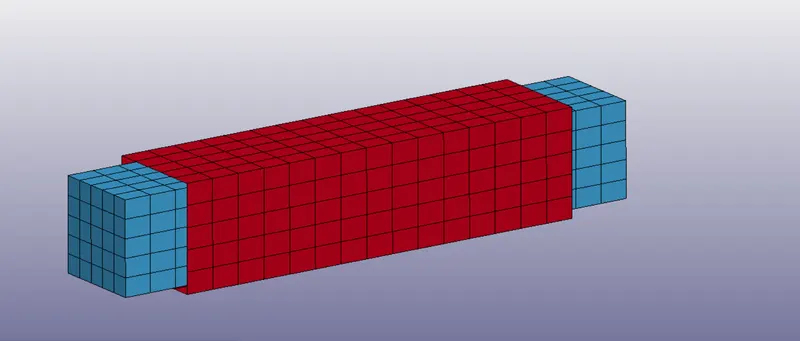
Create a square section beam and a sleeve for it as shown below.
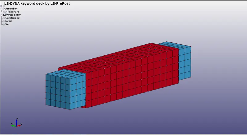
Create the following material card for deformable bodies, The material system being used in gm,mm,ms.
Assign the material and section IDs to both parts.
Create a pair of nodes for the inner beam, 2 along the centerline and one off the axis for locking the rotational motion (327, 328 & 1089)
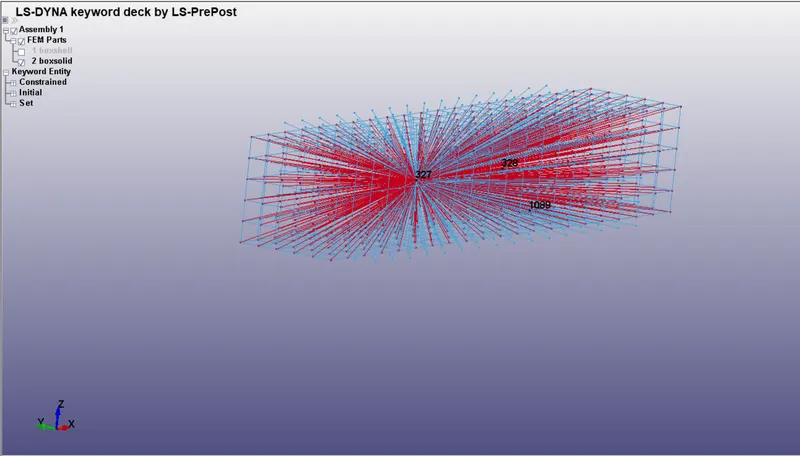
These 3 nodes are linked to the inner beam nodes using constrained nodal rigid bodies.
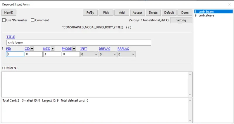
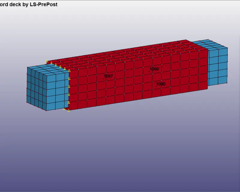
Next create the same set of nodes for the outer sleeve (1087, 1088 & 1090)
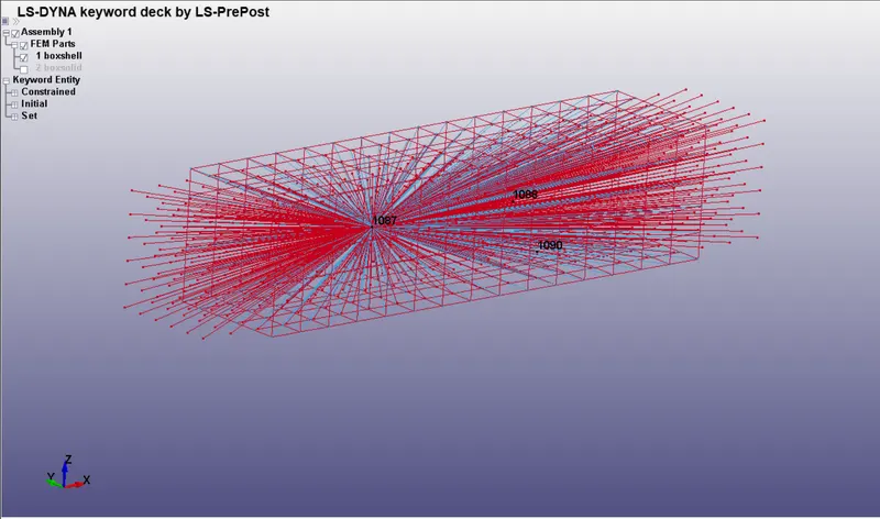
These 3 nodes are linked to the outer sleeve nodes using constrained nodal rigid bodies.
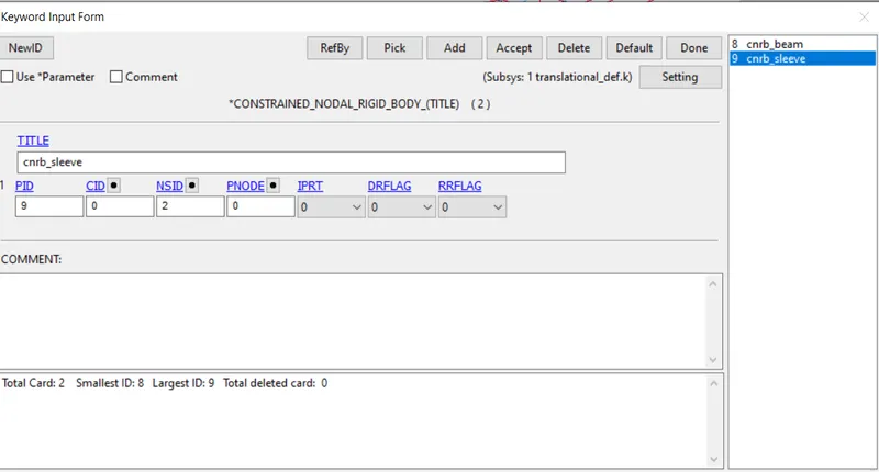
Next we will apply velocity to a set of nodes on the sleeve.
A velocity of 10 mm/ms is applied in the x-direction.
Along with translational, a rotational velocity is applied as well to these nodes as shown below to show the rotation allowed along the axis of the sleeve/cylinder assembly in the case of cylindrical joint.
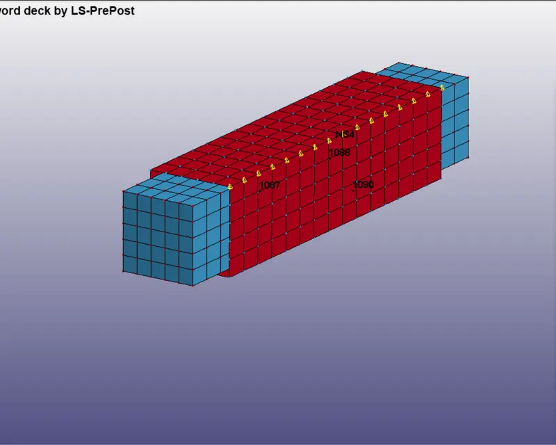
The velocity is applied to y and z directions so that the resultant gives a tangential velocity of 50 m/s.
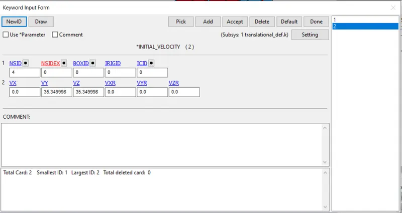
The same termination time of 10 ms is used.
Revolute joint :
Create 2 separate beam type sections as shown below using shape mesher in LS-Dyna as shown below.
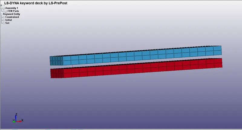
Create the following material card for deformable bodies, The material system being used in gm,mm,ms.
Assign the material and section IDs to both parts.
Create 2 nodes along the centerline the axis of rotation for the lower red beam as shown below. (757, 759)
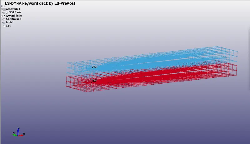
These 2 nodes are linked to the inner beam nodes using constrained nodal rigid bodies.
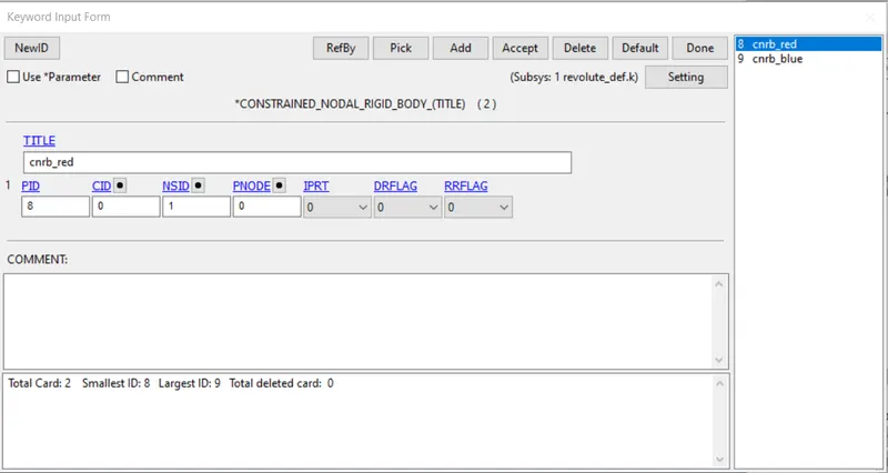
Next create the same set of nodes for the blue beam (758, 760)
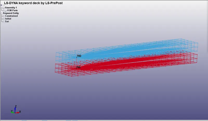
These 2 nodes are linked to the outer sleeve nodes using constrained nodal rigid bodies.
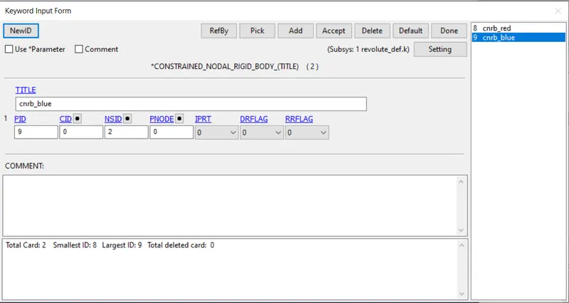
Next we will apply velocity to a set of nodes on both the beams in the opposing directions as shown below.
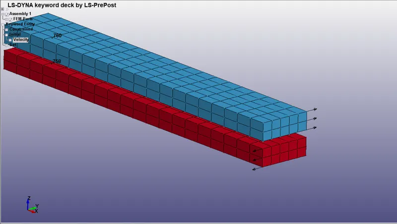
A velocity of 30 mm/ms is applied along the y-axis in opposing directions for both the upper and lower beams.
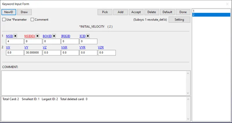
The same termination time of 10 ms is used.
First we will model the joints on
Rigid bodies
The process for modelling the joints on rigid bodies is exactly the same , the only difference is changing the material card and in place of using CONSTRAINED_NODAL_RIGID_BODIES, the card CONSTRAINED_EXTRA_NODES is used.
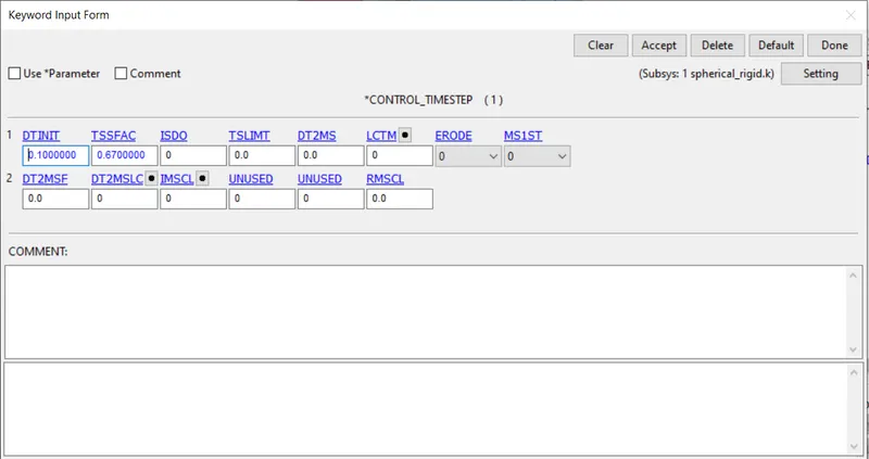
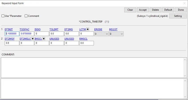
We will also use a control timestep card to quit the simulation from terminating too quickly and giving us innacurate results. In the following section we will only deal with these changes and not the whole simulation.
Spherical joint
Create the following material card for Rigid bodies, The material system being used in gm,mm,ms.
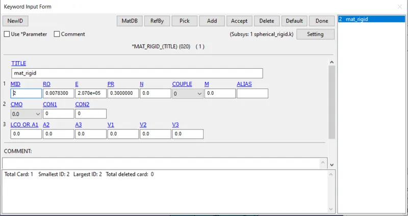
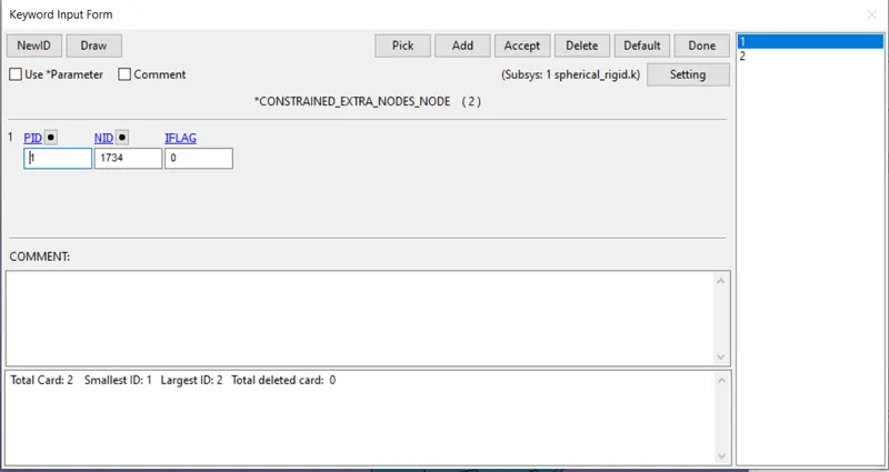
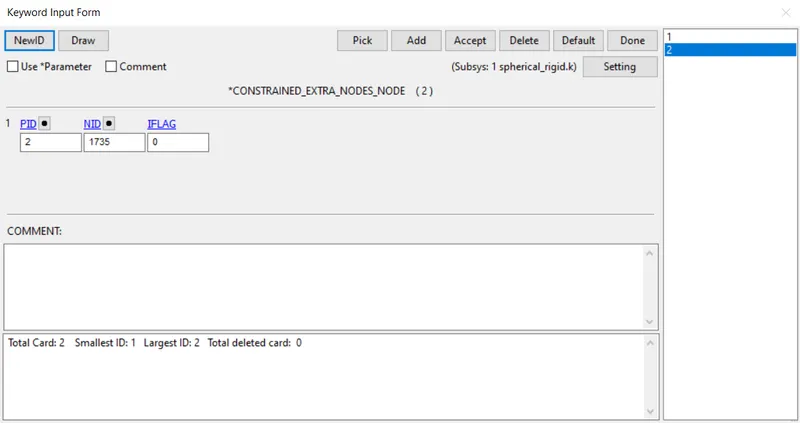
Now we will link these 2 nodes to the deformable bodies using Constrained_nodes_extra option.
The node 1734 are is linked to the ball using this option.
The node 1735 are is linked to the socket using this option.
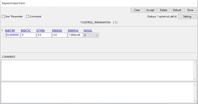
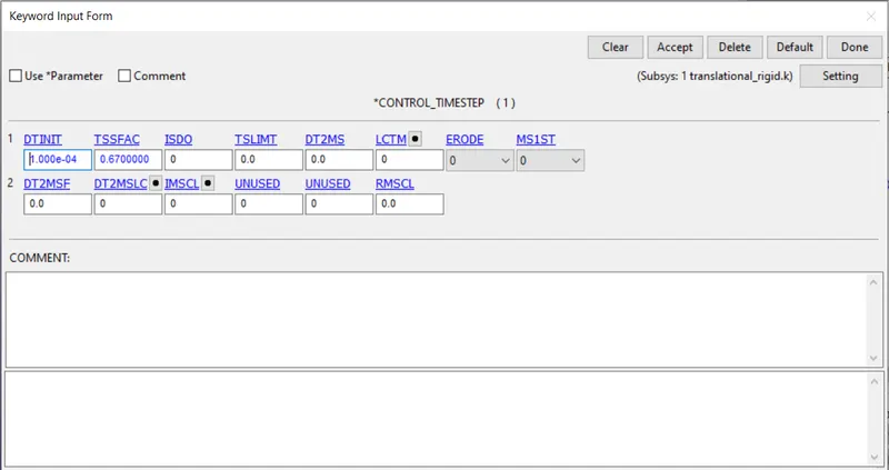
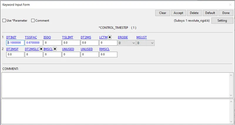
A control timestep card is used to control the timestep to get accurate results by preventing the simulation from ending too quickly due to use of rigid body in the material card thereby drastically reducing the number of calculations to be done.
Cylindrical Joint :
The material card for rigids is the same as used above.
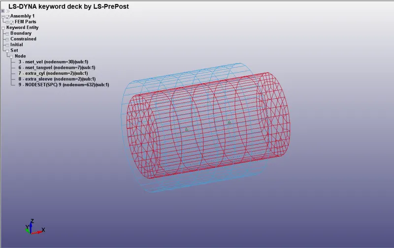
Create 2 pairs of nodes along the centerline of the sleeve and cylinder as shown below. (634, 635, 847, 846)
A nodeset is created to be linked to the cylinder and to the sleeve respectively (extra_cyl and extra_sleeve)
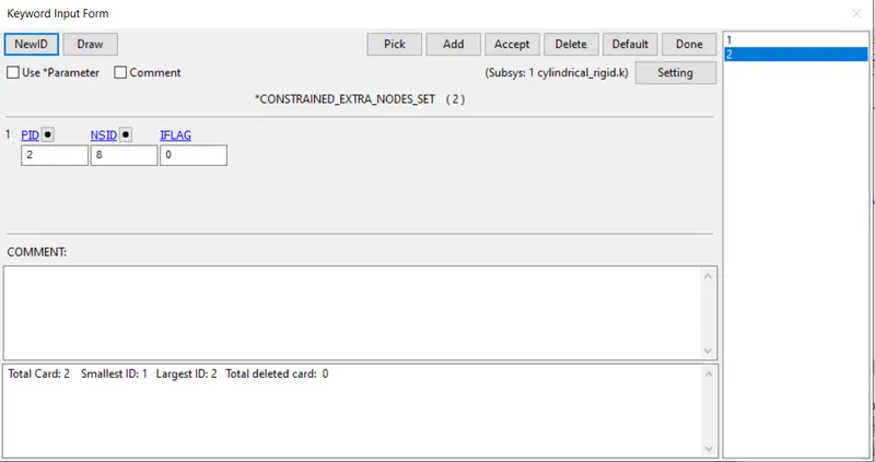
These 2 nodes are linked to the inner cylinder nodes using constrained nodes extra.
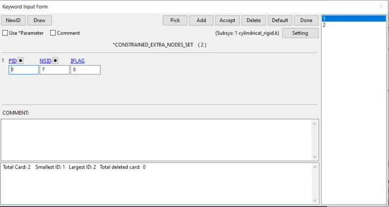
These 2 nodes are linked to the outer sleeve nodes using constrained nodes extra.
Control timestep card is used as shown below.
Translational Joint :
The material card for rigids is the same as used above.
Create 3 pairs of nodes along the centerline and one along an offset of the sleeve and cylinder as shown below. (327,328,1087,1088,1089,1090)
A nodeset is created to be linked to the beam and to the sleeve respectively (extra_beam and extra_sleeve)
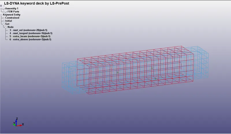
These 2 nodes are linked to the inner beam nodes using constrained nodes extra.
These 2 nodes are linked to the outer sleeve nodes using constrained nodes extra.
Control timestep card is used as shown below.
Revolute joint :
The material card for rigids is the same as used above.
Create 2 pairs of nodes along the axis of rotation of the revolute joints(757,759,758,760)
A nodeset is created to be linked to the red beam and to the blue beam respectively (extra_red and extra_blue)
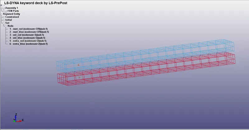
These 2 nodes are linked to the inner beam nodes using constrained nodes extra.
These 2 nodes are linked to the outer sleeve nodes using constrained nodes extra.
Control timestep card is used as shown below.
Running the simulations :
We have found that the mechanism of the simulations using the above 4 joints are the same whether we use rigid bodies or deformable bodies. So we will just look at the results below for the 4 joints as shown below.
Spherical Joint :
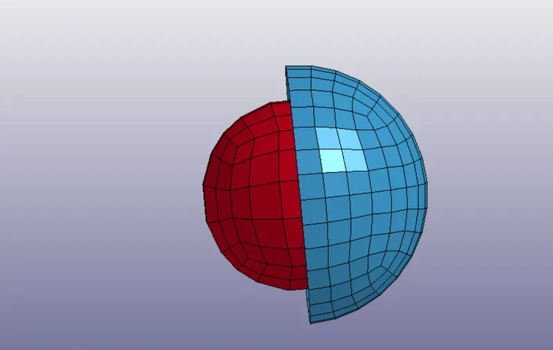
First frame
Last frame
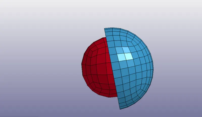
As we can see the outer socket rotates independant of the inner ball keeping its centre aligned with the centre of the ball.
Cylindrical Joint :
First frame
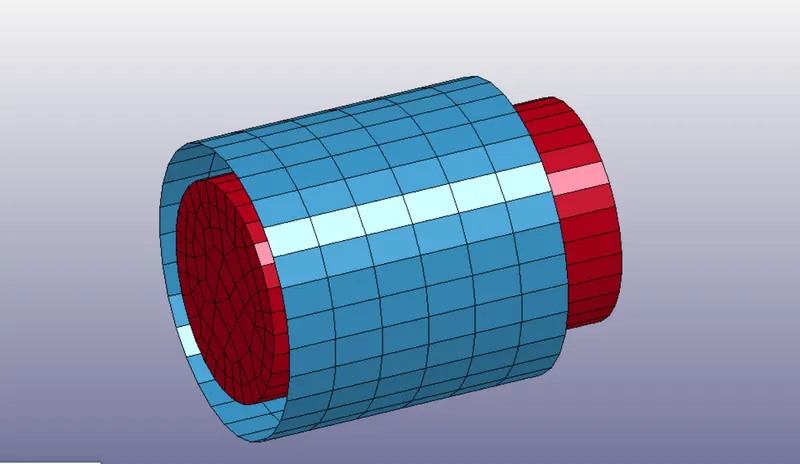
Last frame

In this case we have provided translational and rotational motion to the outer sleeve
As we can see the outer sleeve has moved forward in translation motion along with rotating along its own axis as we have given the boundary conditions. This is how the cylindrical joint behaves, it permits translational and rotation about 1 axis
Translational Joint :
First frame
Last frame
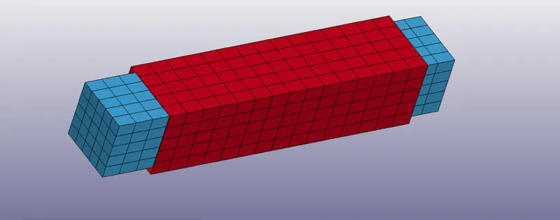
In this case we have provided translational and rotational motion to the outer sleeve
As we have provided rotational motion along the axis we observe that along with the sleeve translating forward the inner beam rotates along with the outer sleeve indicating that there is no relative rotational motion allowed between the sleeve and the inner beam. This is the difference between translational and cylindrical joint (i.e . rotational motion is not allowed)
Revolute joint :
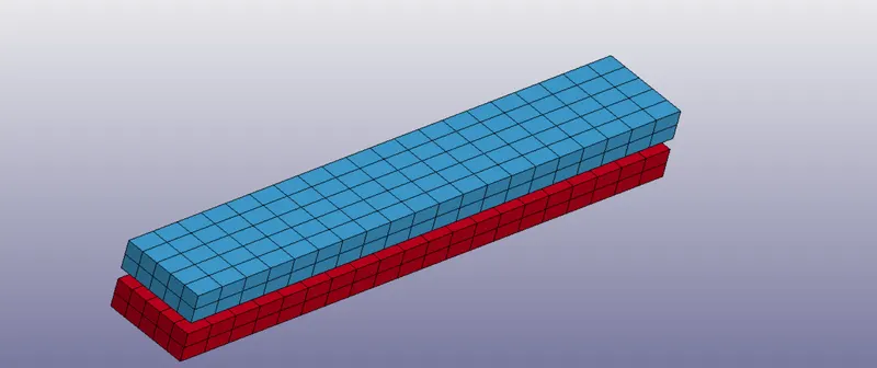
First frame
Last frame
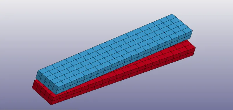
As we can see above the two beams undergo rotational motion about the centre defined axis relative to each other in the form of torsion as shown above.
The revolute joint allows only rotational degree of motion in any 1 axis.
Conclusion :
- Hence we have studied the mechanism of the 4 joints and their behaviour in both rigid and deformable bodies.
- While using the same conditions for a rigid body we need to implement the use of control timestep card as well to maintain the accuracy of the simulation due to reduction in number of calculation per simulation.
Result :
The 4 joints have been created for rigid as well as deformable bodies (total 8 files)