Week 2 Bevel Gear Challenge
Objective : To perform the simulation for the given set of bevel gears using the different mesh sizes provided and establishing the effectiveness of a grid dependency test.
Procedure :
Grid Dependency Test :
A grid dependency test is a method of getting the most accurate results from a particular simulation by utilizing the correct values for all the parameters. For example, let us consider mesh size. In a particular simulation, to find out which mesh size will give us the most accurate results, we can use a grid dependency test.
We start with a coarse mesh of a particular simulation and run it obtaining the results of key parameters like Von-misses stress, equivalent strain, deformation etc. Then we will reduce the mesh size and run it again and we notice that the values change. In this way we keep running it with reducing mesh sizes until we start to obtain mostly similar values(i.e. solution converges)
Then we pick a mesh size which offers the best balance between computational time and accuracy by looking at the data. In this way we finalize the mesh size and hence can use it for future simulations to save time and get accurate results. In this way the grid dependency test can be performed for even other parameters like materials, loads etc.
Setting up the simulation :
Now we will attempt to perform a grid dependency test using the 3 different mesh sizes given to us in the question of 4, 5 & 6mm.
To set up the simulation, first we need to import the required material card of structural steel. This material can be found in the Granta materials library
Structural Steel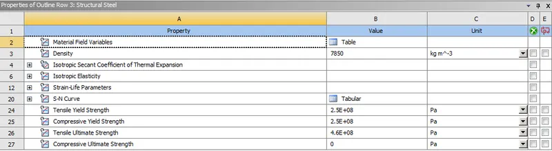
Importing geometry :
Next we import the geometry which the Creo CAD file of the 2 gears which has been provided. The parts are renamed as BEVEL BIG & BEVEL SMALL respectively for ease of understanding.
Material defintion : 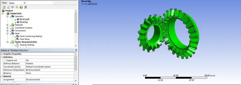
The material structural steel is assigned to the gears for the first case.
Then we will open Ansys mechanical to set up the rest of the simulation.
To set up the contact we go to connections-->contacts and open the contact card.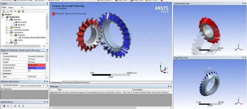
We will create the contact by selecting the faces on both the gears as shown below.The whole tooth face is selected which is one continuous surface on both the gears. So we get 48 and 32 faces from the big and small bevel respectively.
Type = frictional
Formulation = Augmented Lagrange
Interface treatment = Adjust to touch
Next we define the joints for both gears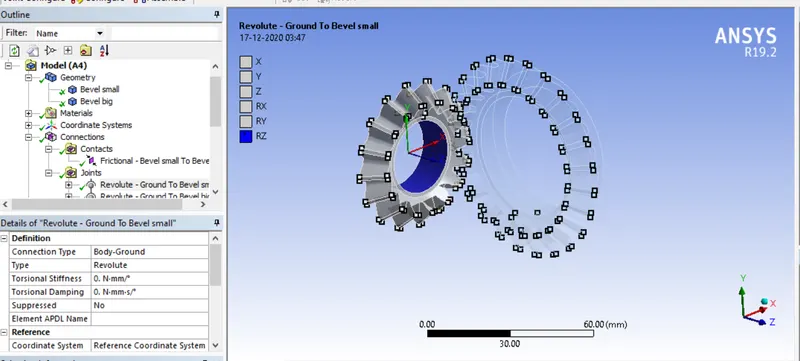
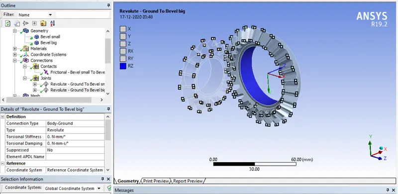
For the scope we select the inner face of the gears to define its axis of rotation. For the bigger gear we reverse the direction of the z-axis to later aide in providing clockwise rotation to it. In this way both the joints are selected as body-ground & Revolute type.
Next a general mesh is generated of 5mm with face sizing applied of 6mm on the toothed surface of both the gears.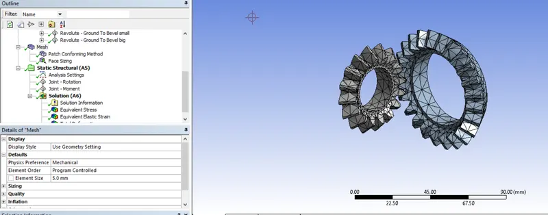
The face sizing is applied since that is the surface in contact and which will experience loads hence we want to study the effect of mesh size on it.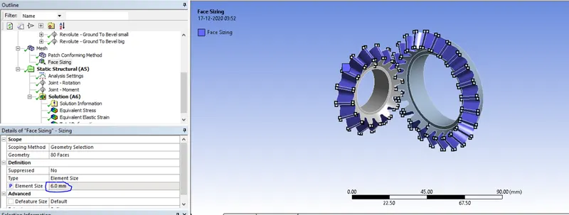
This mesh size is parameterized so that we can later compute the effect of changing this mesh size on the result.
Creation of Joint-loads : Next we assign the motion to the individual gears. This can be done by giving rotation or a moment.
For the first gear we provide rotation by increments of 20 degrees as shown below by inputting data into the table. The motion is given in the form of 6 increments.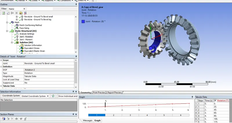
For the second gear, we input a moment in the opposite direction of rotation to the first gear as shown below. The torque provided is of the order of 10000 N-mm which is equal to 10 N-m which is constant from the beginning till the end.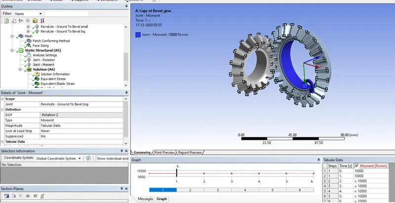
Setting up the analysis settings : Next the analysis settings are selected as shown below, inputting the vvalues of number of steps, initial time-step, maximum/minimum timestep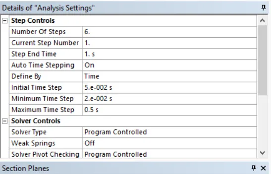
Output Parameters : The following parameters are selected for output from the simulation.
We select the parameter option on the maximum and minimum values on each of these 3 results as shown below as output parameters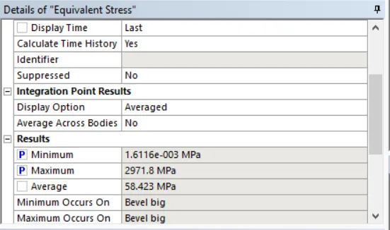
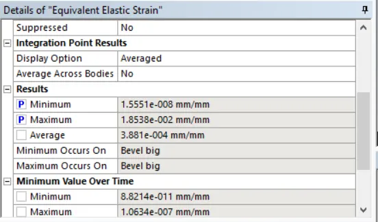
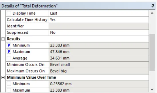
Now looking at the Workbench project page we can see the defined input and output parameters as shown below.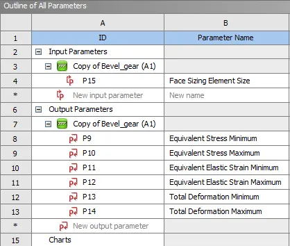
Running the simulation :
Now we can run the simulation for mesh size 6mm (face mesh size).
The simulations were also run individually at mesh sizes of 5mm and 4mm respectively. Since the animations are the same they have been shared just once(for 6mm).
Stress : 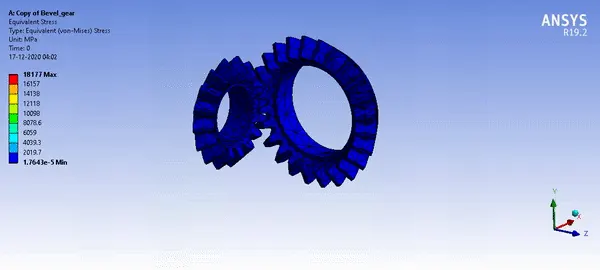
We can see a the simulation running successfully with a peak stress calue of around 2971.8 Mpa and the minimum of 0.0016116 Mpa at the end of the run.
Strain : 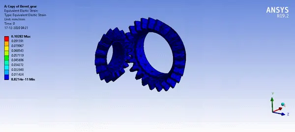
Above we can see the total elastic strain being experienced by the pair of bevel gears, which is found to be a maximum of 0.01853 = 1.8% at the end of the run.
Since we have checked that the simulation runs fine for both 5mm and 4mm without having to change anything else in the simulation we can use parameterization feature of the software. Now for computing the results of these parameters with different mesh sizes we go to Workbench project page and add new parameter in mesh size and create two new rows for 5mm and 4mm respectively.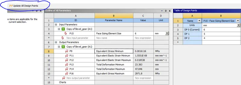
Now we can click on update all design points and the software will calculate the values of these 6 parameters with the 2 new mesh sizes. The result will look like this
This saves us the time of running the simulaton manually by changing the mesh size and executing. Also we can select all our areas of interest to look for convergence as has been selected in the case above.
Table given in simplified format below.
| Name | P15 - Face Sizing Element Size | P9 - Equivalent Stress Minimum | P16 - Equivalent Stress Maximum | P11 - Equivalent Elastic Strain Minimum | P12 - Equivalent Elastic Strain Maximum | P13 - Total Deformation Minimum | P14 - Total Deformation Maximum |
| Units | mm | MPa | MPa | mm mm^-1 | mm mm^-1 | mm | mm |
| DP 0 (Current) | 6 | 0.001611572 | 2971.839652 | 1.56E-08 | 0.018537928 | 23.38268475 | 47.84637021 |
| DP 1 | 5 | 1.46E-05 | 64.68321113 | 7.94E-11 | 0.00036889 | 23.38268495 | 47.9309288 |
| DP 2 | 4 | 6.51E-06 | 38.10185884 | 7.26E-11 | 0.000218588 | 23.38268488 | 47.9053303 |
As we can see for the mesh values of 5 & 4mm the values begin to converge slightly and identical results can be obtained if we keep reducing the mesh size.
Conclusion : Hence the simulation has been run for the mesh sizes of 6, 5 & 4mm and the use of grid dependency test has been realized. Also mesh size of below 4mm should give accurate results for the above simulation.
Result :
Attached below is the simulation with result for 6mm mesh along with parameter results for 5 & 4mm as well.
Bevel Gears