Week - 4 - crash box simulation
Objectives : To study the impact behaviour of the crush tube of varying thicknesses onto a rigid wall and to study the various energies being generated.
Preocedure :
Setting up the simulation :
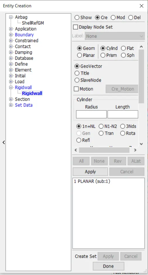
Creating the rigid wall : To create rigid wall go to create entity-->rigid wall-->create, choose the options as planar, select the tail node, click on translate option and give a tranlational of about 20mm.
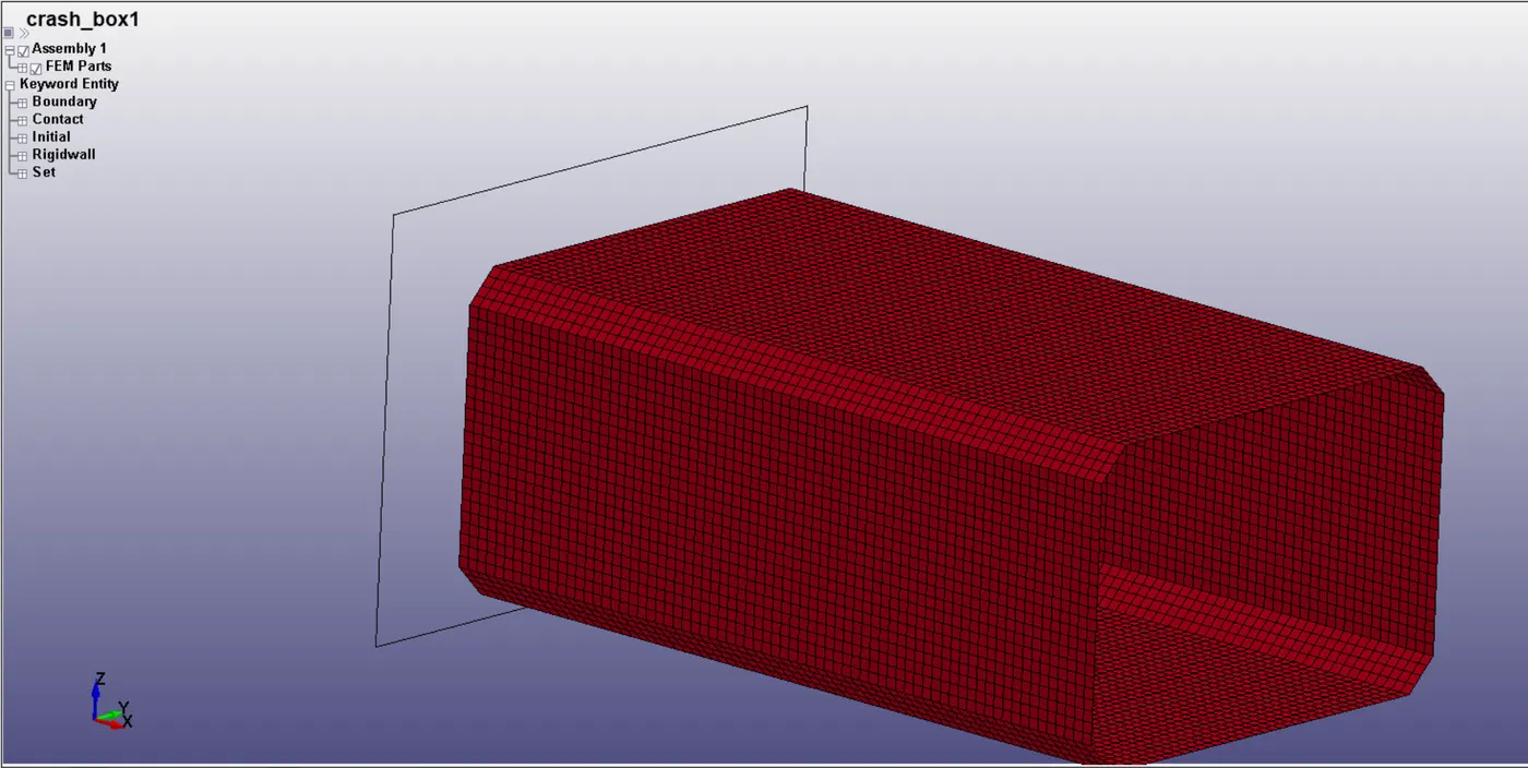
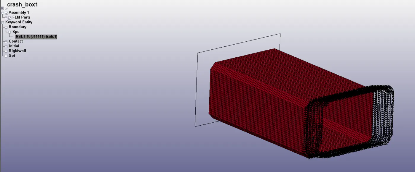
Hence the rigid wall will appear like this ahead of the crash box.
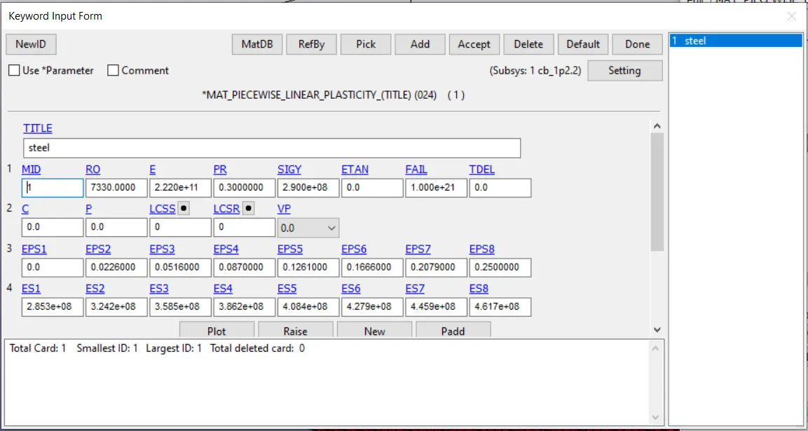
Creating material property : To create material property go to MAT-->select card 24 and fill in the options suitably. For this material card, material information about stress and strain rates was also inputted from online sources as follows. Inputted unit system is kg, s, m.
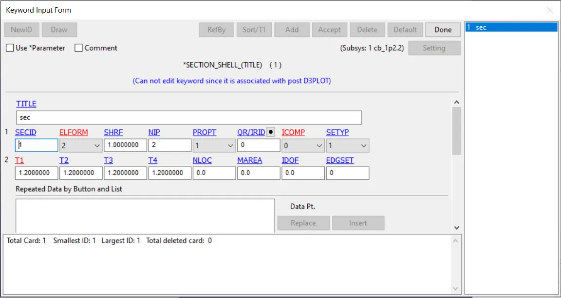
Creation of Section : Next we create a section by going to Section and selecting the following options in the card for shell elements. Assign a thickness of 1.2mm to the crash box.
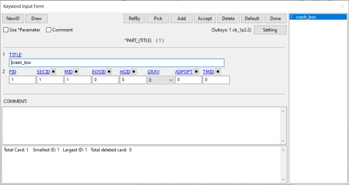
Assigning to part : Next, we assign the material and section to the crash_box part by entering the material and section Ids in MID and SECID respectively.
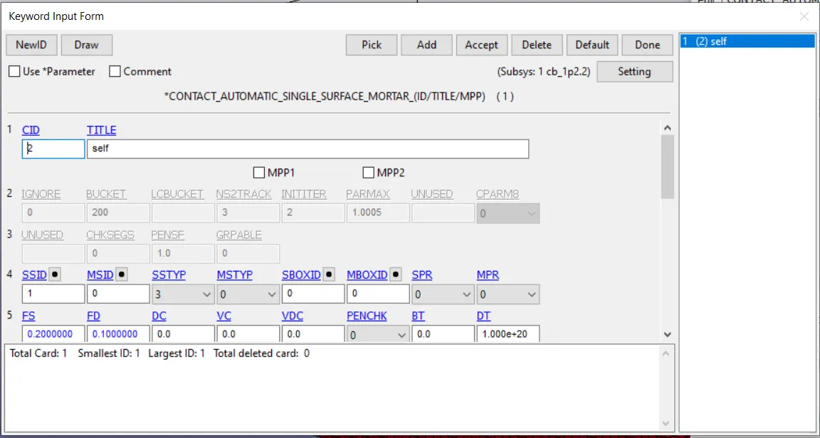
Defining Contact : Next we define the contact for the crash box to collide with itself. We go to contact and choose
CONTACT_AUTOMATIC_SINGLE_SURFACE_MORTAR, and enter in the following values and define the slave as partid of the box. We can aslo use SINGLE_SURFACE_AUTOMATIC for this purpose. Give the name as "self".
Boundary Creation : Next we provide certain boundary conditions for the simulation.
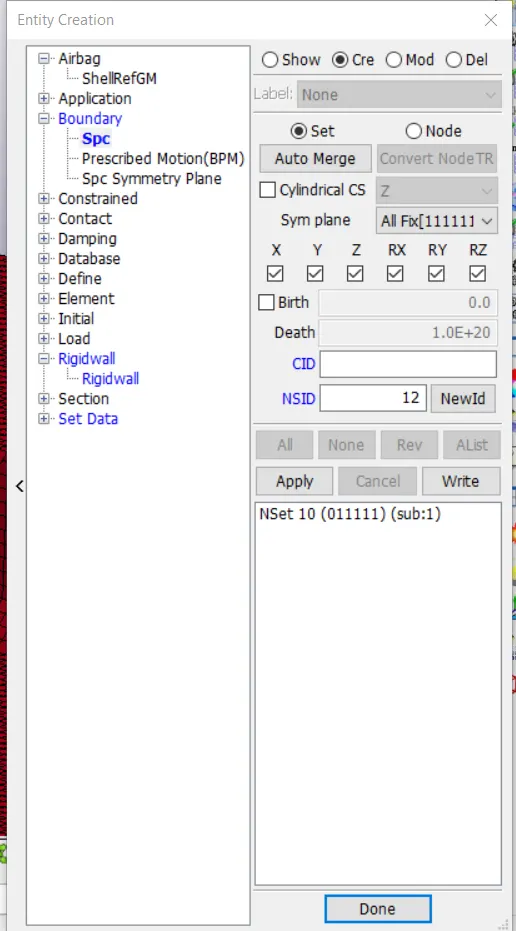
Go to create entity-->spc-->create and then select the nodes on the opposite edge of the crash box and lock them in all directions except translation in x. This is to ensure the crash box goes straight forward ato collide with the rigid wall.
Assigning Initial Velocity :
Go to create entity-->SET_NODE-->create and then select-->by part to create a node set consisting of the complete crash box to which we will assign initial velocity to.
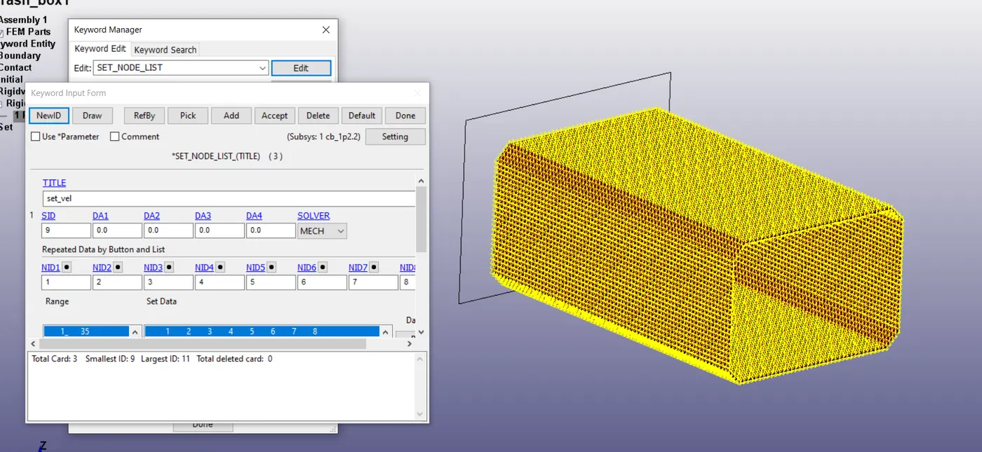
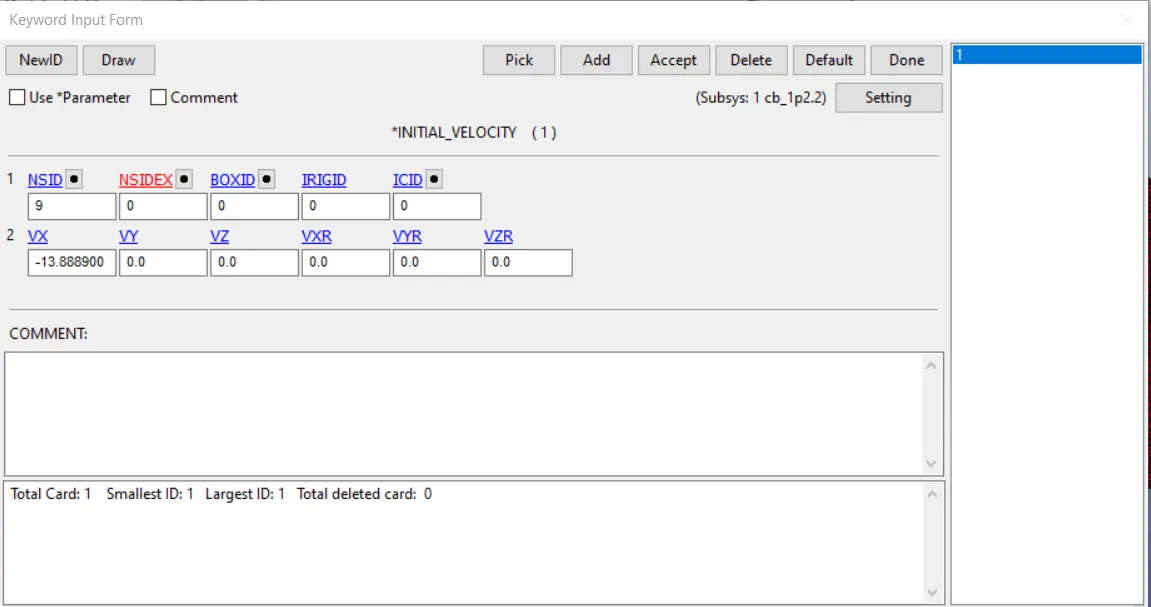
Name it as set_vel. Next go to initial-->velocity and assign velocity of 50kmph(13.889m/s) to the node_set created earlier in the negative x direction.
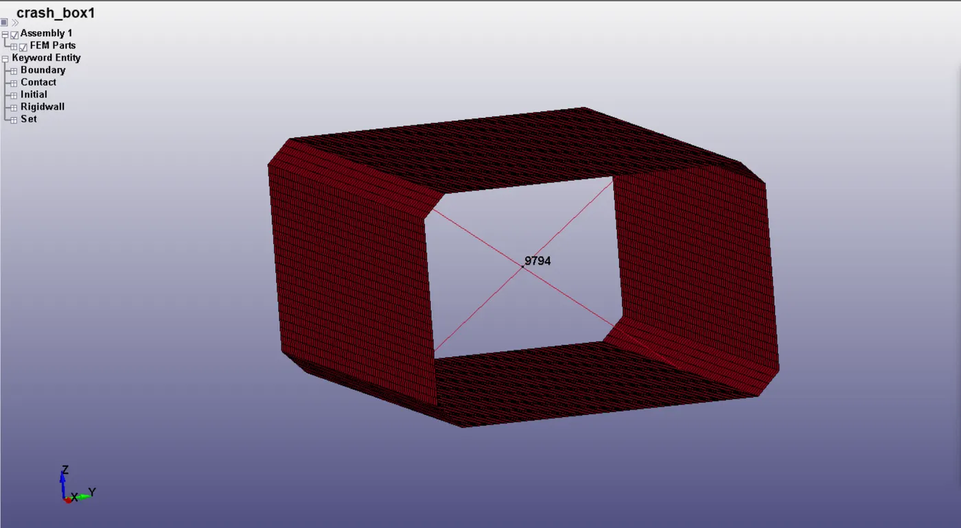
Creation of central node : A node is created in the centre of the crush tube using CNRB to later on measure its acceleration in the post-processing.
Control parameters : Next we select the control parameters, which govern the conditions in which the simulation will be computed.
Control_accuracy:
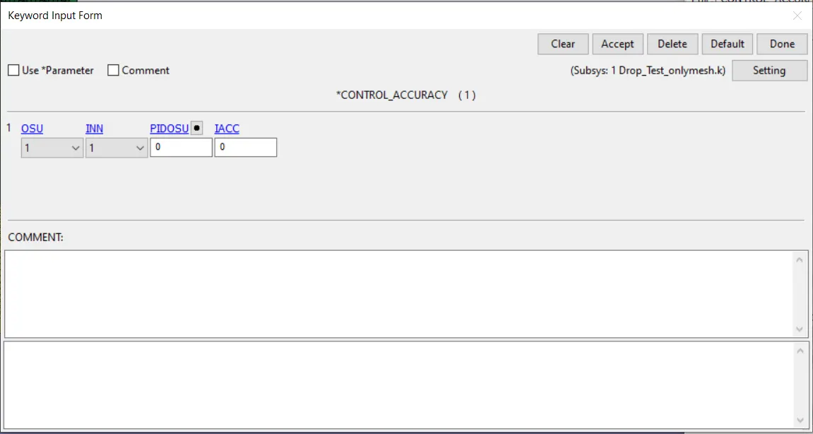
These options are selected for this simulation, objective stress update is on.
Control_energy:
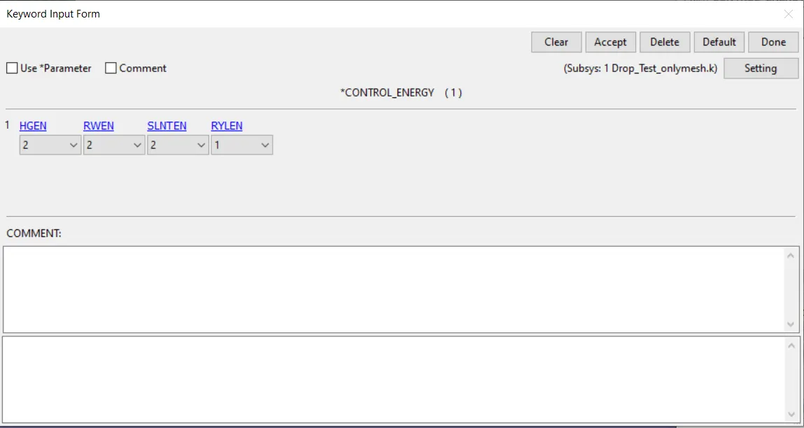
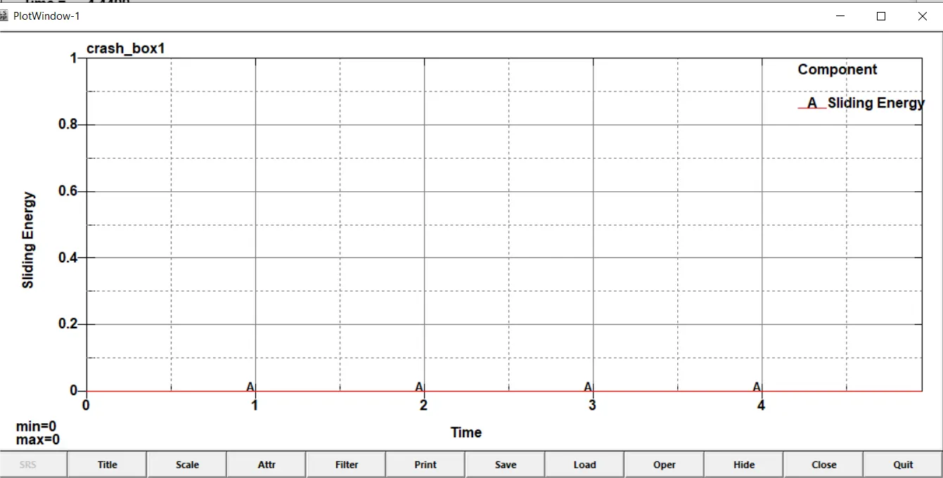
These options are selected so that hourglass energy, sliding interface energy and stonewall energy dissipation are calculated.
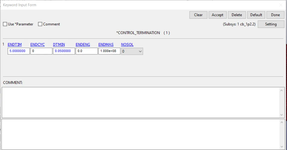
Control_termination : This option decides the termination time which is set at 5 seconds
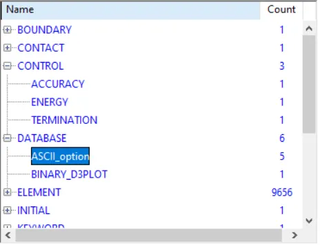
Database options : Next we select the options which we want to see in the output characteristics. The following options are selected in Database_ascii. The options GLSTAT, SLEOUT,RCFORC, NODOUT, ELOUT are shosen to show the energy curves, sliding energies, interface forces, nodal accn/disp/velocity and element forces respectively.
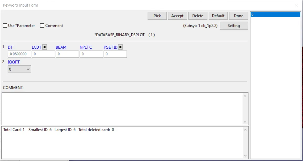
The following options are selected in Database_binary_plot. The timestep is kept at 0.05 seconds as shown below.
Now all the pre-processing is complete and we are ready to run the simulation.
Running the simulation : Now we will run the simulation
Post processing :
Crash behaviour : We can see that the crash box aprroaches the rigid wall at the given speed, compresses very minutely and bounces off the rigid wall without much deformation. The crash happens between 29 and 30th frame out of a total 101 frames.
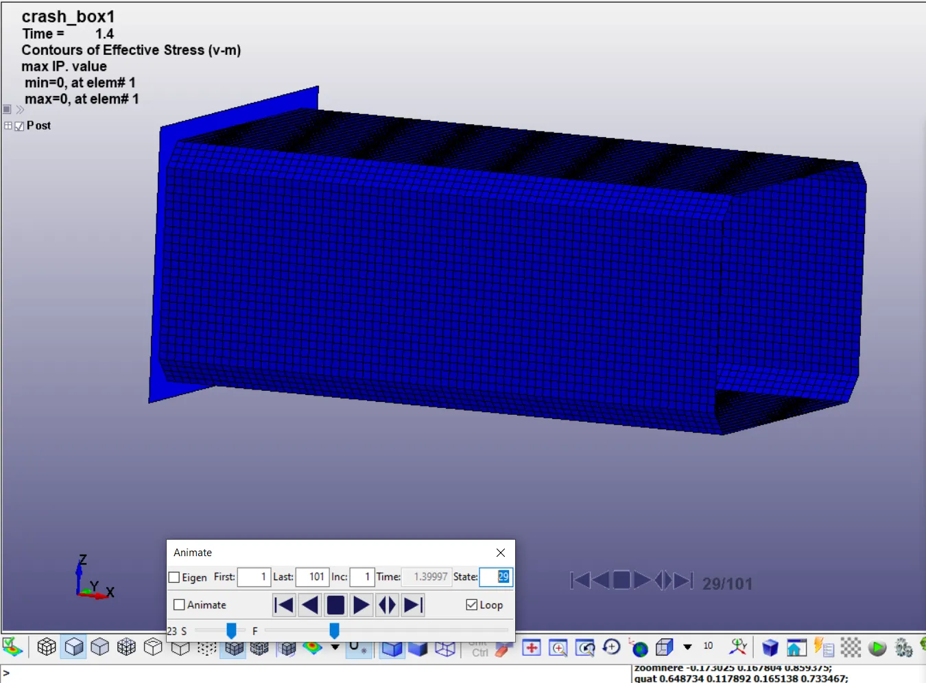
We can see the shockwave propogating through the structure as shown below. Given below is a frame-by-frame progression of the shockwave.
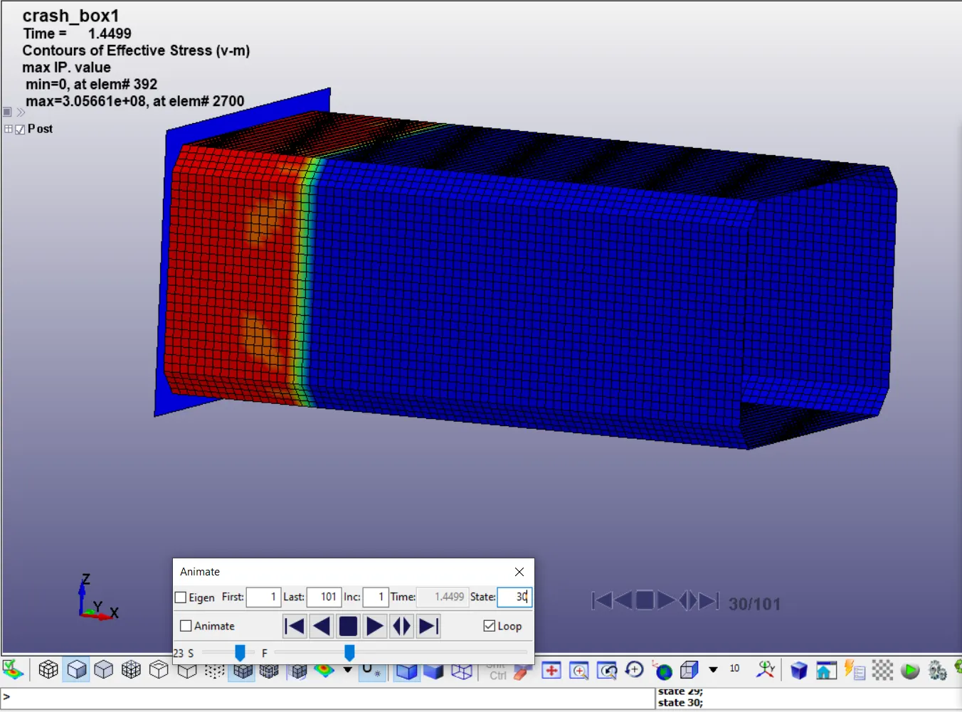
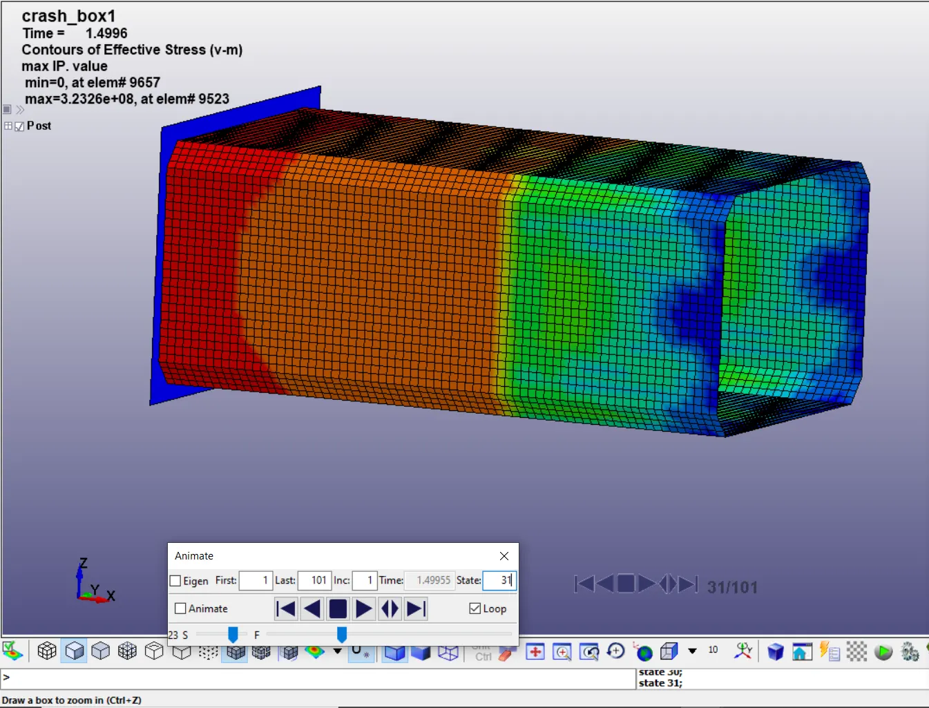
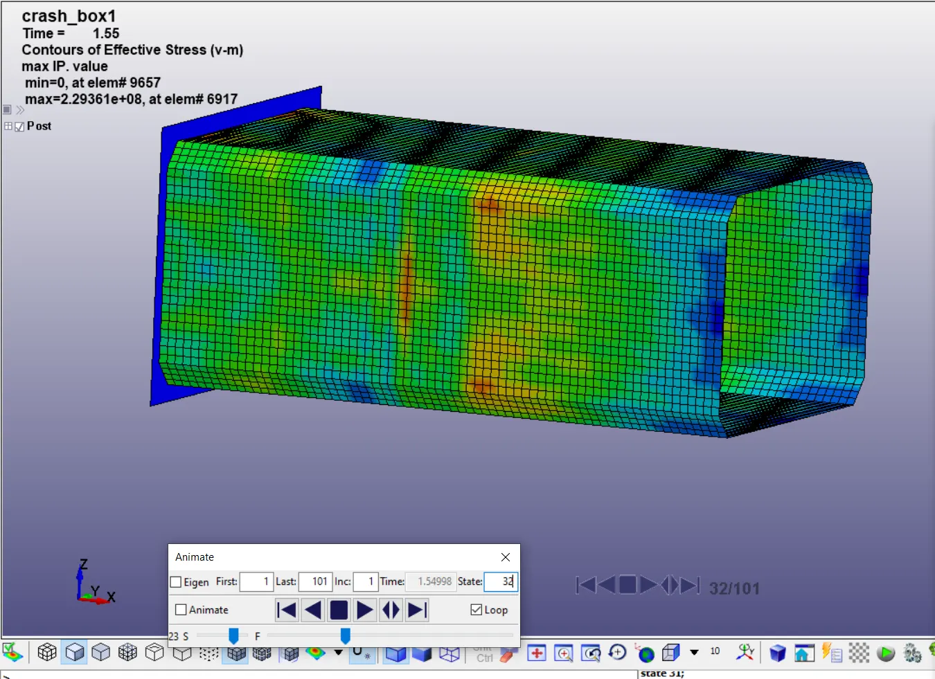
The crash box aprroaches the wall at 13.889 m/s and rebounds off it much slower until the end of the simulation. There is very slight compression upon impact which is apparent by a slight increase in width of the box at impact.
Normal stress along the length of the crash box :
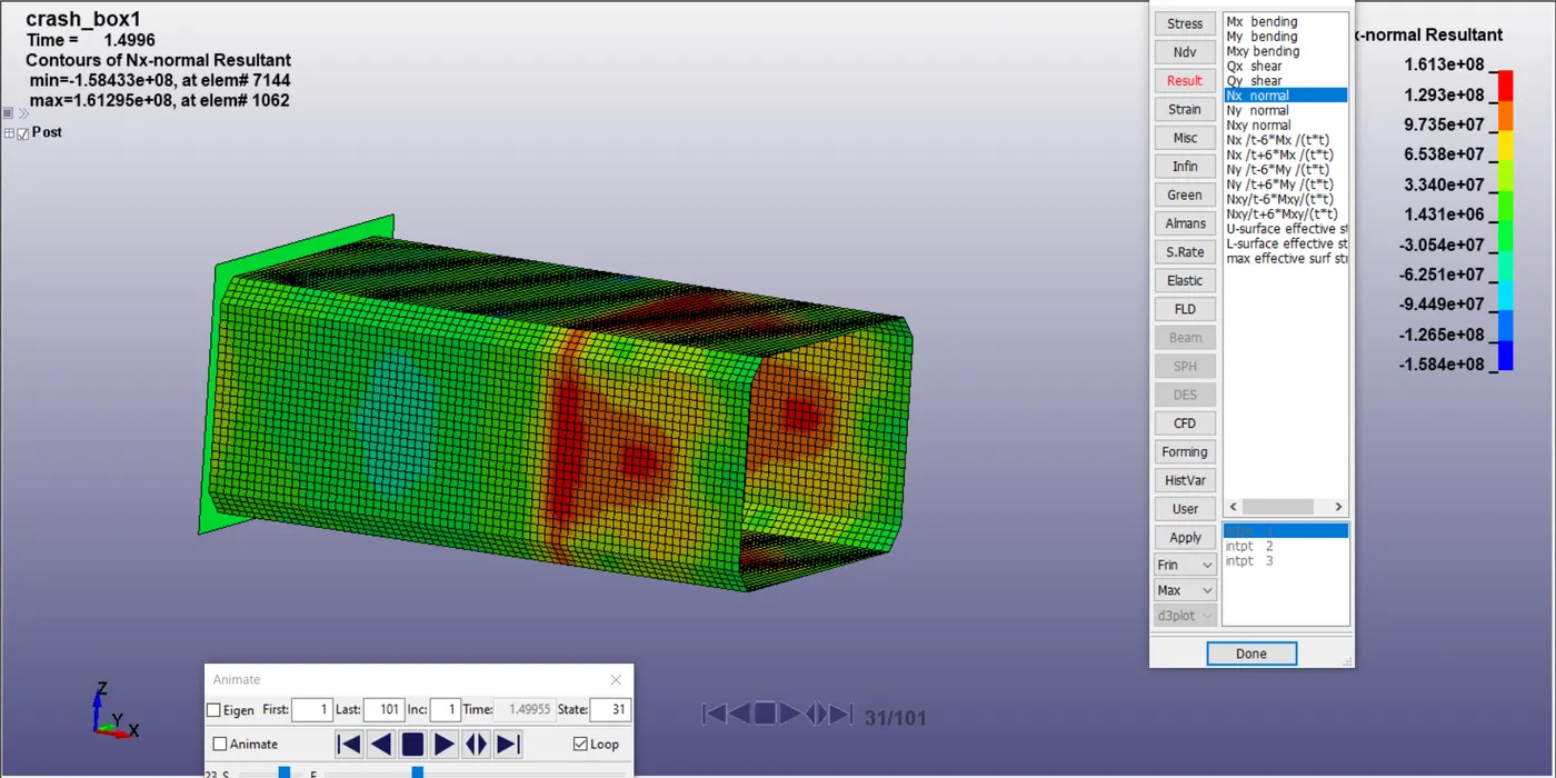
The normal stresses acting in the x-direction at the frame just after collision are 0.1613 Gpa. We can see the pressure wave passing through the box.
Acceleration plot at central node :
The acceleration of this node is plotted below. In translation it becomes 9795.
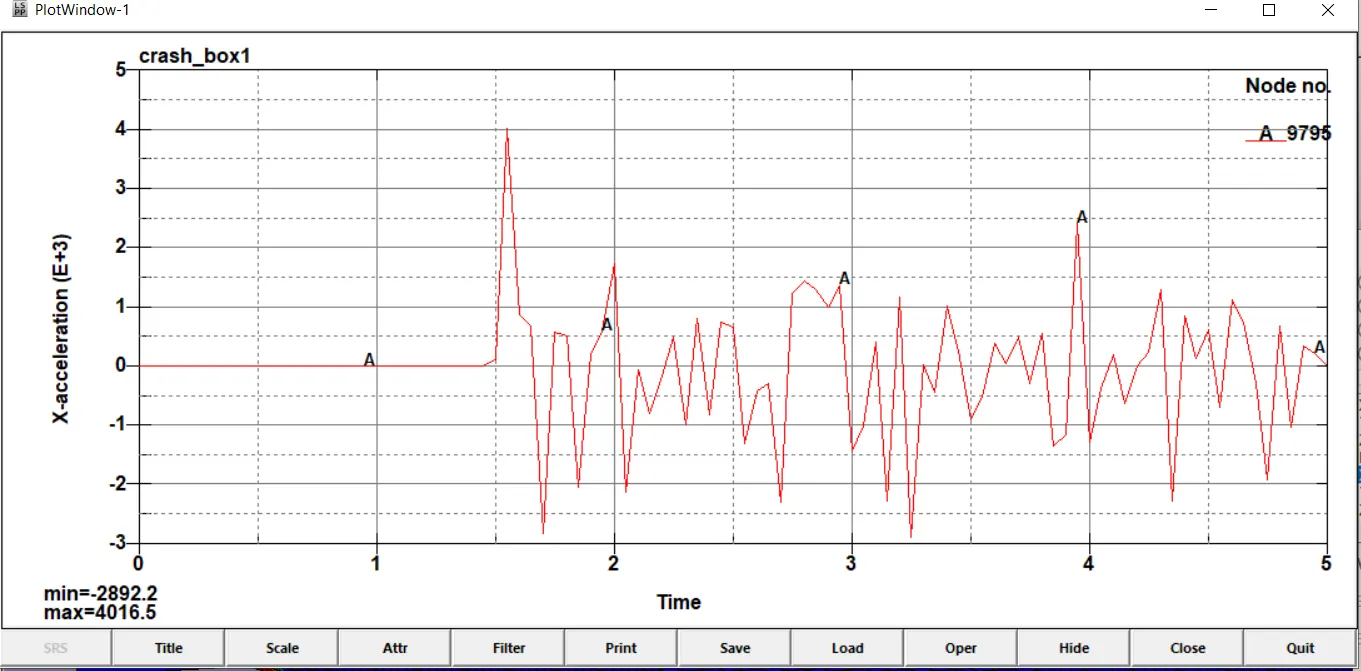
We can see above that up until the point of contact with the wall, the node has no acceleration as it moves at a constant speed along with the box. However aftere the contact at around 1.5 seconds, it undergoes acceleration in a zig zag manner consisiting of positive and negative acceleration indicating the oscillation of the node to and fro from the mean position.
This is clear when we see the acceleration distribution in x-direction after impact for the elements as well.
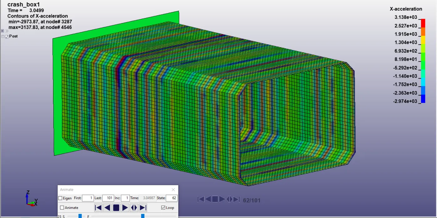
This is indicative of the propogation of shockwaves through the body wich move by oscillating back and forth in a wave like manner.
Maximum Directional Stress and Strain along X & Y axes :
Maximum directional stress along x-axis is around 0.2 Gpa:
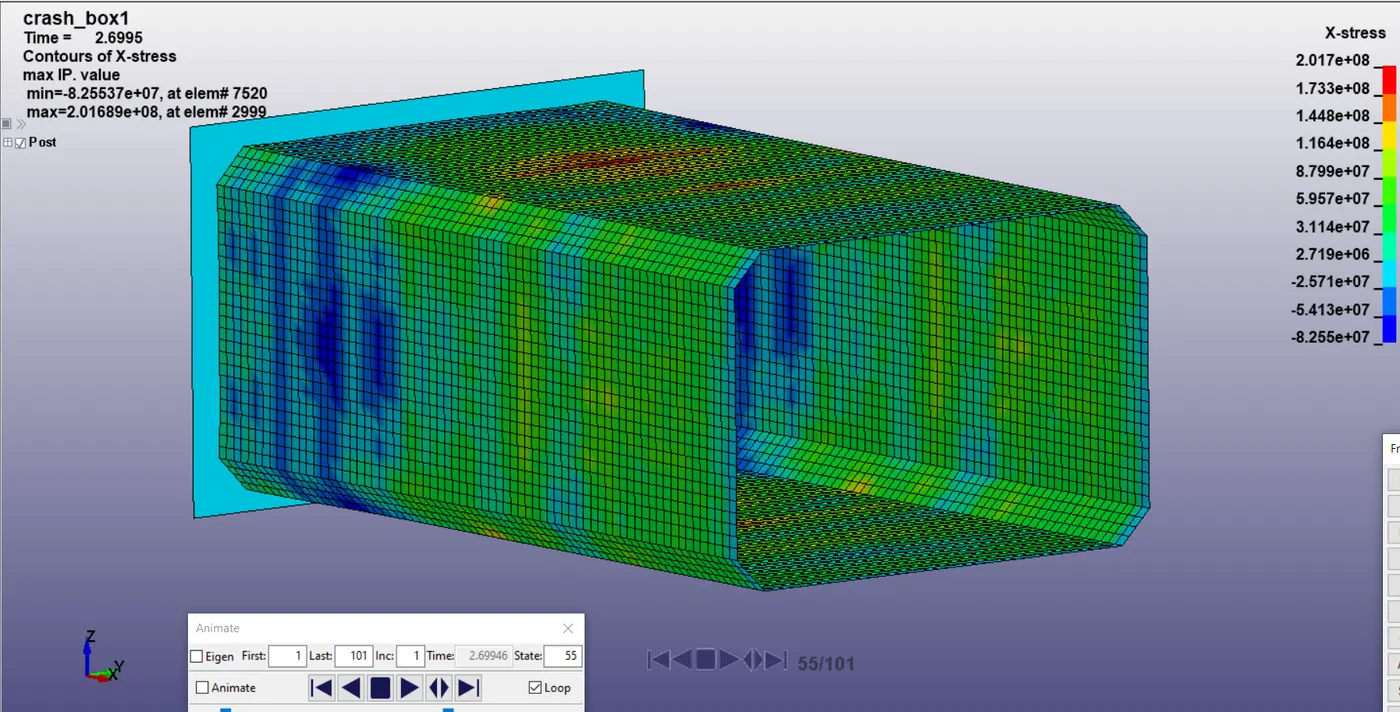
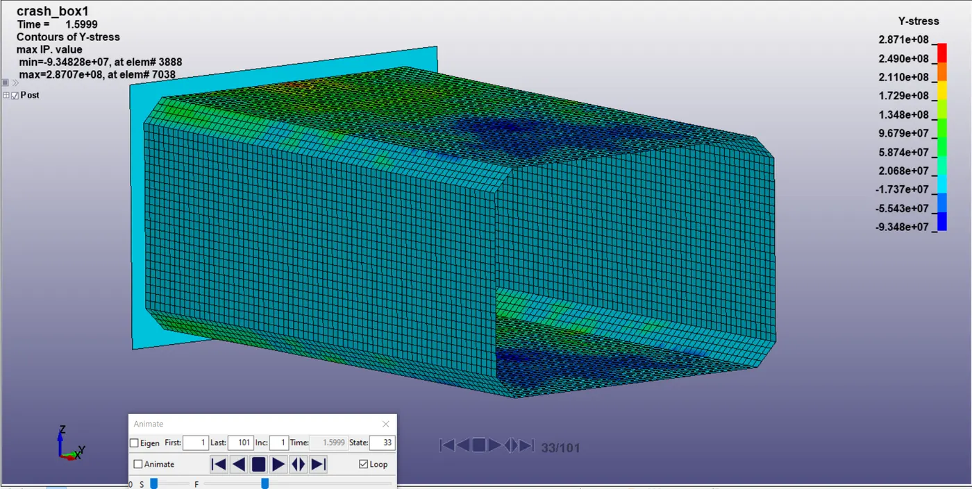
Maximum directional stress along y-axis is around 0.28 Gpa:
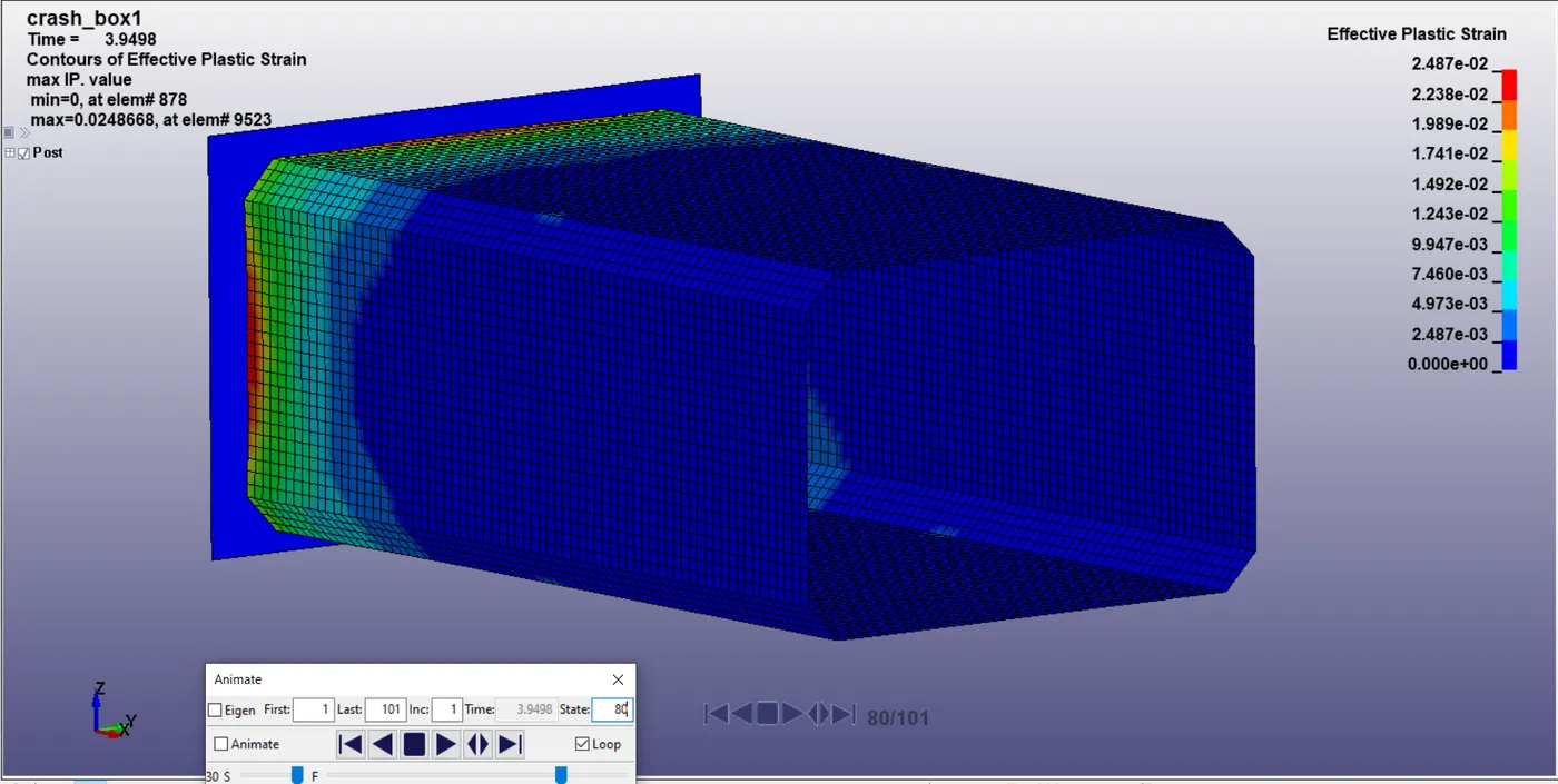
Maximum plastic strain is around 0.028.
Plot of Energies :
Internal Energy v/s Kinetic Energy:
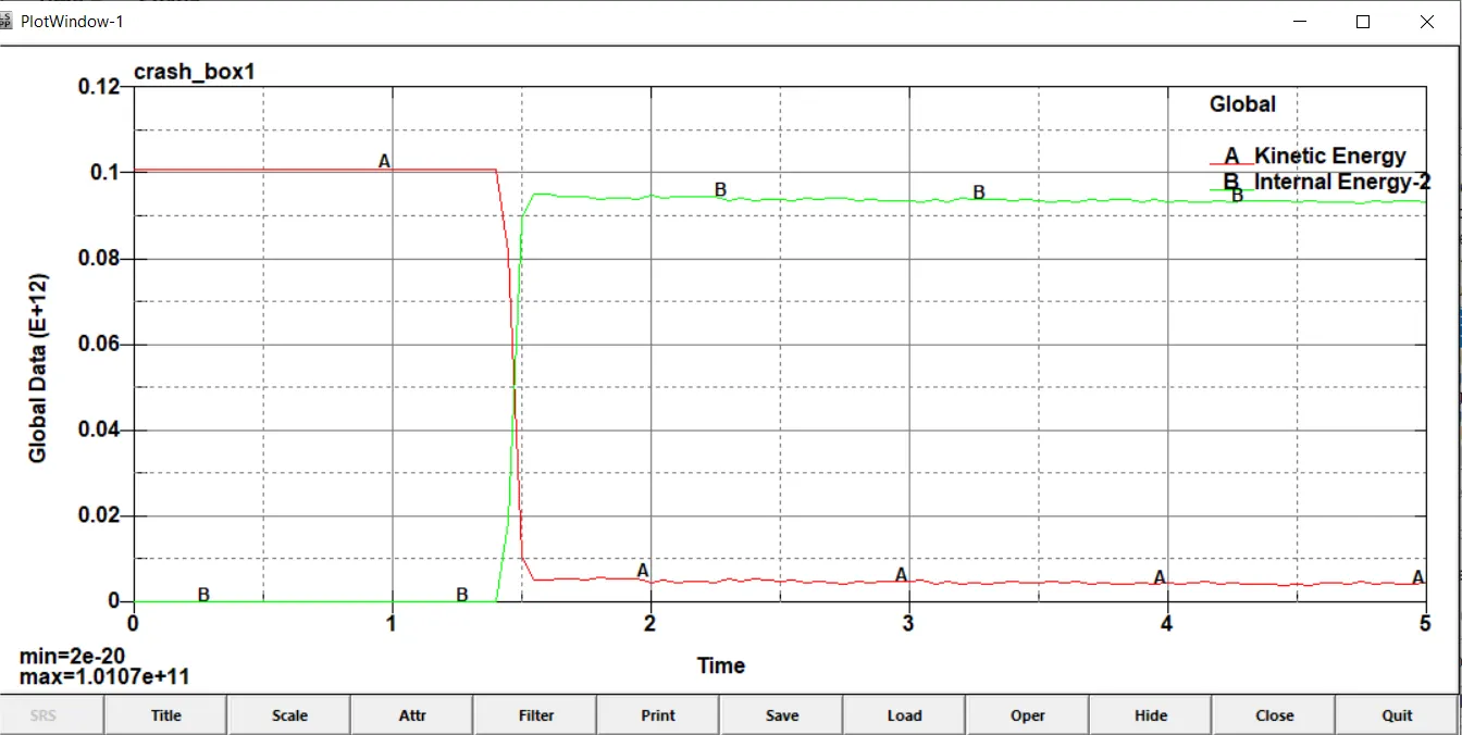
As we can see the amount of Kinetic Energy lost is the amount of internal energy gained more or less with few losses indicating the simulation has good energy balance and is accurate. The energies are of the order of 10^12 Joules.
Total Energy :
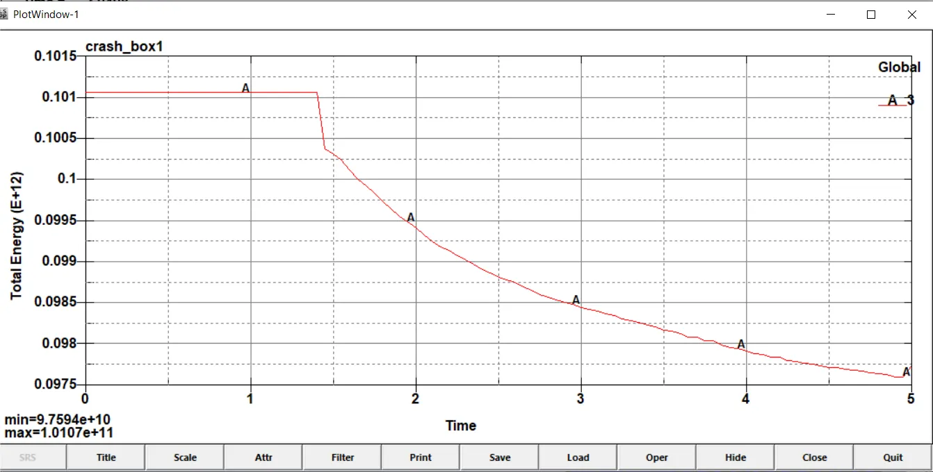
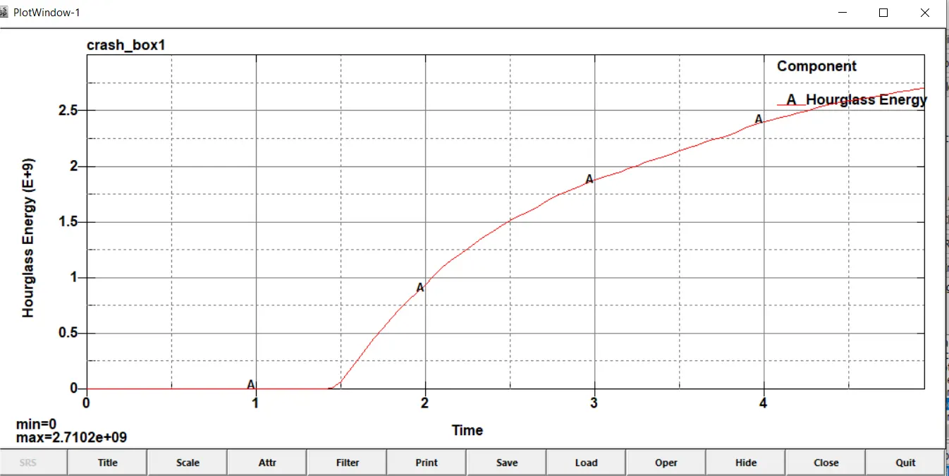
The total energy of the simulation remains more or less conserved as is apparent in the graph shown above with loss of around 3.5% which can be attributed to hourglass energy.
Hourglass Energy :
The plot of hourglass energy is given below.
Sliding Energy :
Timestep :
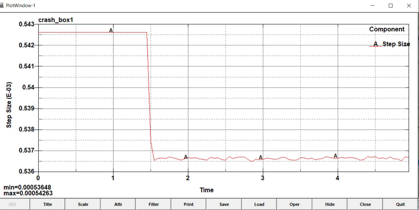
Given below is the plot of timestep variation as the simulation progresses. The variation is not much and hence the simulation is stable.
Comparison with 1.5mm thickness :
Next we change the thickness of the section to 1.5mm to study the change in crash behaviou properties of the section.
Von-misses Stress :
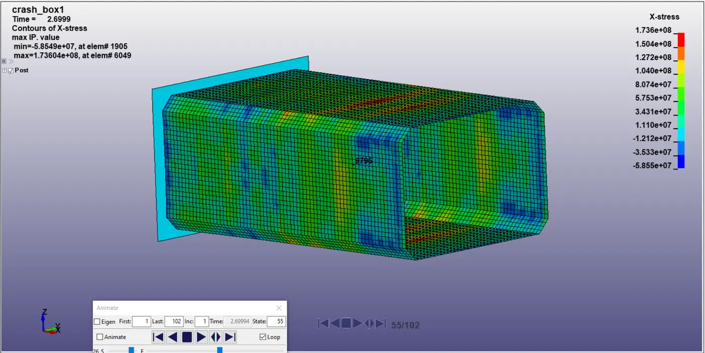
At frame 55 we compare stress in x-direction
1.2mm thickness (max = 2.01689e+8)
1.5mm thickness (max = 1.73604e+8)
At frame 33 we compare stress in y-direction
1.2mm thickness (max = 2.8707e+8)
1.5mm thickness (max = 2.46251e+8)
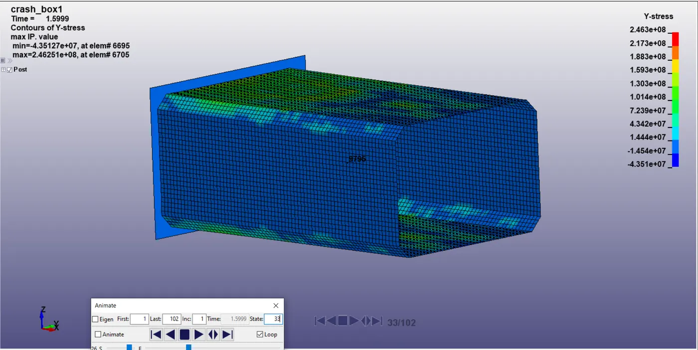
Hence we can see that the stresses are lower in the 1.5mm thickness crash box which is expected due to larger cross sectional area of the box thereby decreasing the pressure acting on the box.
Effective Plastic Strain
(1.2mm) Maximum plastic strain = 0.0248668
(1.5mm) Maximum plastic strain = 0.0250033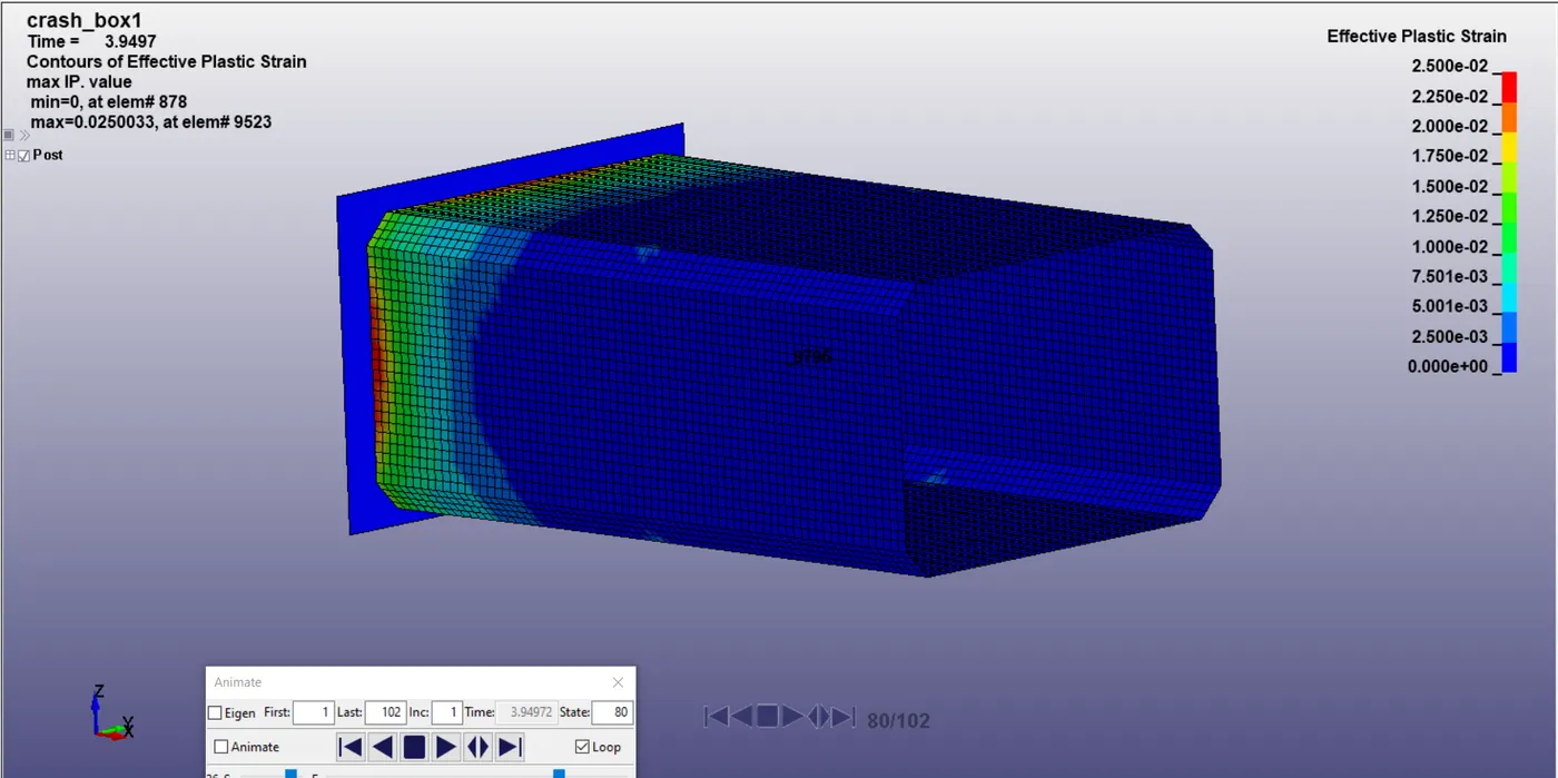
Strain however is higher but by a very small margin in the thicker 1.5mm box due to the availability of more material in the cross section to deform thereby causing slightly more strain but at the benefit of reduced stress.
Conclusion : Hence we have successfully studied the behaviour of crash boxes of different cross section area in a crash simulation and obtained the desired output.
Result :
Google Drive Link : crash_box_1.2mm