Week 4 -Wire Bending Challenge
Objective :
To perform the simulation of the given wire bending and obtaining the desired results of stresses and strains as required.
Procedure :
Setting up the simulation
To set up the simulation, first we need to import all the required material cards such as Structrual Steel for the rollers and Copper Alloy NL, Aluminium Alloy NL, Magnesium Alloy NL for the wire
The above materials can be found in the General non-linear materials library.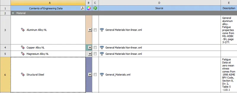
Importing geometry :
Next we import the geometry which has been provided. Rename the components to Wire, Lever and Wheel respectively.
Material defintion :
The material Copper Alloy NL is assigned to the wire segment and Structural Steel is assigned to the rollers.
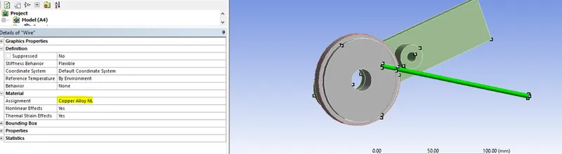
Then we will open Ansys mechanical to set up the rest of the simulation.
To set up the contact we go to connections-->contacts and open the contact card.
We will create 2 contacts,
1)Between Wire and Lever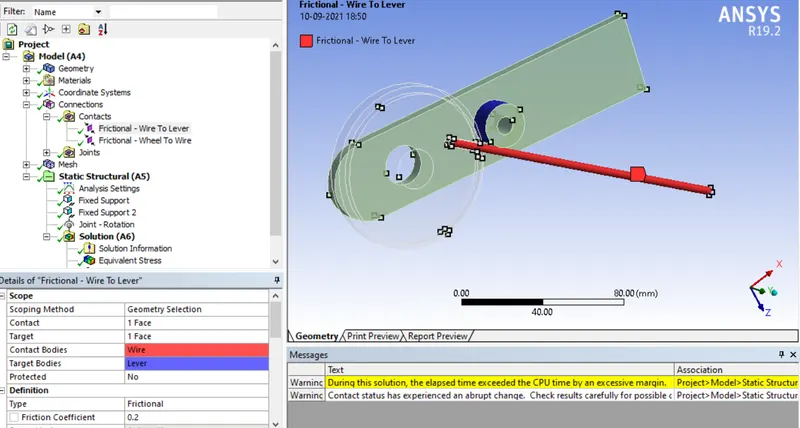
2)Between Wire and Lever
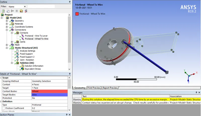
Type = frictional
Coefficient of friction = 0.2
Formulation = Augmented Lagrange
Normal stiffness factor = 0.1
Interface treatment = Add Offset, ramped effects
Next we mesh the components.
A tetrahedron mesh style is applied on the entire geometry. This is followed by a face sizing of 2.2mm on the wire and lever.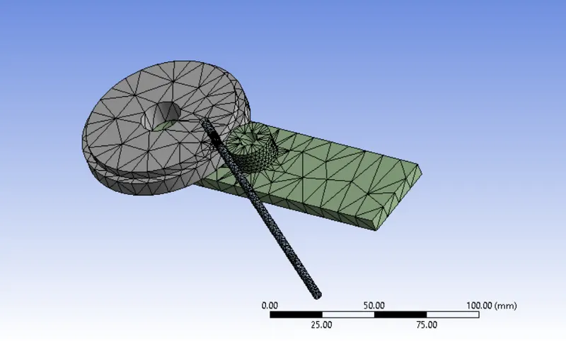
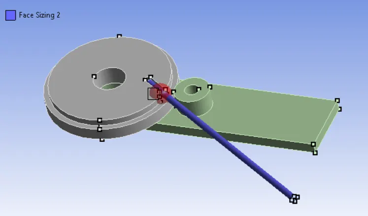
Next a face sizing of 0.8mm is applied along the sphere of influence of radius 7 mm as shown below.
Creation of joints:
A revolute joint is created on the inner circular surface of the lever with body-ground configuration and free to rotate in the z-axis.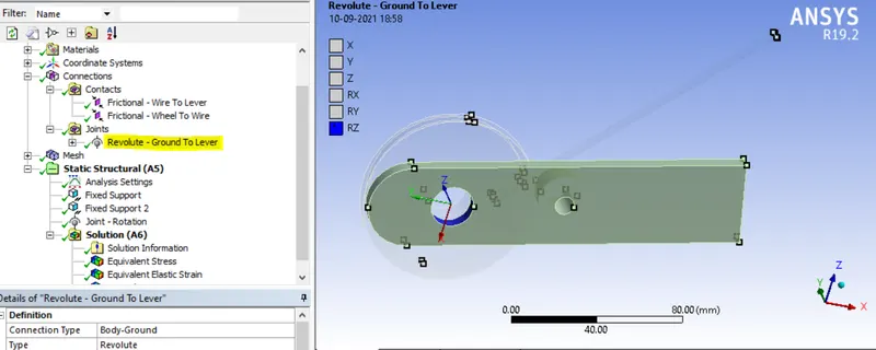
Analysis Settings :
Next we go to analysis settings to set up the kinematics of the simulation
The analysis is run for 8 steps using the following conditions. All the steps are chosen and the following criteria are entered as shown below.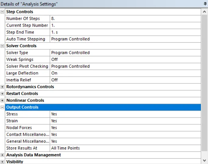
Supoorts : Next we create fixed supports to keep the wire bending apparatus in place while bending the wire.
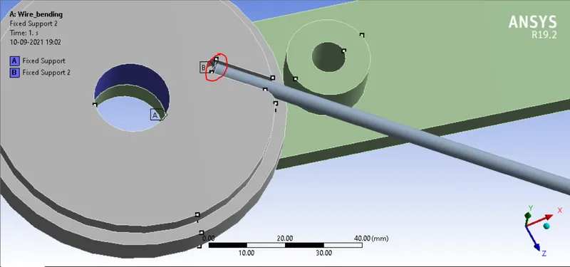
The inner face of the wheel and the end face of the wire (circled in figure) are given fixed supports so that they do not move during the simulation.
Joint-Loads :
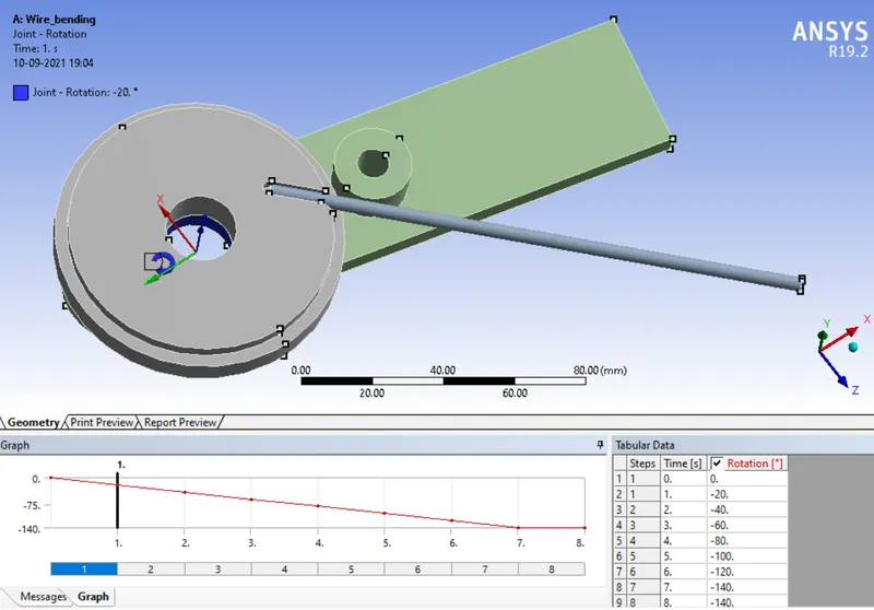
Next the revolute joint is given a joint load in 8 steps as shown above in increments of 20 degrees along rotation in the z-axis.
This provides rotary motion to the lever which will cause the wire to bend along the outer race of the wheel.
Output Parameters : The following parameters are selected for output from the simulation.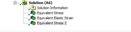
The equivalent stress and strain are selected for the wire segment.
Running the simulation :
Next we run the simulation. The simulation takes about 15 minutes to run as we can see from the runtime below.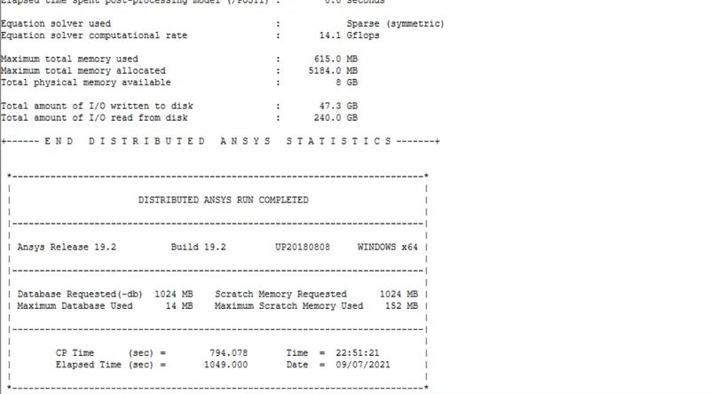
The simulation is run in the same way changing the material assignment of the wire to Aluminium Alloy NL and then Magnesium Alloy NL as well.
Post-processing :
Equivalent stress :
Copper Alloy NL :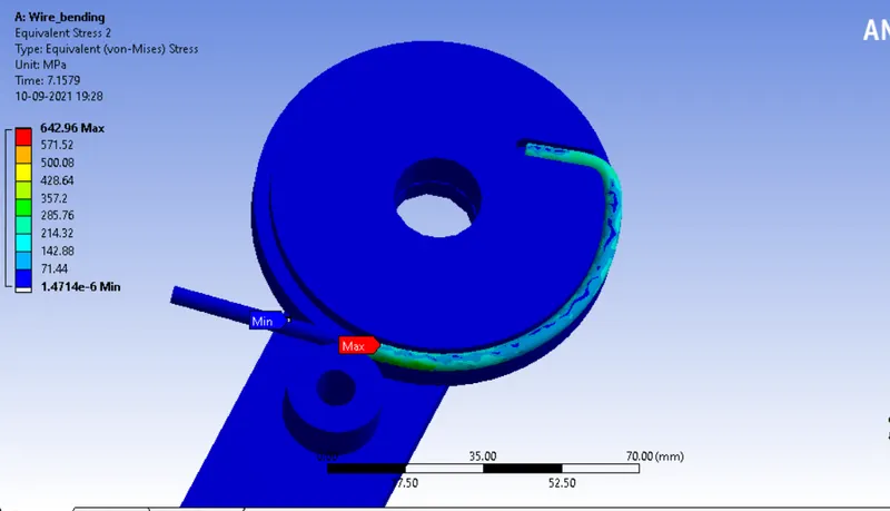
A peak stress of 642.96 Mpa is obtained in the wire segment.
Aluminium Alloy NL :
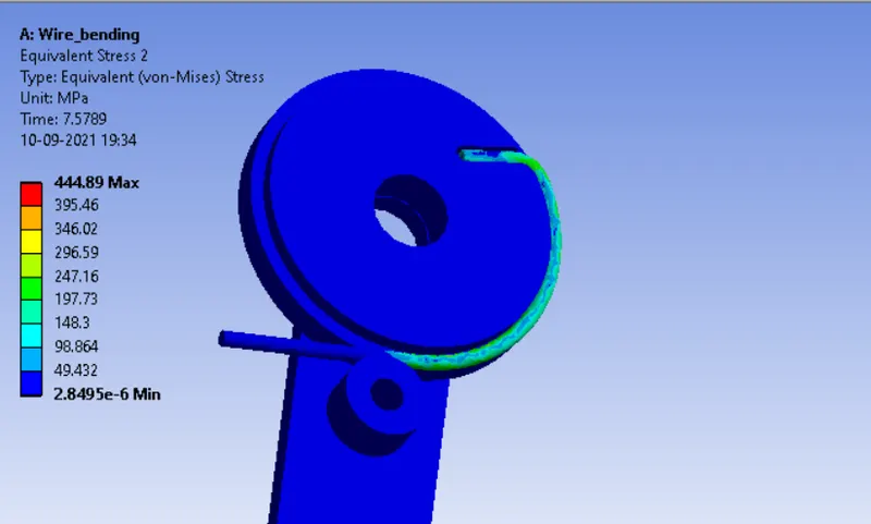
A peak stress of 444.89 Mpa is obtained in the wire segment.
Magnesium Alloy NL :
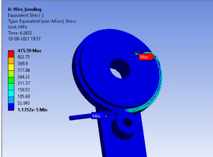
A peak stress of 475.59 Mpa is obtained in the wire segment.
Equivalent plastic strain :
Copper Alloy NL :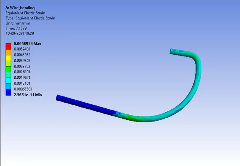
A maximum plastic strain of around 0.00589 in obtained in the wire segment.
Aluminium Alloy NL :
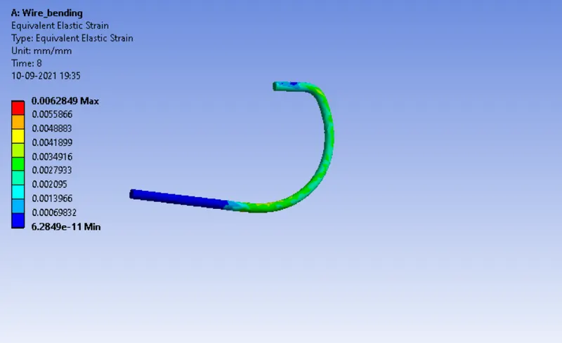
A maximum elastic strain of around 0.00628 in obtained in the wire segment.
Magnesium Alloy NL :
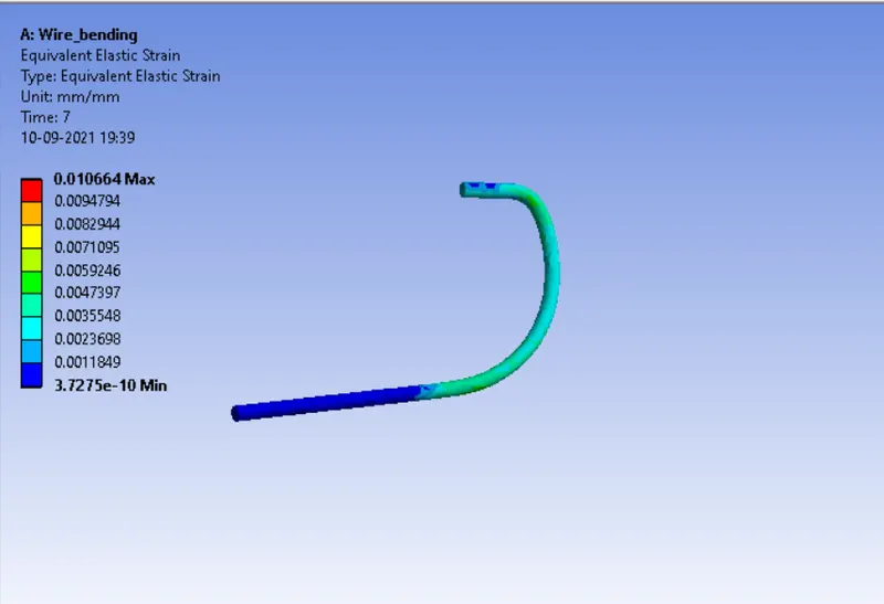
A maximum elastic strain of around 0.010664 in obtained in the wire segment.
Conclusion :
The Copper wire experiences most amount of stress, whereeas the Magnesium wire experiences most strain.
Hence the copper wire rolling analysis simulation has been performed successfully and the desired output has been obtained.
Result : Attached file can be accessed at the link below.
Wire_bending_Simulation