Week 9 - Attachment Feature Creation - Challenge 1
RIB DESIGN
Ribs provide a means to economical stiffness and strength in molded parts without increasing overall wall thickness
They also facilitate
1) Locating & arresting components of an assembly.
2) Providing alignment in mating parts.
3) Acting as stops or guides for mechanisms.
Proper rib design involves five main issues :
1) Thickness
2) Height
3) Location
4) Quantity
5) Manufacturability
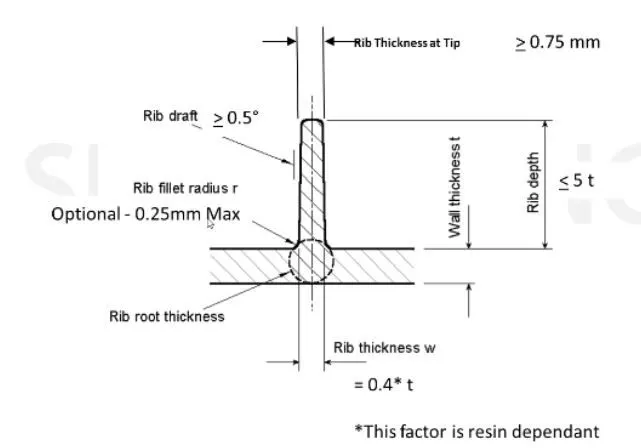
Draft :-
-0.5 degrees per side minimum.
-Allows the ribs to release from the mould
Rib Thickness (w) :- [ w=0.4*t ]
-Measure base thickness of the rib at tangent of radius if radii are modeled in
-The larger the area at the base of the rib, the more retained heat.
-The retained heat causes more shrinkage, which causes sink.
-Minimum thickness, which will be at the top or tip of rib = .75mm
Rib Fillet (r) :-
-Optional Rib Fillet radius = 0.25mm max
-Do not want to significantly increase rib thickness
-Must not violate 40% thickness requirement
Rib Depth / Height :-
-Rib height < 5* nominal wall thickness.
-Limited by draft & thickness requirement.
Procedure to make the Rib :-
1) Create a Plane and a point where we want the base of the rib.
2) Create a Sketch and Draw a line with the length of the rib.
3) Extude the line with surface workbench and make a surface.
4) now with Part work bench thicken the surface with the thickness of surface.
5) Now give Draft and edge fillet to the rib.
6) Added the rib to the main body.
7) Make one more rib as above with appropriate thickness.
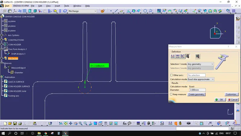
Rib Root Thickness :-
Rib Root thickness must me a value which is nearer to the thickness of the wall thickness, Our wall thickness is 2.5 mm and rib root is having a thickness of 2.686mm which satisfy our condition.
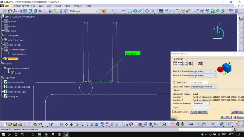
Distance between Ribs :-
Desired distance is 2 times the wall thickness in our case wall thickness is 2.5mm so 5 mm is desired distance and we have 5.004 which is correct.
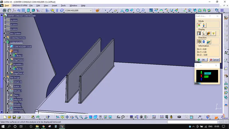
Steps to do draft analysis:
1) Use Generative shape Design, Open Feature draft analysis option from Insert > Analysis > Feature draft analysis.
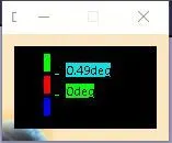
2) A new window pops up by default it will be in quick analysis mode. Change the range to .49deg.
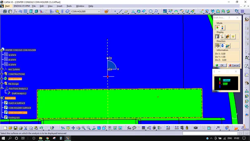
3) Next you have to position the compass on the tooling axis by dragging the compass from the top right corner of the working area. The W axis of the compass should be inline with the axis.

4) Then you have to define the compass by click on the compass icon on the draft analysis window. Then lock the position of the compass by clicking the lock icon.
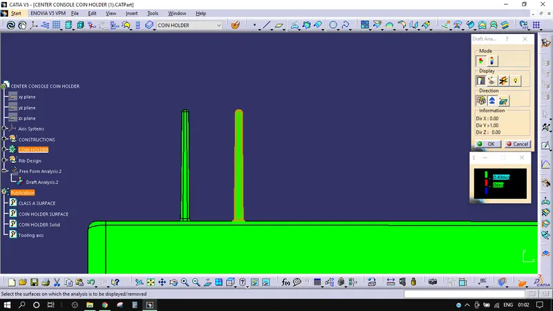
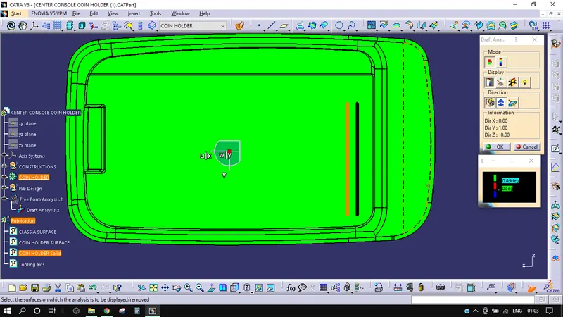
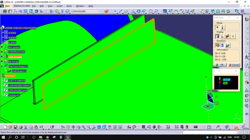
5) After that select the surface and the whole surface will show a color range. Here the rib is fully in green color, which means all faces are having a minimum draft angle and it’s good for manufacturing. If any face is showing blue or red color we have to work on that face to give a good draft.