Side crash simulation on Dodge Neon with a rigid pole
Side crash simulation on Dodge Neon with a rigid pole
Introduction :-
Side crashes are the second most common type of accident. They cause the highest number of critical injuries relative to the accident rate. One reason for this is the spatial proximity of the occupant to the deformation zone. There are different test standards for the side impact. These are the side crash according to ECE-R95 (European standard) and FMVSS-214 (US standard) as well as the tests given in the consumer protection programs. In addition to the actual side impact test, there is also a Pole Side Impact test according to Euro NCAP.
Side-crash simulations on sled systems are carried out for the development of safety restraint systems. These tests begin in an early phase of the development of the whole vehicle. Prototype parts are not always available at this time and the price of these parts is very high.
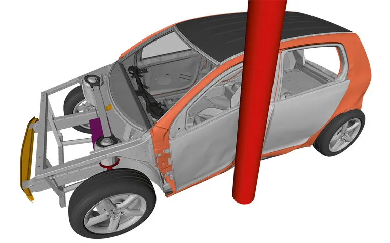
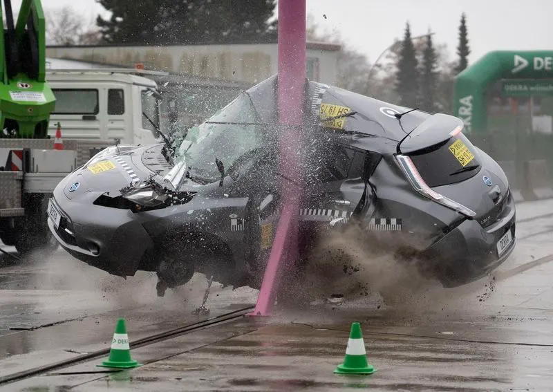
Objective:-
To perform frontal crash of the given car model with the given conditions and study the BIW model after crash.
Conditions :-
a. Check unit system and either follow [Mg mm s] or [Kg mm ms].
b. Create appropriate interface ,friction 0.2 and recommended parameters.
c. Make sure of no penetration and intersections.
d. Create rigid wall with friction 0.1 as per referance model.
e. Compare the model weight with the referance model and use added masses to reach target weight 700kg while getting CG about the required
range.
f. Initial velocity as shown in picture.
g. Use model checker to ensure good quality.
h. Timestep :0.5 to 0.1 microseconds.
i. Run 80ms.
Procedure:-
a. Check the unit system followed:-
1. Click on Cards>BEGIN CARD from model browser.
2. Check the entity editor in which unit system is used in this model.
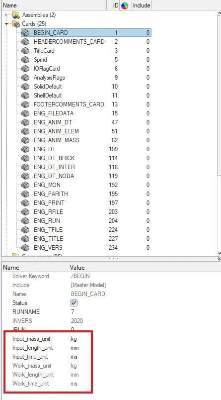
3. Here we use the units kg-mass, mm-length, ms-time.
b. Creating appropriate interfaces:-
1. We create a type 7 interface on the car body to study self intersection.
2. Right click on Groups in model browser> click on create.
3. In card image choose Type 7
4. Choose the slave nodes in Grnod_Id(S) and master elements in Surf_id(M).
5. Give value of friction as 0.2
6. Then fill the parameters with recommended parameters.
Recommended Parameters:-
Igap=2 :- Set variable gap to take into account the true distance between parts
Gapmin> 0.5mm :-Specify minimum thickness of the model to avoid numerical issues.
Inacti=6 :- Remove the initial penetrations where possible.
Istf=4 :- Set stiffness of interface based on the softer of master and slave.
Stmin=1 kN/mm :- Specify a minimum stiffness in the contact because of element deletion
Idel=2 :- Remove slave nodes from contact because of element deletion
Iform=2 :- Sliding forces are computed using stiffness parameters of the interface. Usually results in bigger time steps.
c. Check for penetrations and intersection :-
1. Its is to check these in hypercrash so we can also open hypercrash.
2. Import the model in hypercrash.
3. Go to Quality > Check all solver contact interfaces
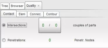
4. A quality tab appears and in that we can see that Intersection and penetration are zero.
d. Create rigid wall :-
1. For creating rigid wall in hypercrash we need to go to Loadcases > Rigid Wall.
2. Now a new module Rigid Wall appears near tree and other modules.
3. Right click on the Rigid wall browser area Create New > Rigid walls > Cylinder.
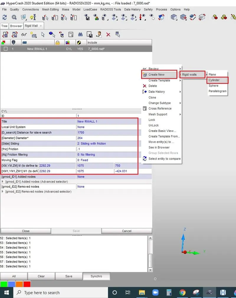
4. In title give a name.
5. Give a distance in distance for slave search.
6. Give the diameter of the pole in Diameter .
7. In Sliding change to 2.Sliding with friction.
8. For friction give value .1
9. In [XM,YM,ZM]M define the tail of the axis direction.
10. In [XM1,YM1,ZM1]M1 define the head of the axis direction.
11. Click on Save.
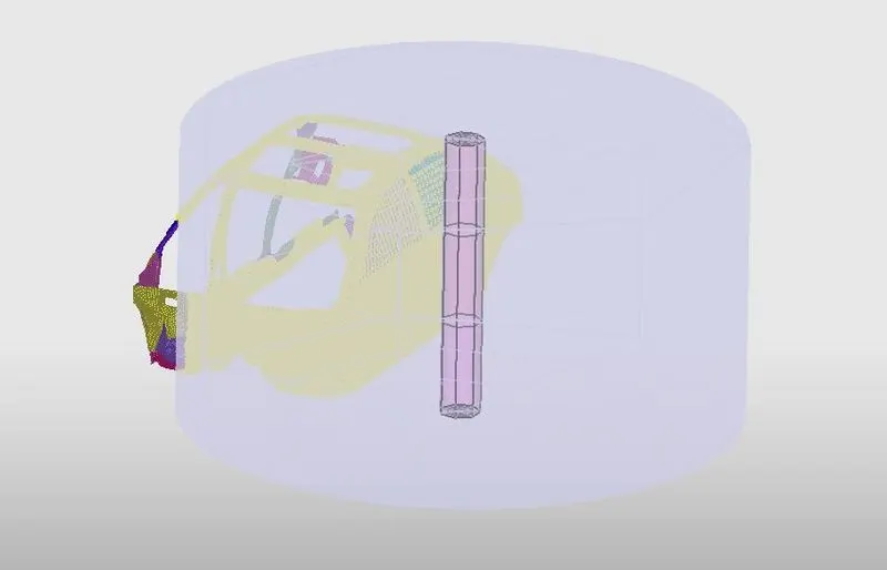
e. COG and Mass adjestment :-
1. To see the COG point go to Mass > Balanceing .
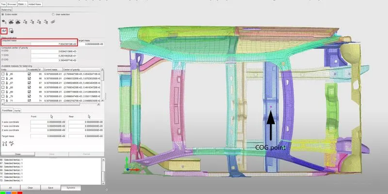
2. Click on the spectacle icon you can see the location of COG point now.
3. If it is not at the center, we need to shift it to the center. Also the total mass should be 700kg. The masses should be divided to different areas so that it should never exceed 700kg.
4. We can change the COG by adding Masses.
5. For adding mass go to LoadCases > Added Mass.
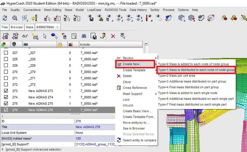
6. Right click on the Added mass area> Create New> Select Type 1- Mass is distributed to each of node group.
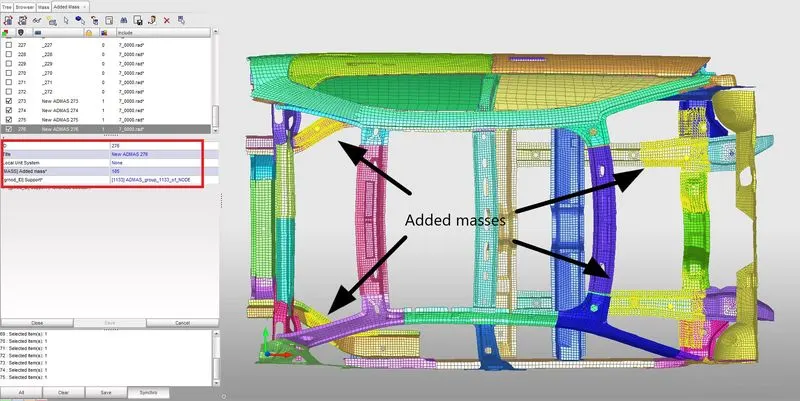
7. In title give a name.
8. In Added Mass give the mass to add.
9. In grnod_ID , pick the nodes to which the mass should be distributed.
10. Click on Save.
11. Like that add masses at different places of the car body and position the COG at center.
f. Give an Initial Velocity of 35mph (15.6464 m/s) :-
1. In browser tab Right Click > Creat New > I-L > Initial velocity.
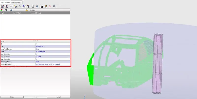
2. In the INVEL tab edit the values .
3. Type is translational because there is no rotation motion.
4. Only y velocity is given because there is only movement in the 7 direction.
5. In Grnod_id select the whole nodes of the car.
g. Check the model, eliminate errors and minimize warnings :-
1. To check the quality go to Hypermesh and Tools > Model Checker > Radioss Block
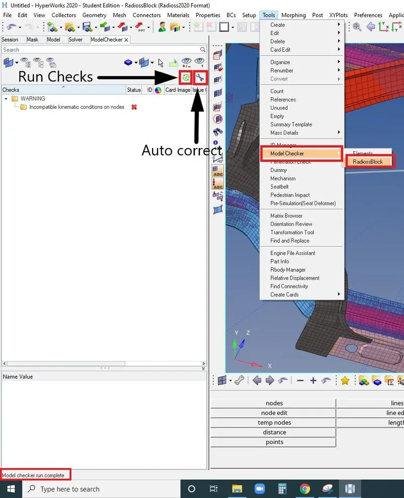
2. Click on Run Checks, When the check is finished it will be show on the bottom.
3. If we have errors Click on Auto Correct, it will eliminate almost most of the errors.
4. Still errors persist we need to look manually and correct it.
h. Give Time step and Run time :-
1. In Hypermesh from model browser choose Cards
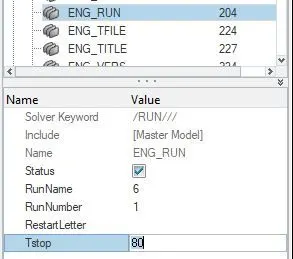
2. From cards open ENG_RUN
3. In that give the value of Tstop as 80.
4. To give the time step value open the ENG_DT card.
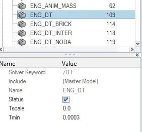
5. In that give the value .0003 for Tmin.
Output requests:
- Sectional force in the cross member.
- Intrusion at B pillar,hinge pillar and fuel tank region.Provide recommendation on what can help to reduce Fuel tank intrusion.
- Peak velocity of inner node of the door.
Procedure for creating Output requests :-
a. Creating Cross sections for cross members :-
1. For createing section we need to define skews so first we create skew.
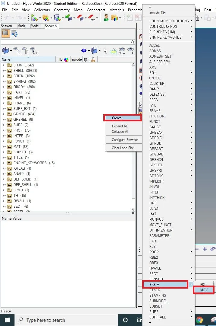
2. Go to solver tab Right click> Create > Skew > MOV
3. Then we need to select the nodes to define the planes for getting direction of the skew.
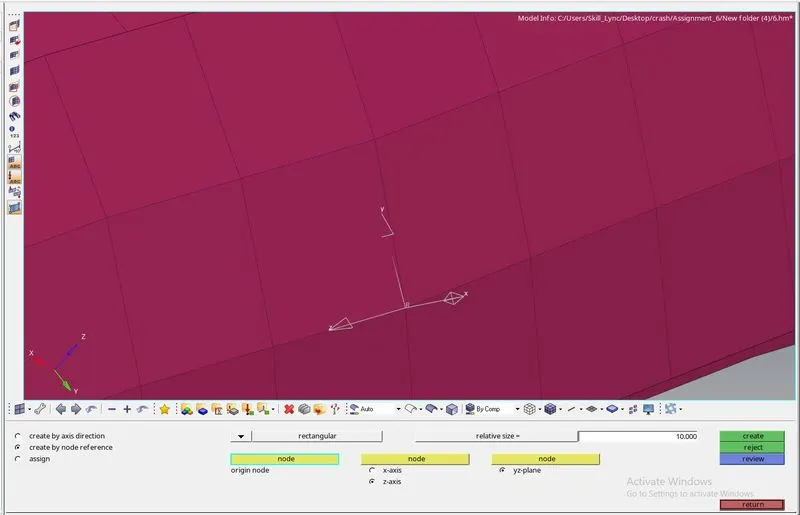
4. First select the node to show origin, then choose an axis and select the nodes to define a plane.
5. Click on create.
6. Now we can create a section. Go to model tab Right click > Create > Cross section.
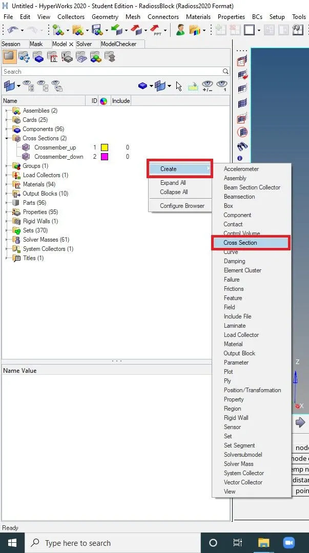
7. In the Entity editor Give the parameters correctly.
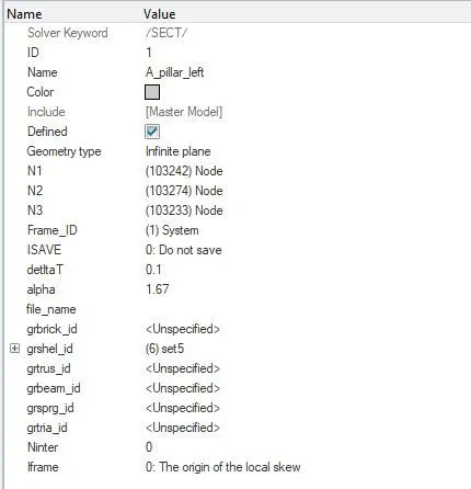
8. Give a Name to the crosection.
9. Select 3 nodes to define the x-axis and x-y plane.
10. In Frame_ID select the skew that we created.
11. In deltaT give .1 and for alpha give 1.67
12. In grshel_id select the set of elements. Where we want to see the section force.
13. Like this we need to create sections and skews in 2 Cross beams.
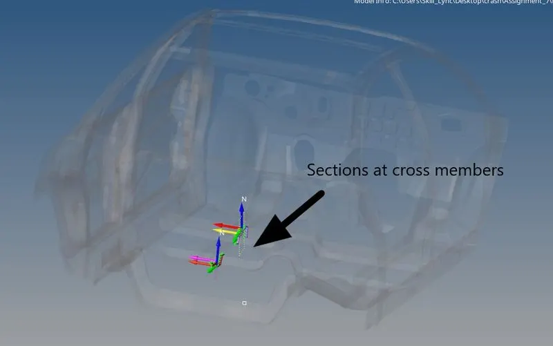
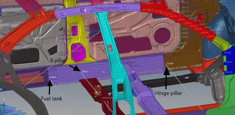
b. Intrusion at B pillar,hinge pillar and fuel tank region :-
1. Intrution is measured using 2 spring from each node at B pillar, hinge pillar and fuel tank region.
2. For creating spring we go to 1D > springs > select the nodes between where we want to create the spring.
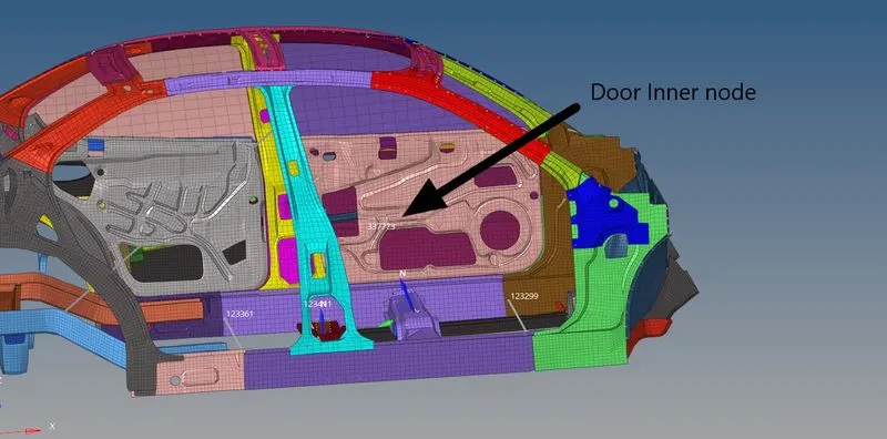
c. Peak velocity of inner node of the door :-
1. Peak velocity can be identifying by ploting TH for the inner node of the door.
2. Go to solver tab.
3. Right click on TH> NODE.
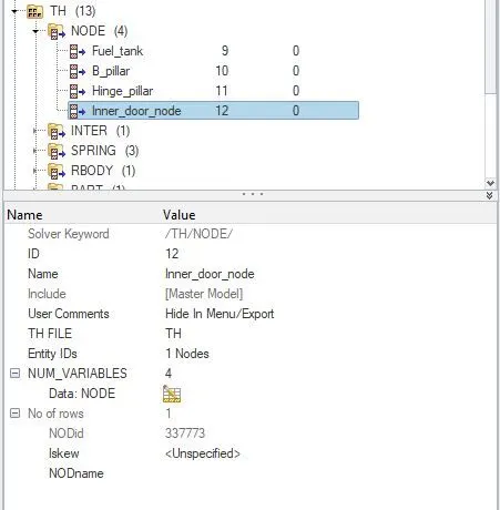
4. In entity editor select the node of which we need to see the peak velocity.
5. In NUM_VARIABLES select number of variables (How many forces you need to plot in y axis)
6. In Data:NODE select which all forces you need to plot.
d. For ploting graphs, add TH as required :-
1. Go to solver tab.
2. Right click on TH, Select option as we needed.
INTER- Interfaces
ACCEL- Acceleration
SPRING- spring elongation
PART- For each parts forces
SECTIO- sectional forces
3. First we select SECTIO for ploting forces.
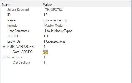
4. In Entity ID select the Cross sections of which we need to plot the graph.
5. In NUM_VARIABLES select number of variables (How many forces you need to plot in y axis)
6. In Data:SECTIO select which all forces you need to plot.
7. Like this create TH of SPRING, PART, INTER ... etc
RESULTS :-
Simulation Explanation :-
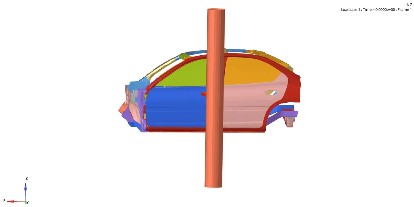
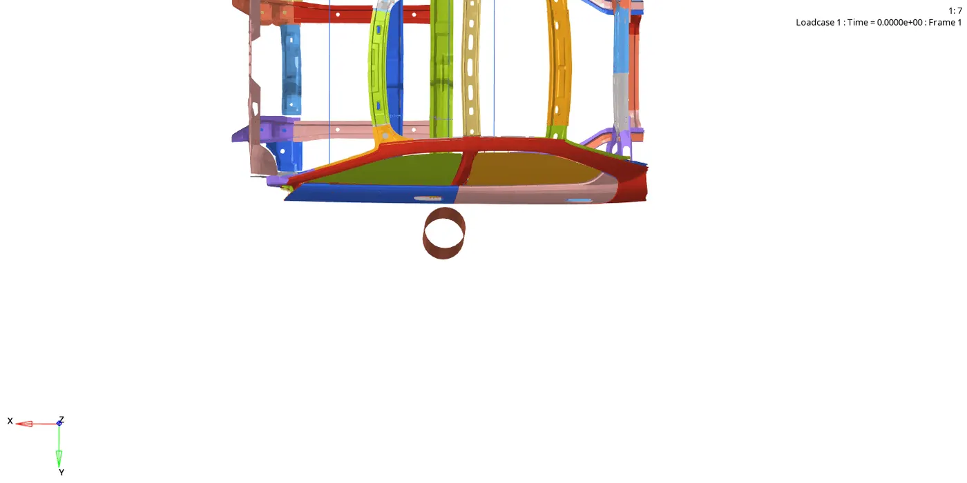
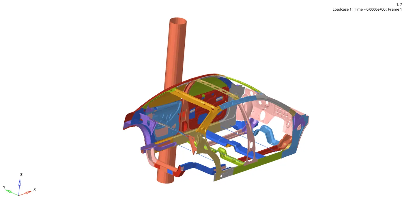
Here the side of the car is crashing towards a rigid pole. When the B Pillar hits the pole its movement is almost arrested but the front and back side will keep on moving for a bit. Initially the car will be having a velocity of 15.6464m/s, then it will come to rest as it hit the pole.
Energy Graph :-
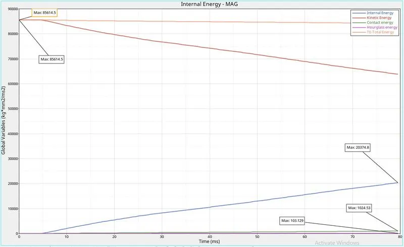
For the car components, we used Ishell=24 QEPH formulation so only a small presence of the Hourglass energy is present,like 103.129J . The contact energy is formed only when there is penetration, at the begining there is no penetration. But at the end there is some penetration so some contact energy is created and that too 1024.53J which is soo small compare to other energies . Initially the K.E energy is high, which is 85614.5J and will reduce as the car moves and get crushed. The K.E energy is absorbed by the car and deformations occur. So the kinetic energy is converted to internal energy . That is why when we look at K.E and internal energy graphs we can see that the reduction in kinetic energy curve is just the opposite of increasing internal energy curve. The total energy is the sum of all energy so the curve is like a straight line.
Sectional force at the cross members:-
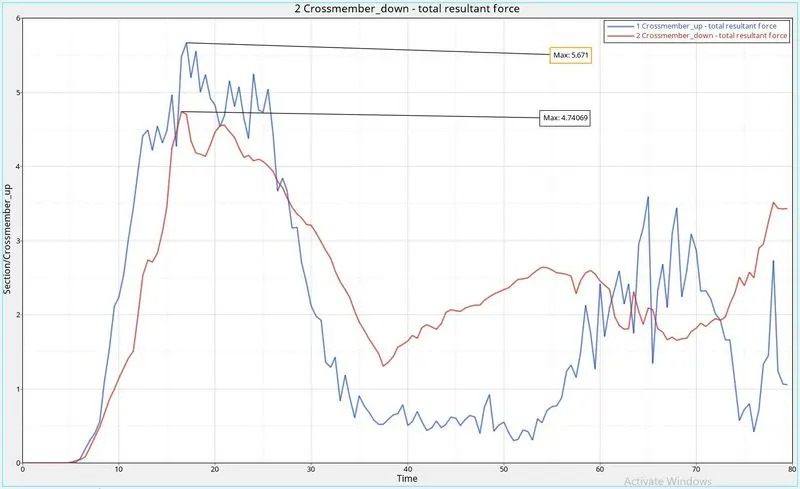
The cross members are the parts which transfer the force from one side to other parts when the impact occurs. The max section force at the cross memebr 1 is 5.671kN and for cross member 2 is 4.74069kN. When the car hits the rigid pole the force is transfered from the B pillar to cross memebrs and then to the other side. In the graph first we can see a hike in curves this is due to the force acting on the cross members axially, due to this force the cross members get bended and the force passing through the cross members get reduced. That is why we see the drop in resultant force in the graph. Eventhough it drops, it wont come to zero , in the animation we can see that the bended cross members again gets deformed soo the curves moves in a range between .5 - 3.5 kN.
Intrusion at B pillar,hinge pillar and fuel tank region:-
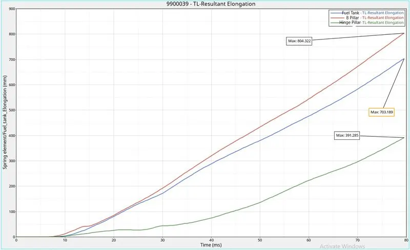
Intrusions are one of the important parameter, while checking the passenger saftey in crash. To know the intrusions at fuel tank, B Pillar and Hinge Pillar we have placed a spring in these region. From the elongation of the spring we can understand how much intrusion is happend in these regions. Here in this graph we can see that the B pillar have the maximum intrusion, then come the fuel tank and least intrusion is seen at the hinge pillar . So to reduce the fuel tank intrusion we should add one more cross member at the position of fuel tank. Here at the B-Pillar, the spring set there is having an elongation 804mm .The B-pillar touches the rigid pole and the other side is crushed towards it, so its intrusion is soo high. For the Fuel tank , the spring there shows an elongation of 703.189mm. And for the Hinge Pillar it shows an elongation of 391.285mm.
Peak velocity of inner node of the door :-
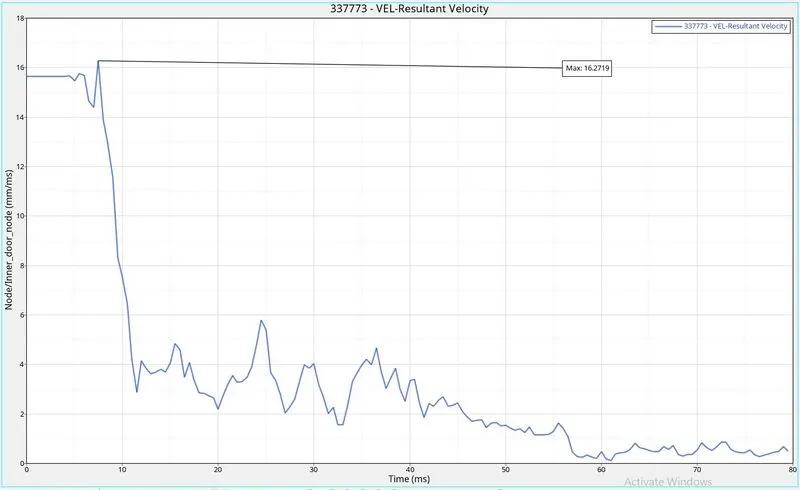
Initial velocity of the car is 15.6464m/s but when the car hits suddenly on the pole, velocity slightly increases to 16.2719m/s and then decreases .
Von Mises Animation :-
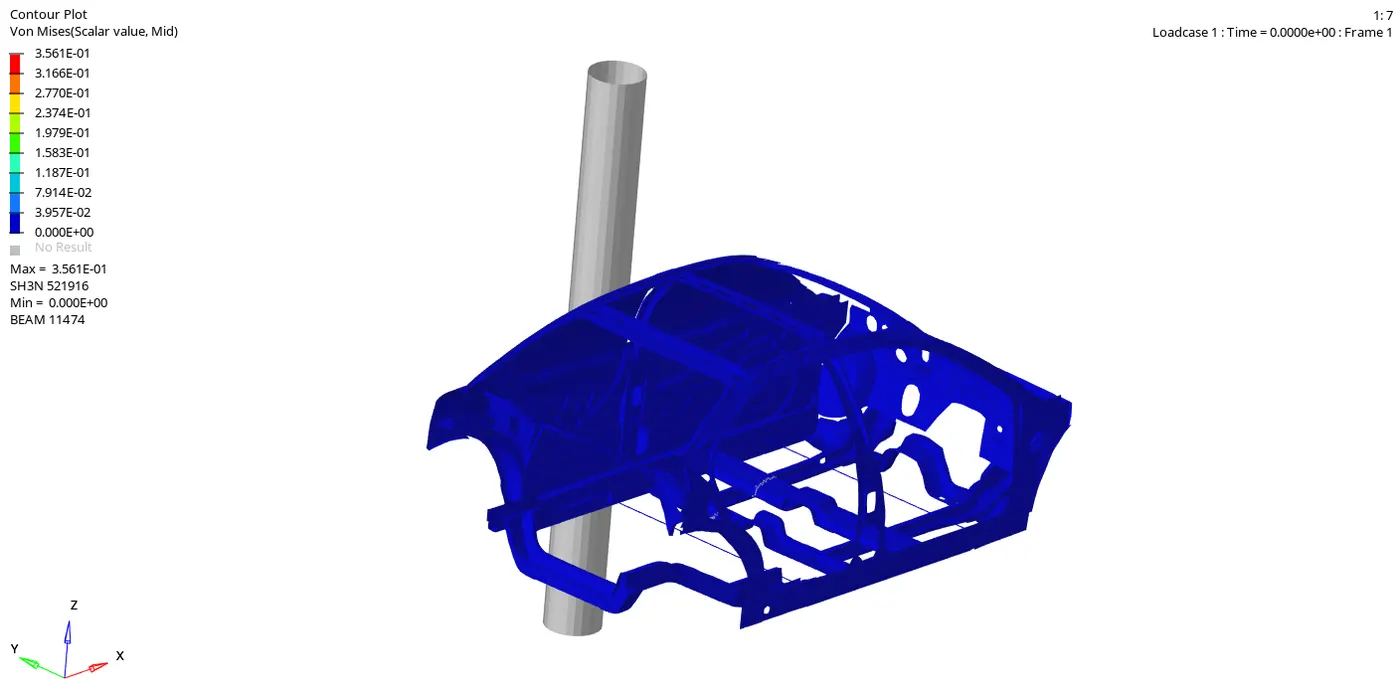
In the Von mises we can see the stress formed on the car during the crash. Here the maximum stress formed is 3.561E-01 and that too is at the cross members. We can see that the one side of the crossmember is hitting the pole first and throughout the simulation it is getting crushed.
Conclusion :-
To know the saftey of the passengers of a car, side car crash test is very important. Here we have done the same by hitting the car to a rigid pole. We applied boundary condition to the cars parts and an initial velocity is given. Then when we run the simulation we can see which all parts are affected in the crash, how much each part get deformed, Intrusion of part into the passenger cabin area and all. After under standing these we will get to know what all things we should do on this car to make it more safe. example to decrease the amount of intrusion in the Fuel tank region we can introduce a cross member there.