Assignment 5
Objective:-
Part 1 :- Mesh the bumber assembly model with Element target size as 6mm.
Part 2 :- Run the Crash tube model with 6 different cases as given below and compare.
1.Run the crash tube model as it is.
2. Change the Inacti=6 and run.
3. Create the type 11 contact and run.
4. Remove both notches and remove boundary condition on rigid body node then run.
5. Create a new notch in the middle ,select the whole section and run.
6. Create a new notch with nodes only from opposing 2 faces and run.
Procedure :-
Part 1:- Meshing bumber assembly
1. Import the model to hypermesh file. File> Open> Model> Choose the file from list> Open.
2. Change to By topo view to find the deformation or errors while importing.
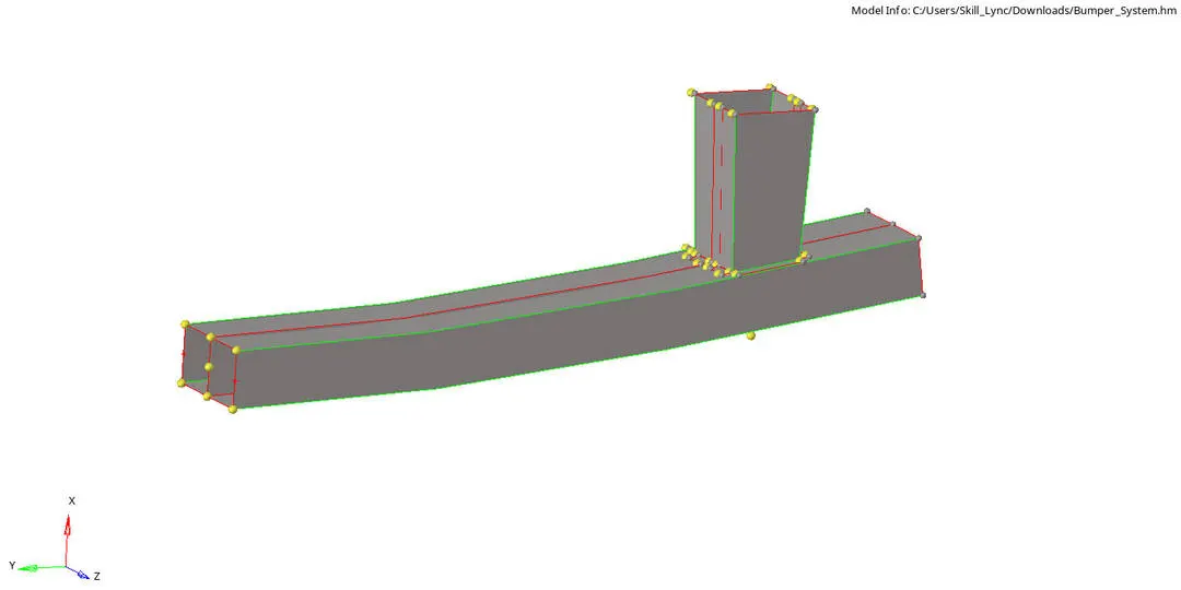
3. We can see some errors in connection of edges.
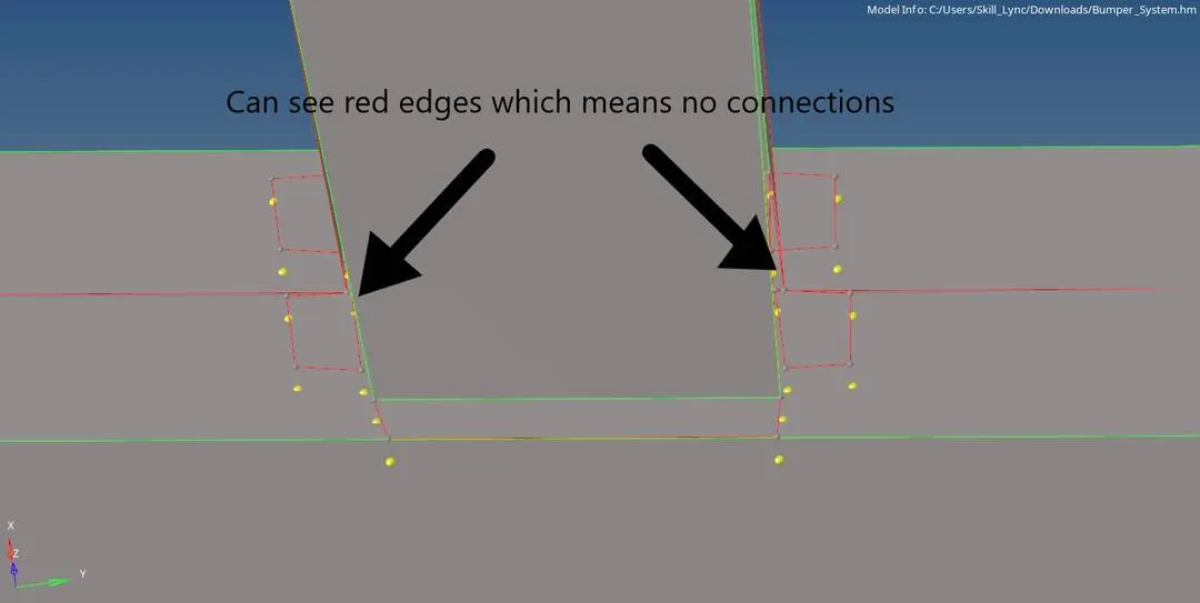
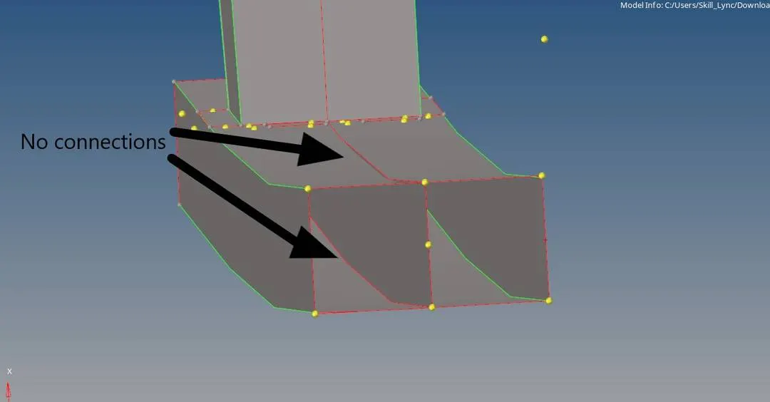
4. So we do a cleanup of this model.
5. We use Translate (Shift+F4). Choose surface and click on the surface to move . Align the surface with the nearest edge.
6. Then use Geometry > Quick edit> Toggle edge. Or use Geometry> Edge edit>Replace.
7.Also for connecting the middle surface use Geometry> Surface Edit> Extend.
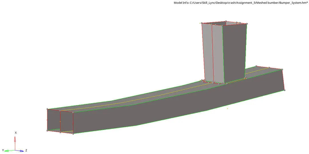
8. For meshing press F12, give element size as 6. Click on surface to mesh . Click on Mesh.
9.After meshing give connections between parts by going to 1D> Rigids> Select the Dof's needed> Click on Create.
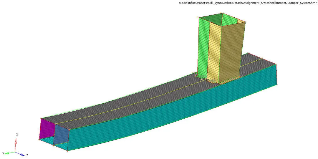
Part 2 :-
Interfaces or contacts are defined to model how parts interact when they come into contact with each other.
The penalty method treats the behaviour between slave nodes and master segments as springs that generate resistive forces as a funtion of penetration. If the slave nodes comes into the gap of the master nodes this spring element will push the slave node to the outer of the gap.
Most widely used contact algorithms are:-
1. Type 7, variable stiffness, node to surface contact.
2. Type 11, variable stiffness, edge to edge contact.
Important Interface parameter:-
Igap:- Determines how the size of the gap is calculated.
Gapmin:- Minimum gap for activation of interface.
Inacti :- Action to take if initial penitrations exist.
Istif :- Affects how the stiffness of the interface is calculated.
Iform:- Friction formulation.
Stmin:- Minimum stiffness to use in the interface.
Idel:- What to do with slave nodes and master segments if elements fail (deleted) that they are attached to.
Recommended Parameters:-
Igap=2 :- Set variable gap to take into account the true distance between parts
Gapmin> 0.5mm :-Specify minimum thickness of the model to avoid numerical issues.
Inacti=6 :- Remove the initial penetrations where possible.
Istf=4 :- Set stiffness of interface based on the softer of master and slave.
Stmin=1000N/mm :- Specify a minimum stiffness in the contact because of element deletion
Idel=2 :- Remove slave nodes from contact because of element deletion
Iform=2 :- Sliding forces are computed using stiffness parameters of the interface. Usually results in bigger time steps.
Case1:- Run the crash tube model as it is.
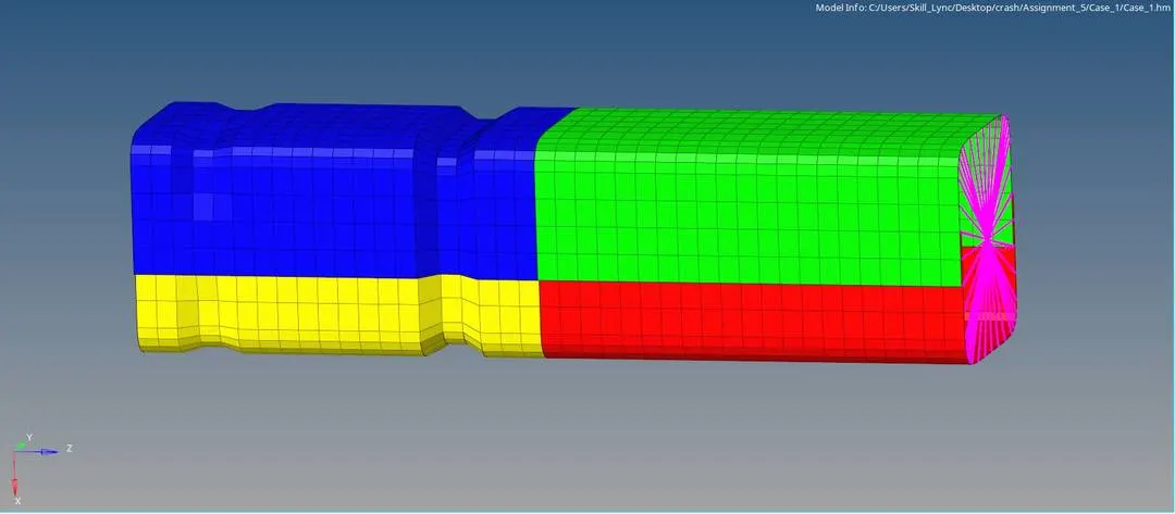
In this case we are going to run the model as it is, the parameters that we applied are given below.
Igap=0, So the gap will be constant and Gap is defined by Gapmin.
Gapmin=1
We can see that the total distance between the master and slave are 2.1mm and Gapmin=1. So master have 1mm gap and slave have 1mm gap as the Igap=0, even after adding them it will be 2mm only so there is no initial penetration in this case.
Inacti=0, No action is taken when it is zero.
Istif=4, Interface stiffness is computed using both master and slave characteristics
Iform=2, Stiffness formulation is done, sliding force are computed using stiffness parameters of the interface
Stmin=1
Idel=0, No update ; the master and free nodes are kept and may lead to instability
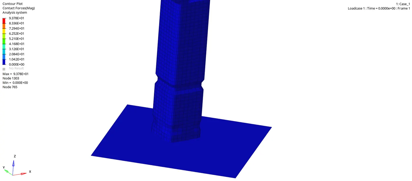
From the simulation we can see that after 1st crush when the end elements reach the bottom, the elements are being crushed again. At the time of 1st crush there was only a littile bit of penetration happend and littile contact force is applied on the slave. But when the 2nd crushing is happening more slaves try to penetrate into the master, so we can see more contact force in the second crushing.
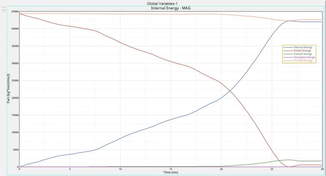
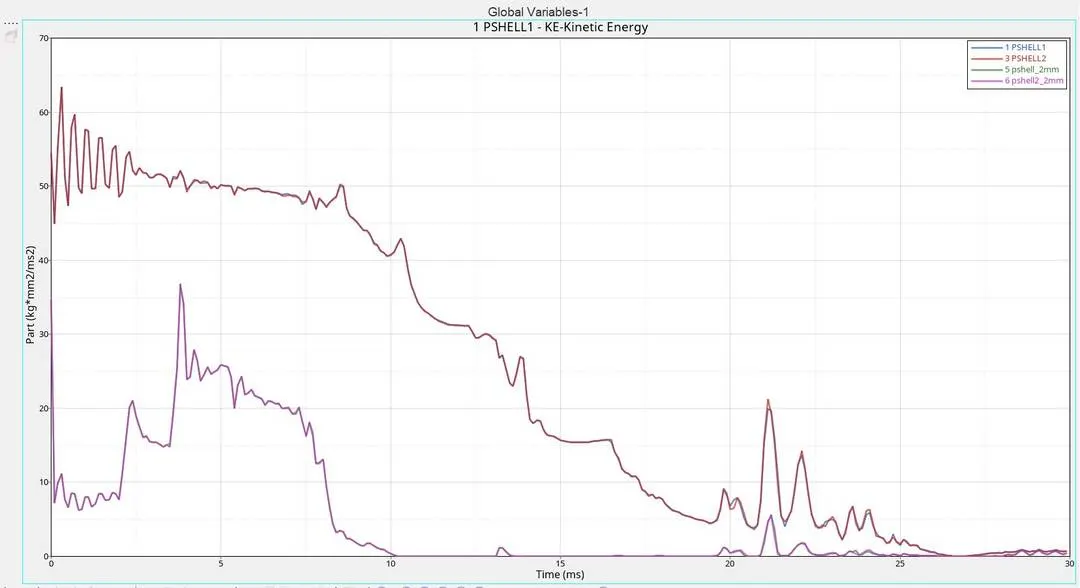
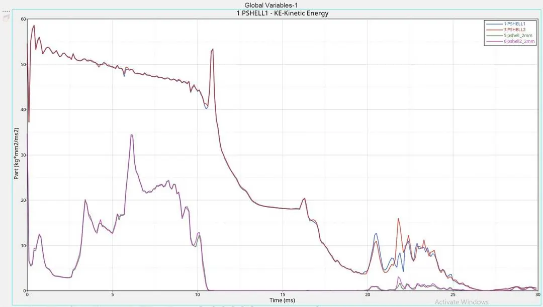
* From energy graph we can see that the K.E is initially at its max value and as the elements crushed against the wall the deformation is happened and the kinetic energy is reduced gragually. But at the end we can see that K.E after reaching zero increases a little bit, This is because in simulation we can see that after fully crushing against the wall the elements move back a little bit like a spring.
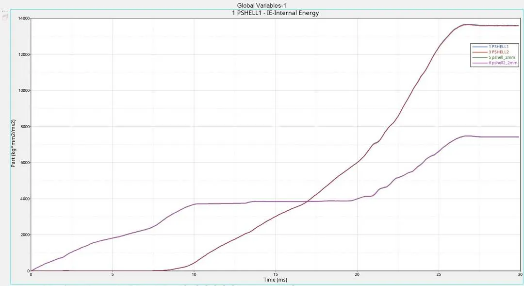
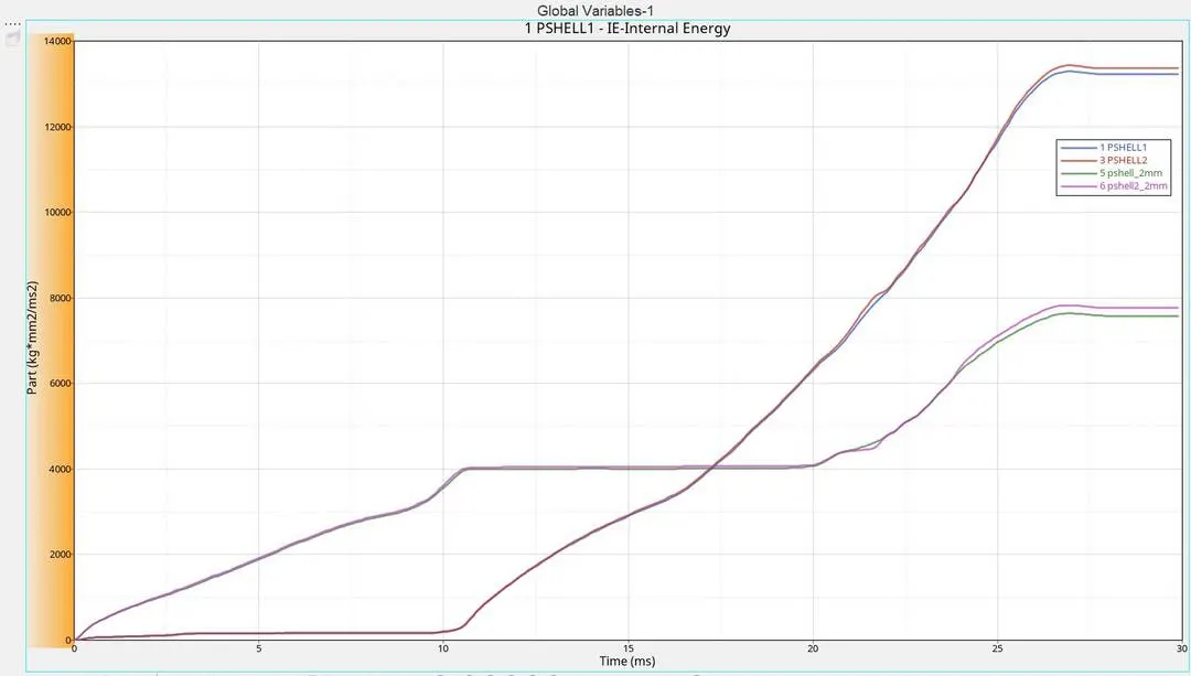
* The K.E is abosrbed by the deformation, this means that the K.E is converted into Internal energy. Thats why the internal energy is increasing as the kinetic energy decreasing. (Energy cannot be created nor destroyed, it can only be converted from one form to another)
* The contact energy is formed only when there is penetration. At the begining there is no penetration. But at the end there is some penetration so some contact energy is created.
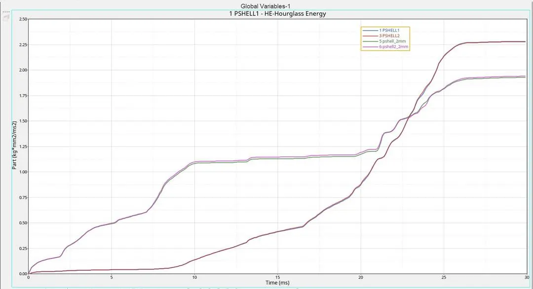
* The hourglass energy is zero, because we use Ishell value 24 QEPH.
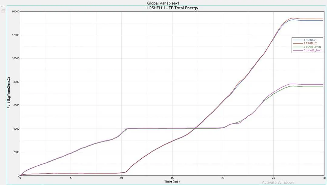
* Total energy is the sum of all energies so it is have this pattern.
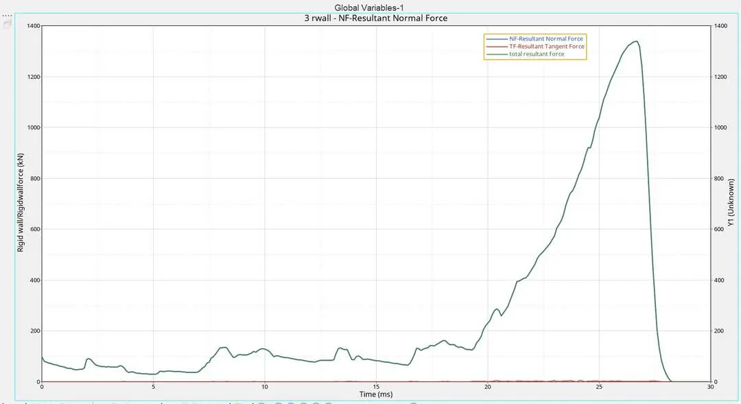
* As the force is applied on the rigid body we can see that for the 1st crushing the normal force is within a range of 200KN. And for the second crushing the normal force suddenly increases to a maximum of 1337.9KN. More force is applied on the rigid body at the 2nd crushing.
* The frictional force is only just 5.28KN. because there is no frictional force at the beganing and at the end while the 2nd crushing is happening some frictional force appeares
TH/Part :-
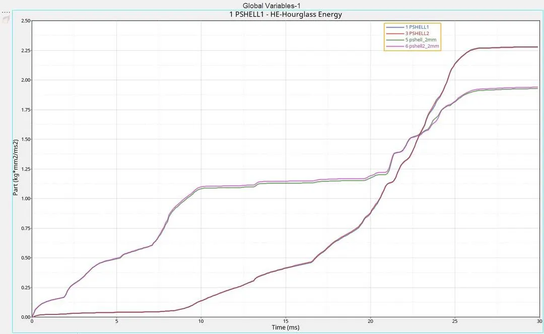
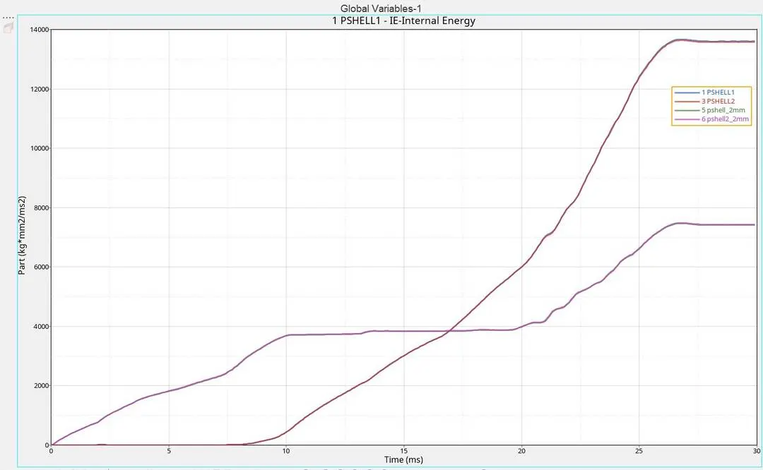
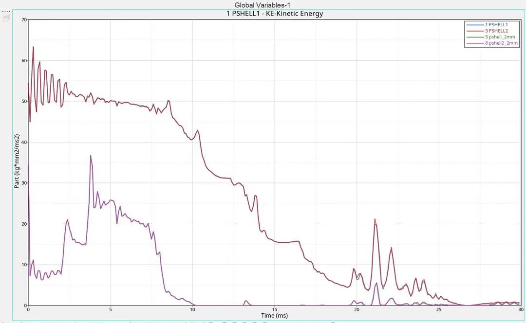
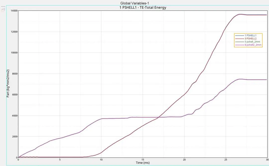
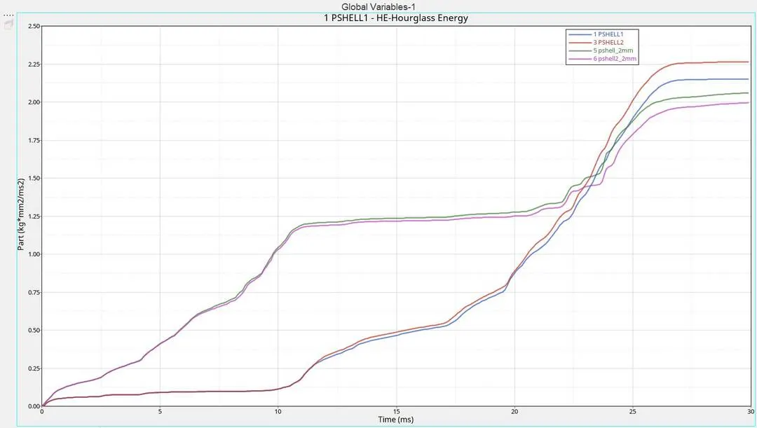
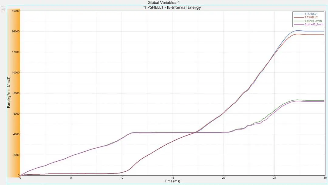
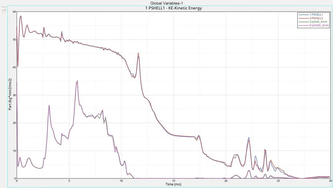
* TH/Part of each components is ploted against energies.
* I plot 4 components against one energy so that we can study the differents in each components with same energy
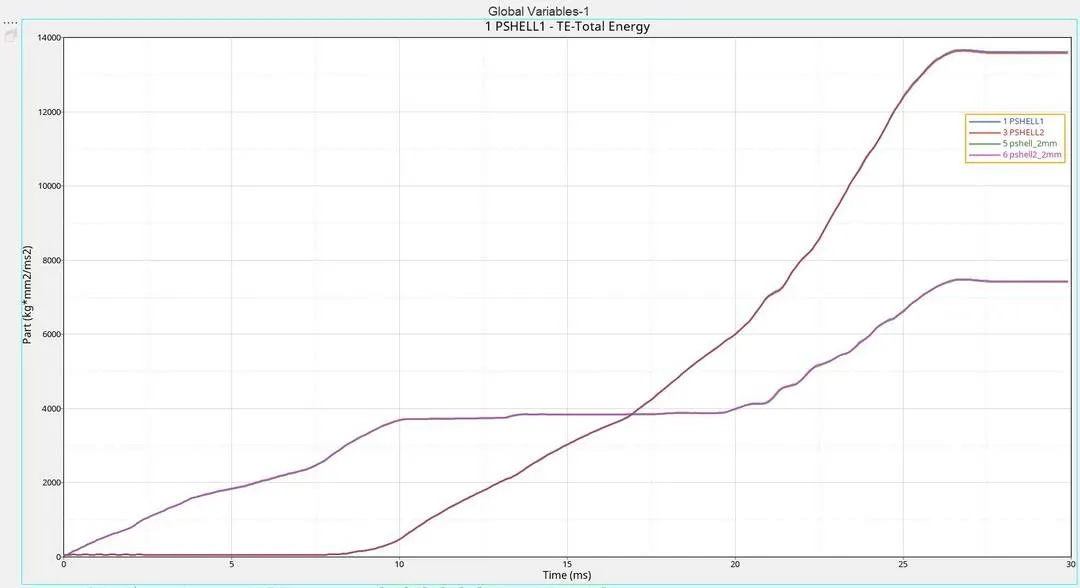
Case 2:- Change the Inacti=6 and run.
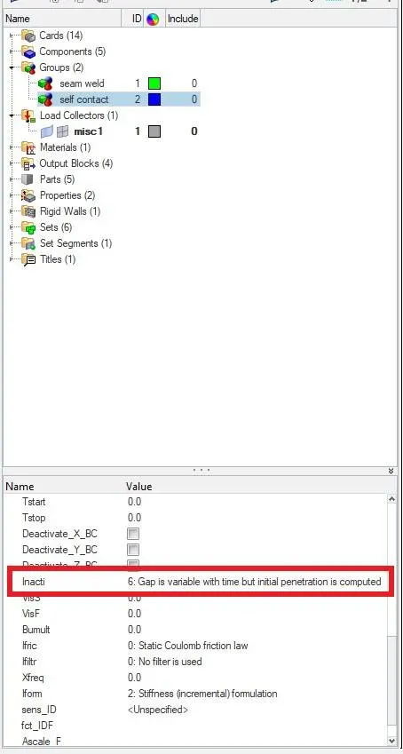
* In this case the only change that we made is, Changed the value of Inacti=6
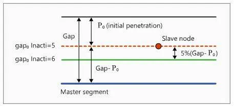
* If we use inacti=6, The gap defined will be changed . The new gap will be 5% of the difference between the total gap and initial penetration(Po).
* In inacti=6 the gap is reduced and scaled, this value is the recommended value and is more accurate.
* When we checked the simulation, energy graph and force graph, it is seen that there is no difference in any of the values. This is because the only change that we made is in inacti value. Inacti value is only affected to the initial penetration. In this case too there is no initial penetration. So inacti=6 is not applied here. thus no change in values.
* Igap=0 and Gapmin=1. The slave and master is having a distance 2.1 between which is above the required gap , so no initial penetration is occured.
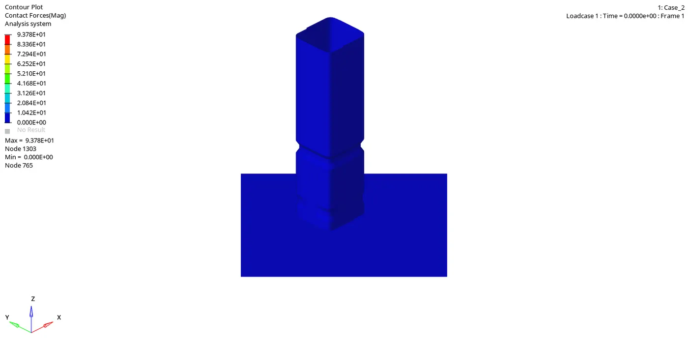
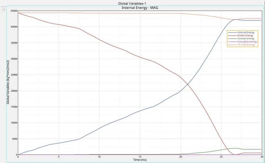
* From energy graph we can see that the K.E is initially at its max value and as the elements crushed against the wall the deformation is happened and the kinetic energy is reduced gragually. But at the end we can see that K.E after reaching zero increases a little bit, This is because in simulation we can see that after fully crushing against the wall the elements move back a little bit like a spring.
* The K.E is abosrbed by the deformation, this means that the K.E is converted into Internal energy. Thats why the internal energy is increasing as the kinetic energy decreasing. (Energy cannot be created nor destroyed, it can only be converted from one form to another)
* The contact energy is formed only when there is penetration. At the begining there is no penetration. But at the end there is some penetration so some contact energy is created.
* The hourglass energy is zero, because we use Ishell value 24 QEPH.
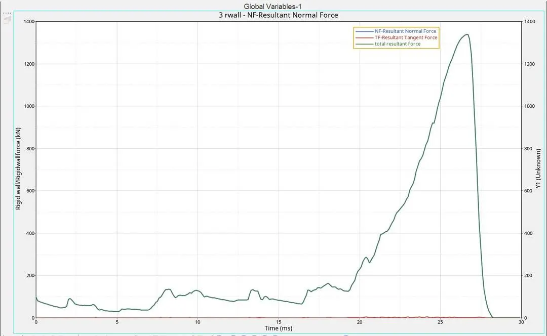
* As the force is applied on the rigid body we can see that for the 1st crushing the normal force is within a range of 200KN. And for the second crushing the normal force suddenly increases to a maximum of 1337.9KN. More force is applied on the rigid body at the 2nd crushing.
* The frictional force is only just 5.28kN. because there is no frictional force at the beganing and at the end while the 2nd crushing is happening some frictional force appeares.
TH/Part is ploted:-
Case 3:- Create the type 11 contact and run.
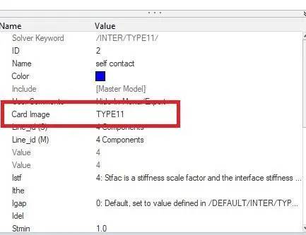
*In this we need to create a type 11 contact card.
1. Click on groups in model browser.
2. Right click and choose contact.
3. Change the card image to Type11.
4. Choose the components.
5. Give recommended parameter values.
6. Save the model.
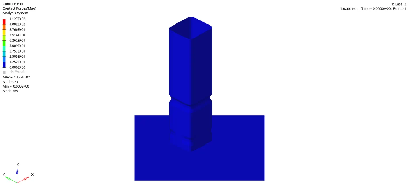
In this simulation type 11 is used, Which is edge to edge contact. Type 11 interface can be added to capture the physics correctly. This type is defined by identifying master and slave lines.
In type 7 we could see some penetrations are happening even when the gap conditions are satisfied. so we use type 11 for correctly getting the penetrations. As this type is based on edges. No penetrations can pass without knowing.
Also we could see that a small increase in the contact force in this case than the others because some penetrations which are not caught by the type 7 is noted in the type 11.
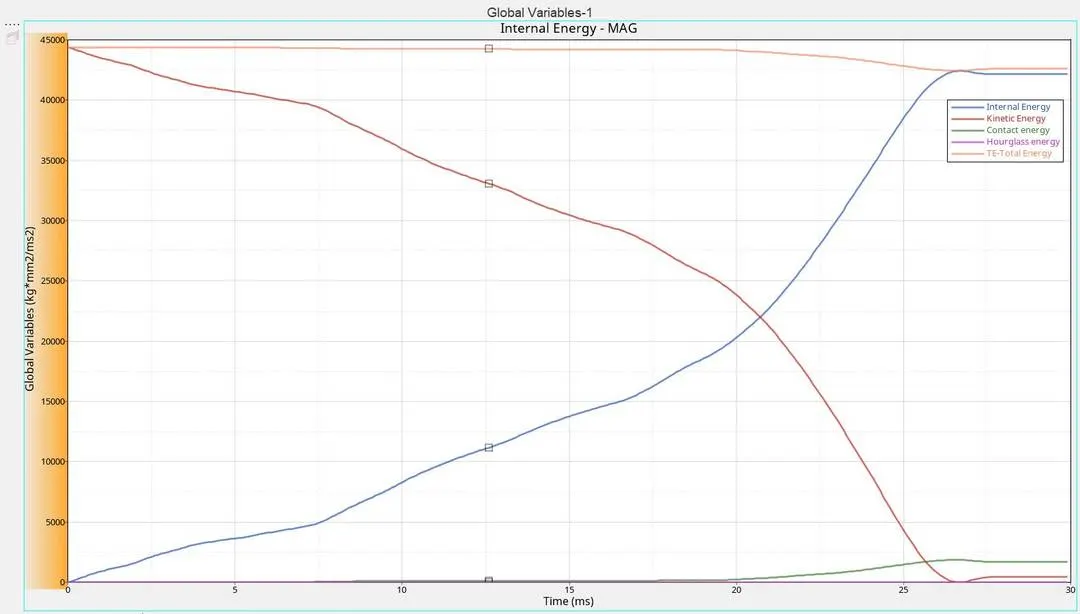
* In energy graph we cant see much of a difference
* Internal energy is increasing as the K.E is decreasing.
* Contact energy increases as the penetration happens
* zero Hourglass energy due to use of QEPH.
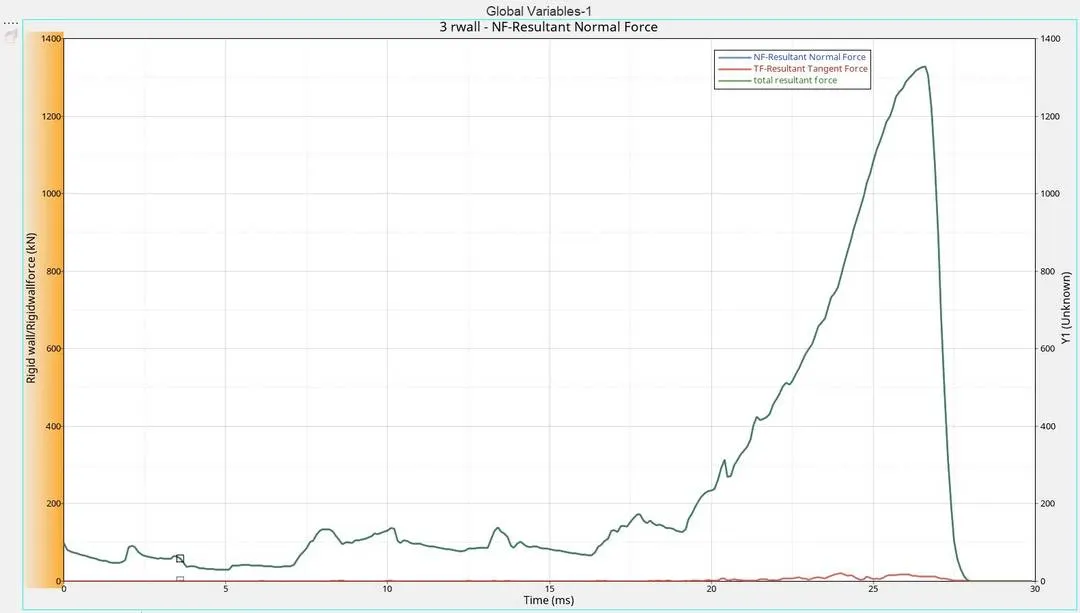
* Normal forces increases as the crushing proceeds. At the 1st crushing normal force is less but it suddenly increases as the 2nd crush take place.
*When the 2nd crushing take place frictional force is also produced.
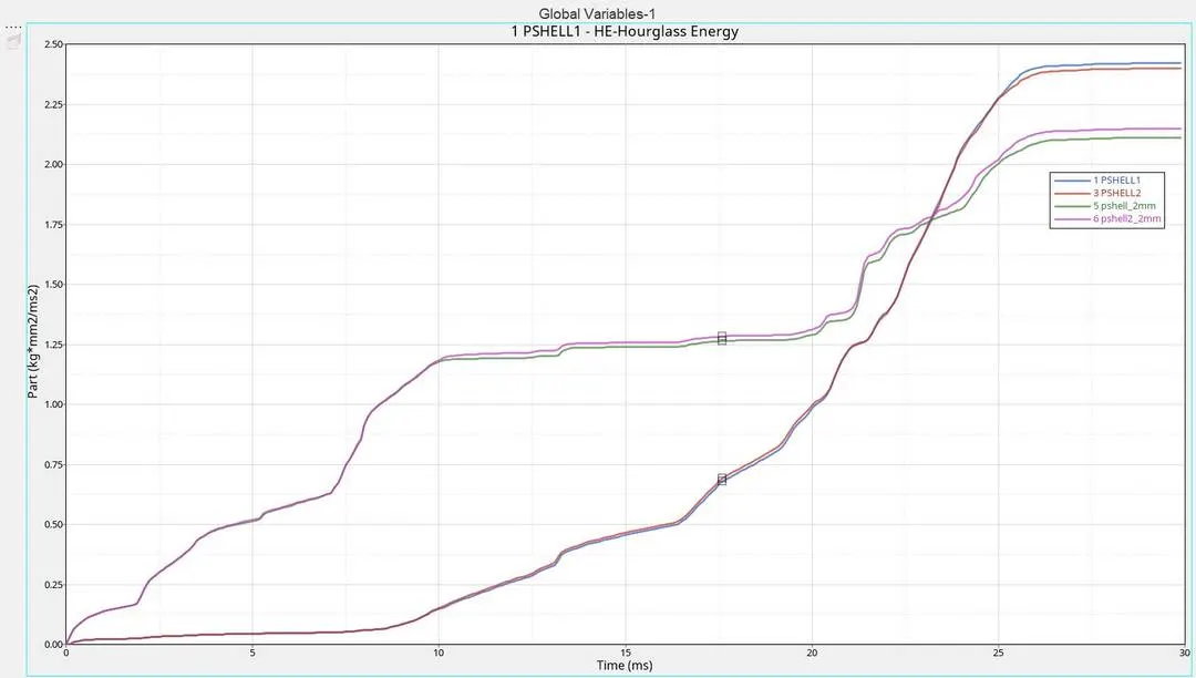
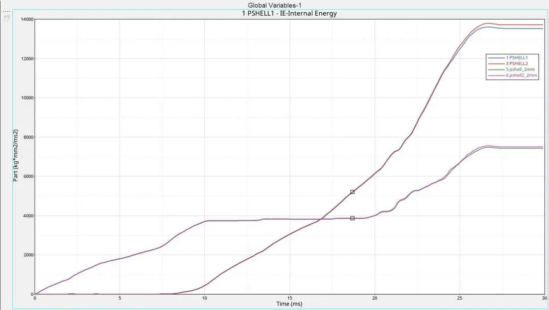
*TH/PART is ploted:-
Case 4 :- Remove both notches and remove boundary condition on rigid body node then run.
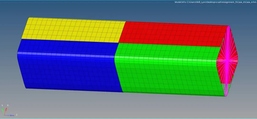
* First we need to remove all the notches from the model
* I have used Align tool (F7) for this operation.
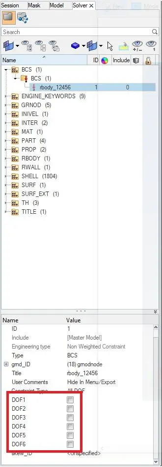
* After removing the notches i have removed all the boundary conditions.
* By going to the solver browser and Click on BCS.
*Then uncheck the DOFs in entity editor to remove the boundary conditions.
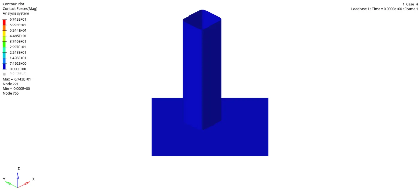
* Here we can see that the contact force is reduced when the notch is removed.
* Here there is only 6.743E+01N as maximum Contact force. Almost half of the contact force in other cases.
* Also when the notch was present the deformation will start just below the notch part.
* But here the deformation start from the bottom part.
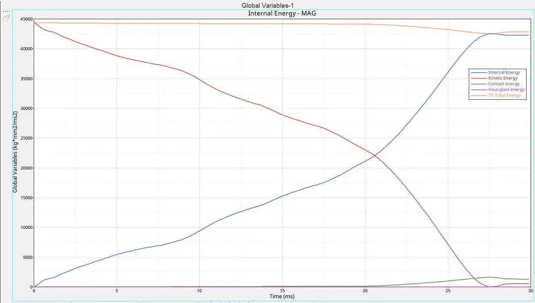
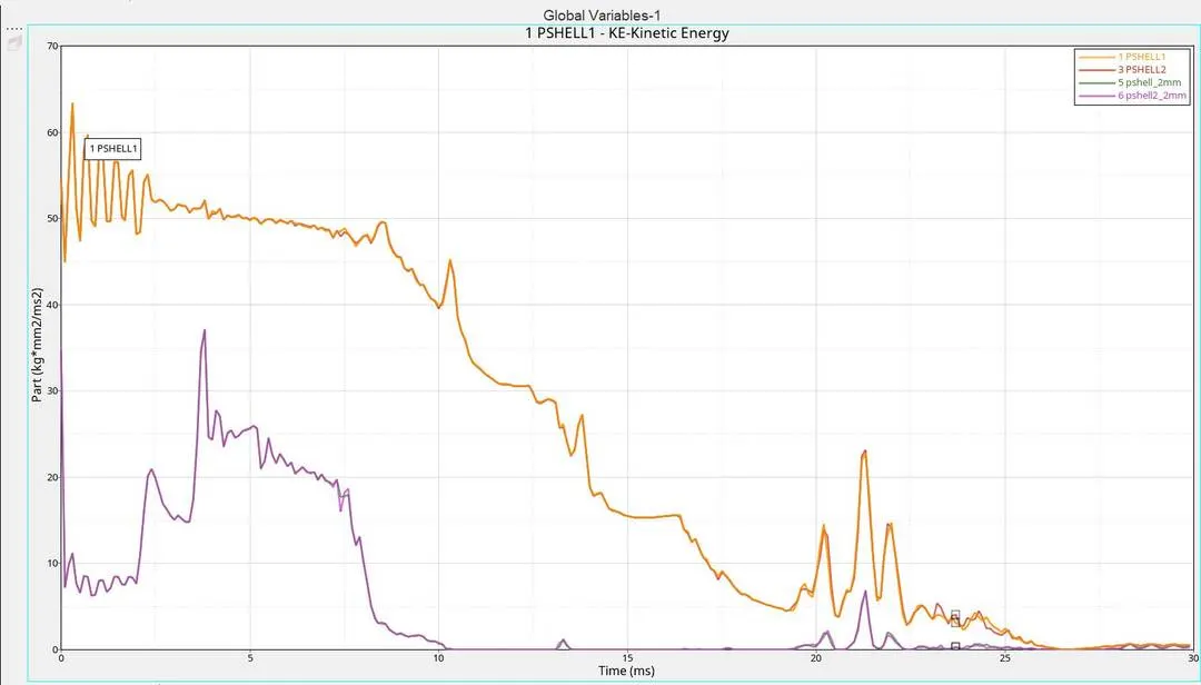
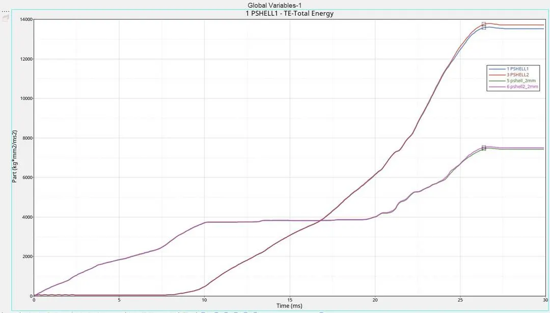
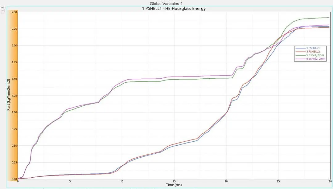
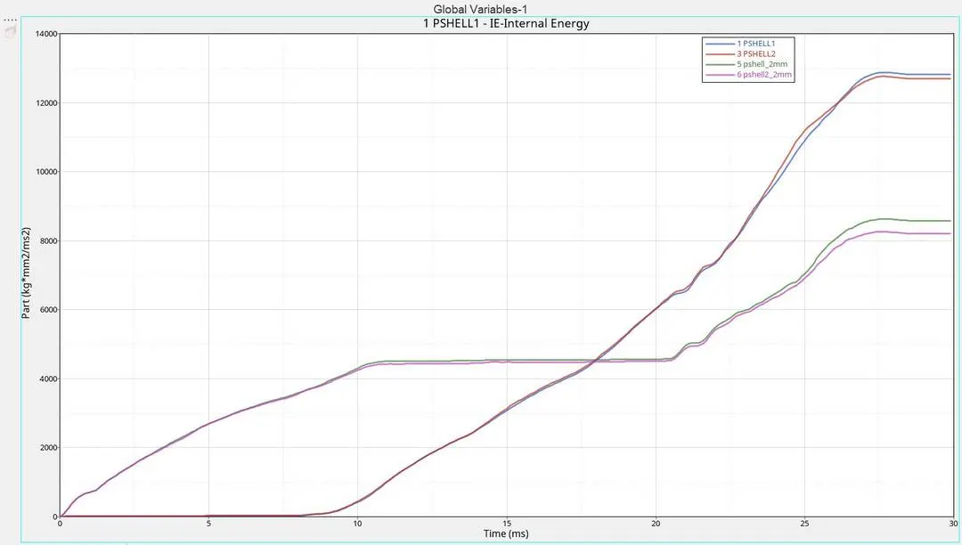
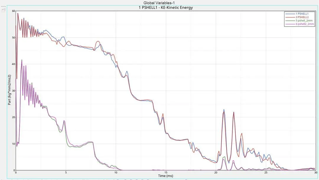
* In energy graph we cant see much of a difference
* Internal energy is increasing as the K.E is decreasing.
* Contact energy increases as the penetration happens. But contact energy is lesser than in other cases.
* zero Hourglass energy due to use of QEPH.
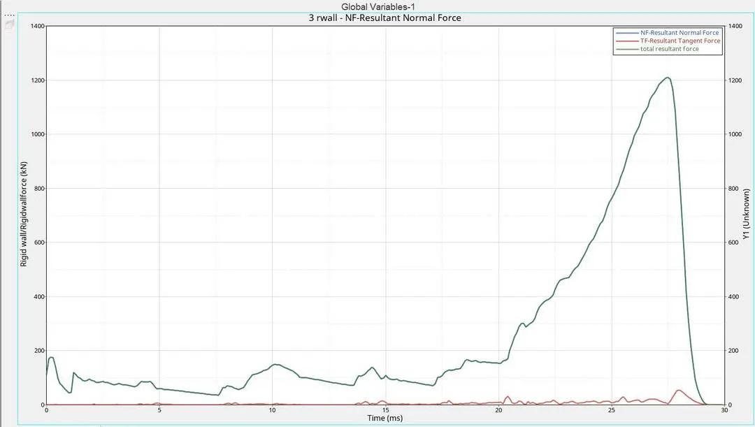
* Normal forces increases as the crushing proceeds. At the 1st crushing normal force is less but it suddenly increases as the 2nd crush take place.
* Here we can see that the Max. normal load is 1209.14kN which is the lowest Max normal in the 6 cases
*When the 2nd crushing take place, frictional force is also produced.
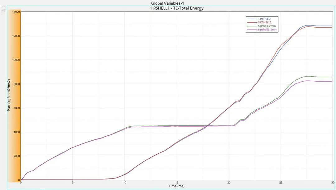
TH/PART is ploted:-
Case 5 :- Create a new notch in the middle ,select the whole section and run.
* In order to make a notch at the middle we can you Translate (Shift+F4) option.
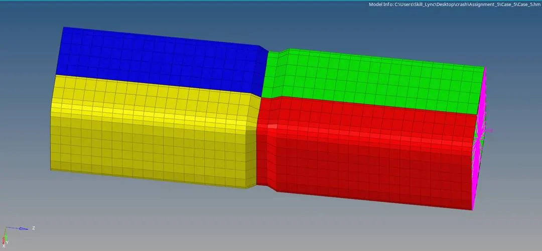
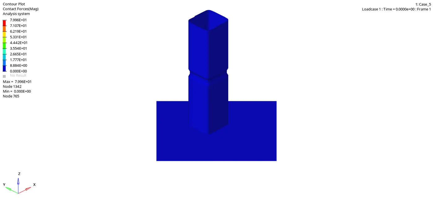
* As the notch is introduced again we can see that the deformation is formed at the notch part.
* Also due to the presents of notch we can see that the contact energy is increaseing again.
* But here there is only one notch so that even if the contact energy increases it is not much as the 1st and 2nd cases.
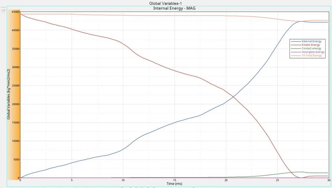
* The K.E is decresing and we can see that the internal energy is increasing.
* As the notch appears again the contact energy is slightly increasing again.
*Hourglass is still zero due to Ishell 24.
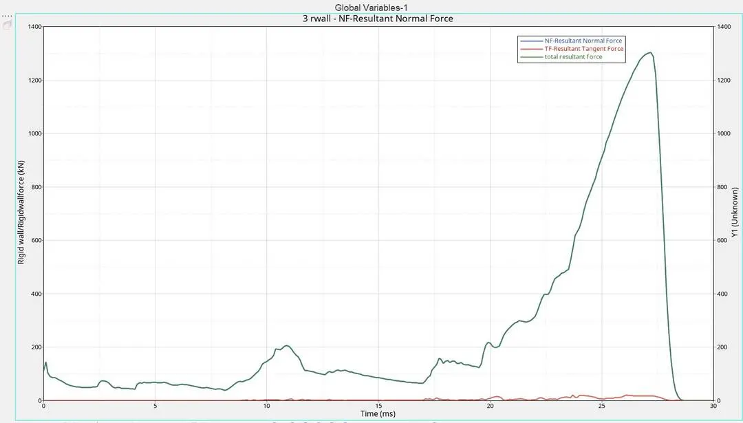
* We have seen that when the notch is removed the normal force was reduced but when it is introduced again the normal forces also increased.
* Here we have a max normal force of 1303.02 kN.
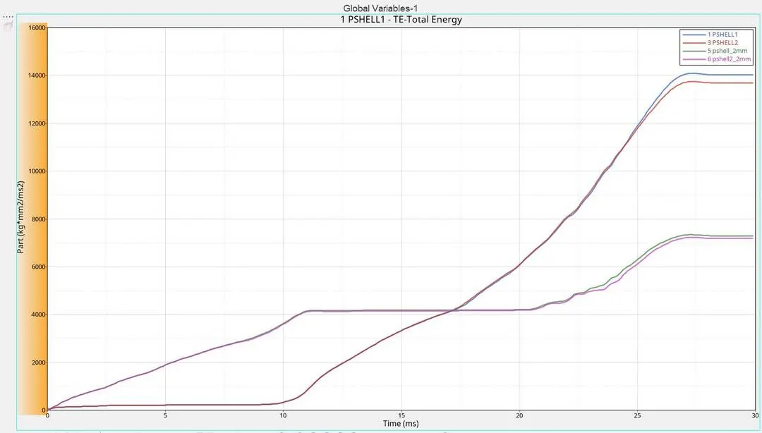
TH/PART is ploted:-
Case 6 :- Create a new notch with nodes only from opposing 2 faces and run.
* In this case we only need to make the notch at the opposite faces.
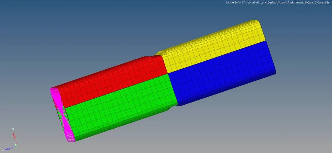
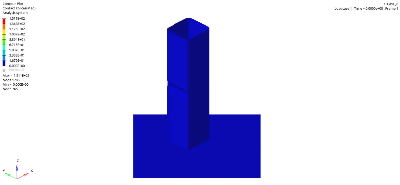
* This is case were we felt high contact force which is 1.511E+02 kN.
* Here also due to the presence of the notch the deformation is starting from the part where the notch is located.
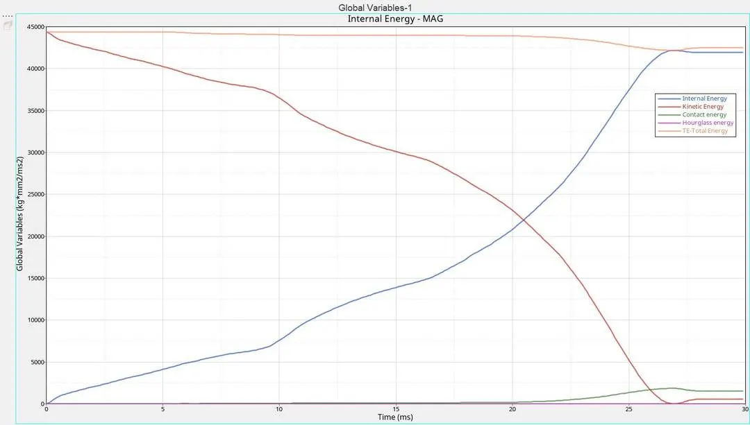
* Compared to 4 and 5th cases Contact energy is more in this case. Max contact energy here is 1851.62J.
* Internal energy is increased as the K.E is decresed due crushing against the wall and the energy is absorbed by the deformation.
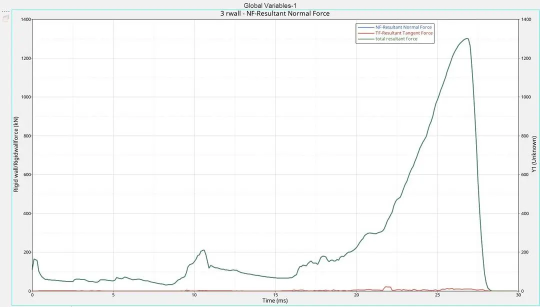
* The normal force in this case is almost same as the case 5.
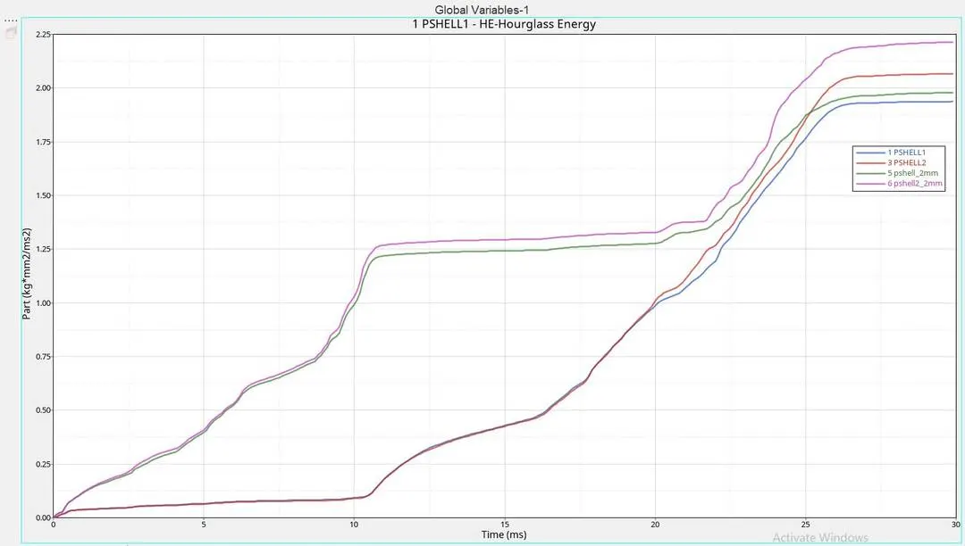
TH/PART is ploted:-
How does the notch affect the results?
* Case with Notches present:
When the notches are present it is seen that the deformation is starting from the notch region. Also the contact forces are more in the parts with notches. When notches are present the stiffness is reduced.
* Cases without Notches:
When the notch is removed the contact force and contact enegry is reduced and the stiffness is more in these parts.
Conclusion:-
Case 4 is more acceptable as the notch is not present the contact forces and energy is reduced which means the penetration happening in that case is lesser than the other cases, also the stiffness of the body is increased.