Car Floor Panel Meshing using Hypermesh
Car Floor Panel Meshing using Hypermesh
Objective :-
To perform Geometry cleanup and Meshing on Car Floor panel which is a Sheet metal Component. Also apply thickness , assign property and check the normals.
Procedure :-
STEP 1 :- Component Study
1. The component is the floor panel of the car trunk, where we keep the spare tire.
2. Its a sheet metal component. So Uniform thickness.
3. This component is having a uniform thickness of about .75 through out.
4. The model is having so many converging areas and small sharp areas. Due to that we will be having a greater tria percentage .
STEP 2:- Geometry Cleanup.
1. After importing we can see that there are many empty components and also some components are spread out in different components.
2. We can organise them.
3. First Move the whole components to a single component using Tools> Organise> Collectors.
4. Select Surfaces and choose Surfaces that we want to move.
5. In destination component choose the component to where we want to move these Surfaces.
6. Click on move.
7. After that we can delete the unwanted components by going into Delete (F2) option

8. In the option choose Components> Preview Empty.
9. In the bottom left corner we can see how many components are empty.
10. Click on delete to delete those empty components.
11. In this model we are not having so many deformations.
12. We only have some unnecessary surface and some missing surfaces.
13. To find out these errors easily put the view in Topo mode
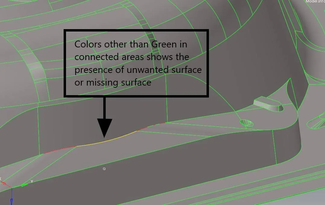
14. To find out the deformation in these areas correctly we can use Mask option
15. Select the Mask tool in side of the window or click on F5
16. Select the visible surface and mask them. Then we can see some surface inside the outer surface which are unnecessary.
17. Delete these surface and Toggle the edge again by Geometry> Quick edit> Toggle to make the correct.
18. Also in some regions we can see that there are some small missing regions.
19 To fill them we can use Geometry> Quick Edit> Filler Surface. and select the edge of the surface to be filled.
20. If it is not working we can use the Ruled option. Geometry> Surface> Ruled.
21. Then select the two lines which are to be conneted to form a surface. Click on create.
STEP 3:- Mid surface generation and its geometry cleanup of mid surface.
A. Auto mid-surface (Just for referance while making manual Mid-surface)
1. There is Auto Midsurface option but we cannot use that in here because it will delete some features that we needed. But we can first create one to know about the shape which our manual mid surface will be almost be looking like.
2.For Auto midsurface go to Geometry>Midsurface
3. Go to extraction options then choose skin offset for better offset
4. Then go back to auto extraction, Select the parent surface body which we want to create auto mid surface. Duplicate it. Then click on extract.
5. After sometime we get the auto midsurface
B. Manual mid surfaceing
1. This component is a Sheet metal component so it will be having Uniform thickness.
2. We can check the thickness of some part seperately to make sure that the thickness is uniform.
3. Checking thickness at the edges will be easy but checking thickness at area exept the sides is difficult so we can to one thing.
4 Create temp nodes (Shift+F2) on both sides of a place of the parent surfaces.
5. Then use distantce (f4), Two nodes option to measure, Thus we can measure the thickness of inside areas.
6. After getting thickness we can start manual mid surfaceing. For manual mid surfaceing we will use the Offset in Surace edit option.
7. Geometry>Surface Edit> Offset.

8.In offset option choose continuous offset
9.Then select the surface to be offseted
10.Make duplicate of that surface. Then click on offset.
11. While doing the manual mid-surface we can do the whole part in a single stretch because the thickness is same.
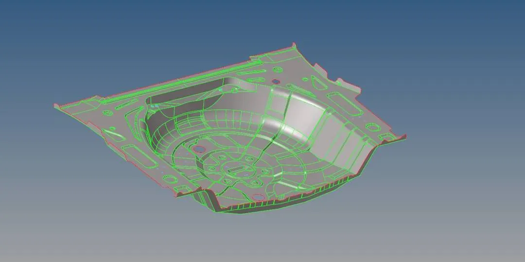
Mid surfaceing the bubble shaped feature.
1. The whole part can be offseted easily, but you can see that the the bubble shapped features have some irregularities so we can make one features mid surface good and position it to other places.
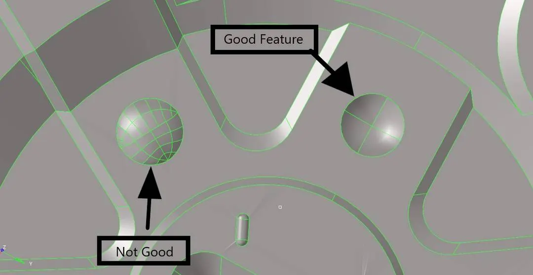
2. Delete the irregular features.
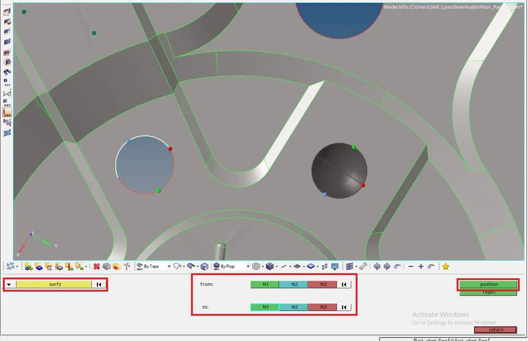
3. Make sure that the feature that we are gonna offset is good and free from deformations.
4.Now go to Tools> Position.
5. Select the surface. Right Click Duplicate.
6. In from Select the nodes of the surface that we are going to position.
7. In to Select the nodes in which direction we want it to be positioned.
8. If u want the original on to be positioned in another area in same direction place the node as the original one in to option.
9. Or if you want to get the surface in opposite direction reverse the direction of N1 and N2
10. Click on position.
11. If dont get the surface exact as you expected. Use the translate option and translate the surface to match in the exact position.
12. Use toggle option to bring the connectivity with surfaces.
Cleaning up of the mid surface
1. Small gaps and unnecessary hole can be filled using Filler surface tool in quick edit
2. Small deformations can be made good using Replace points in quick edit
3. Lines which will be failing for minimum length error can be eliminated using toggle edge in quick edit.
4. Proper connection shall be established between lines.
STEP 4:- Setting up Quality criteria
1. For setting up the criterias as given the project we need to go to Criteria editor.
2. For that go to Preferences> Criteria file settings
3. In that tick in the boxes near which all the criteria we wanted and give the values for each criteria.
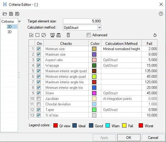
4. Save the Criteria file so that we dont need to enter it each time.
5. Click on Apply
6. Click on Ok.
STEP 5:- Meshing
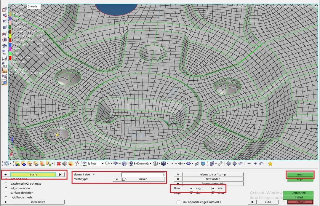
1. After setting up the Quality criteria we can start the meshing process.
2. 2D> Automesh.
3.After clicking on the surface box Select the surfaces needed to be meshed.
4.Give element size as 5 as in the question
5. Give the mesh type as Mixed.
6. Elements to surface component is choosen to add the mesh to the surface component
7. Keep connectivity is given to keep the mesh connectivity
8. Check the Align and size to get a good mesh flow.
9. Click on mesh.
10. We can change the surface to elements and select the elements we want to remesh and click on Mesh to remesh the elements
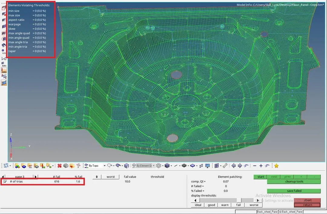
11. The mesh we get will have a huge number of trias, fixed trias and rotational quads. also the mesh flow wont be in a good pattern.
12. Inorder to make it a good mesh. We will reduce the number of trias ( removing the unwanted trias)
13. This can be achived be going to 2D> Quality Index> Cleanup tools.
14. We can remove trias and get good mesh flow by using the cleanup tools
- Main points to remember in Tria management:-
- No trias in corner or edges.
- No opposite trias.
- No back to back trias.
- No trias at hemmings or fillets or keep it miimal as lower as possible
- No rotational quads.
- No trias should share a boundary with feature line.
- Connectivity between elements
- Split and perform the mesh.
- Use mixed type mesh for irregular surfaces and quad type only for rectangular and square surfaces.
- The main tools used while eleminating trias are in 2D>quality index>cleanup tools
- Place node :- Used to manually move a node
- Smooth :- used to smooth the elements to get better mesh flow
- swap edge:- to swap the sides of the element
- Node optimize:- place the node in an optimize position which try to reduce the errors
- Element optimize:- optimize the element sides to eliminate errors.
- Split/Collapse edges:- used to split the elements.
- Drag tria elements :- to move the trias in the mesh.
- Split quad elements:- to split quad elements
- combine tria elements :- used to combine tria elements
Other than this there are:-
smooth> Shift+f12:- used to smooth the mesh to get a good mesh flow
project> Shift + f7:- to align the lines with features
Translate> Shift+f4:- to move nodes to eliminate errors.
15. Also in some areas we can see that the surface is symmetry. In those region we can reflect the elements.
16.Tools > Reflect

17. Choose elements and Select the elements to reflect.
18. Select the N1, N2, N3 in the direction to reflect.
19. Select the base point from which the reflection is to be done.
20. Click on Reflect.
21. The reflected surface will not have any connections with the surface and lines to make connections we can project it. Using Tools> Project.
22. Connection with the lines is necessary for connectivity with the adjesent mesh and also for easy selection.
STEP 6:- Checking the Normals and Free Edges
A. To check Normals
1. To check the Normals go to Tool > Normals
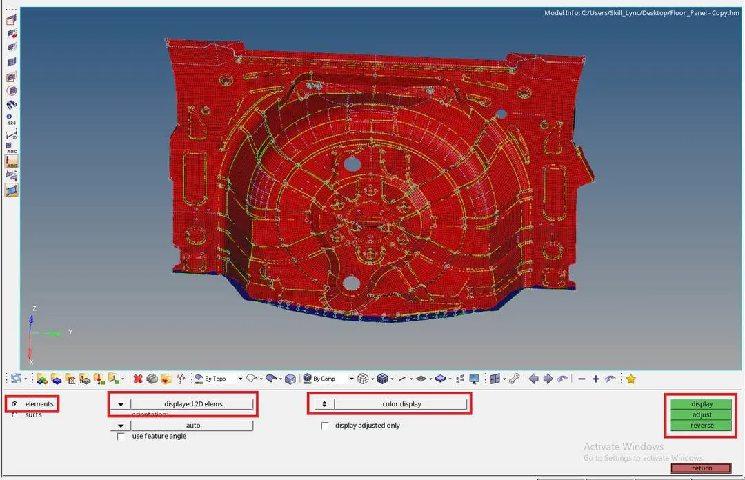
2. Choose elements
3. Select displayed 2d elements for selecting the whole elemets
4. Color display inorder for the color representation.
5. Click on Display.
6. Then we can see the whole model in Blues and reds. If the whole positive side is in one color and the negative side is in one color. Then it is ok.
7. If one side is having both colors then we need to change its normals.
8. By clicking on adjest almost all of it will be corrected.
9. But if not we need to change that by Changeing the Displayed 2D elements to Elements and select the elements which we want to change.
10. Then click on reverse. to change the normals.
B. To check Free Edges
1. For checking normal we need to go to Tool> Edges
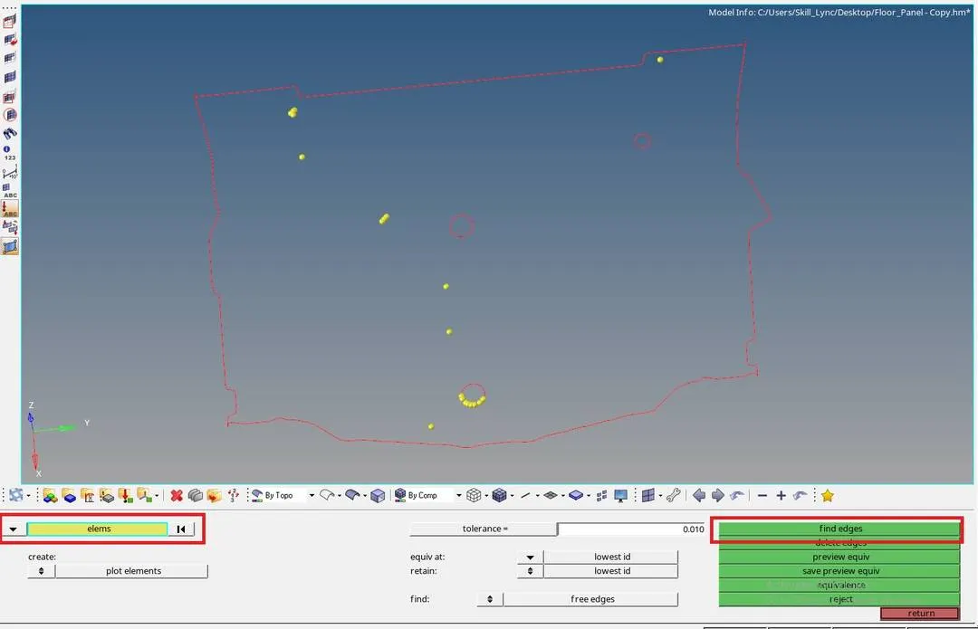
2. Choose Elements> the select the whole elements.
3.Click on Find edges.
4. Now Hide other parts and Make edges mesh only visible.
5. Now check if there is red line on any area which is not a boundary.
STEP 7:- Assigning thickness
1. After the whole meshing is done we can assigin thickness to the mesh inorder to make the 2d mesh exact as the real product.
2. This is a sheat metal model so the whole part will be having uniform thickness so we make a property and assign it to the component
11. To make property. Right click on Model view area > Create> Property.
12. Rename the property with the thickness value.
13. Also set the thickness of the property. By clicking on property we can see its details below.
14 In that we can see a T which represents the thickness give the thickness value . Click on enter.
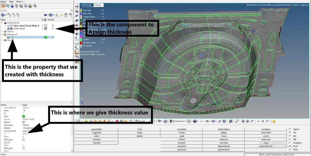
15. To Apply the property to the Components. Right click on component
16. Select assign. Choose the property of the component from the pop up dialogue box
17. Click on Apply. Click on Ok.
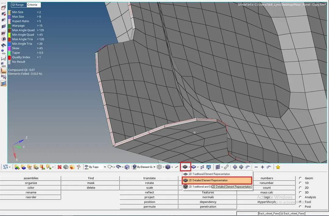
18. To see the mesh in 3D. Choose the 2D detailed element representsation.
Result:-
Finished the Mid surfacing and Meshing of the Car trunk floor panel component with no fail of quality criteria and tria percentage is 1.6. Also checked the normal and free edge and applied the thickness to the components.