Week 9 - Project 1 - Door Applique Design with Engineering Features
Heat Staking :-
In manufacturing products with thermoplastic components, it is often necessary to join a thermoplastic to a part of dissimilar material, whether it be metal, a dissimilar plastic, or other material. This technical information sheet provides design guidelines, configurations, and techniques for successful thermal (heat) staking.
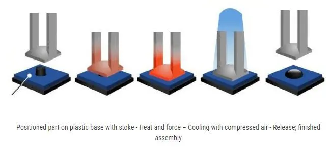
Heat Staking is a pulsed-heat process to join two or more parts out of which one at least is made of plastic. The process is to deform the plastic material using heat and force at a set process time. The bond is made by partially de-forming the plastic part in order to fix the other.
Heat Staking makes it easy to bond metal to plastic and is commonly used in high volume/low cost applications such as automotive, IT and consumer appliances.
The plastic is deformed by heating it to a temperature above the glass transition temperature. Super-heated air or a thermode is used for this. Pressure is then applied to create the stake. After the stake has been formed, the plastic should be cooled down again below the glass transition temperature. Cooling is performed under constant pressure to ensure good fixation of the parts. Compressed air can be applied for cooling when a thermode is used.
Heat is used to facilitate the creation of the stake. Heat control is critical, especially for glass-filled plastics which often have a process window of less than 10 degrees Celsius. When the temperature is too high, the glass fibers come out of the plastic which leads to a rough surface and adhesion to the thermode. If the temperature is too low, the plastic will crack due to cold deformation.
Heat Staking Benefits:-
1) Similar and dissimilar materials may be joined: metal to metal, plastic to plastic, metal to plastic
2) Accurate control operating within a small process window
3) Local heating resulting in no damage to surrounding materials
4) Processing of glass-filled materials
5) No mechanical vibration
6) Many heat-stake shapes possible through custom designed tools
Locators :-
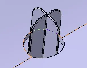
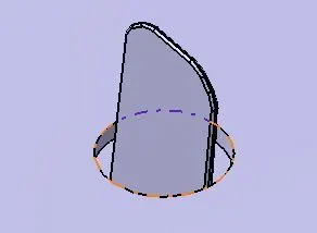
Locators are used in parts to arrest motion between parts. There are two classifications of Locators, 2-way and 4-way. A simple method to remember the difference between them is to consider the 3 axes of translational motion, and the 6 corresponding directions or Degrees of Freedom. A 2-way locating pin restricts motion along 1 axis (or 2 degrees of Freedom), like a round pin in a slot. Likewise, a 4-way pin restricts 4 degrees of freedom along 2 axes. A round locating pin located concentrically in a hole is a common application of a 4-way pin, and helps to further secure the piece. In order to sufficiently locate a part, a minimum of one of each type of pin is required to prevent excess motion of the workpiece, and more locating components may be used as needed.
PROCEDURE:
The procedure is divided into two parts first creating the tooling axis then performing the draft analysis.
Creating tooling axis :-
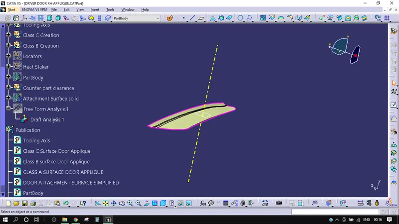
1) The first thing to do is finding out the possible tooling direction by visually checking the part. Rotate the part in all directions and find out the most suitable direction for tooling. Here in case of this part viewing from Y direction, we can clear the face in tooling.
2) Then we create a point on the surface of the part, we can create the point anywhere on the surface but usually, we take CG point or take a point near to the center. On this point, we put a new axis system.
3) Then we are finding out the tooling axis in Y direction.
Steps to do draft analysis:
1) Use Generative shape Design, Open Feature draft analysis option from Insert > Analysis > Feature draft analysis.
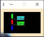
2) A new window pops up by default it will be in quick analysis mode. Change the range to 3deg.
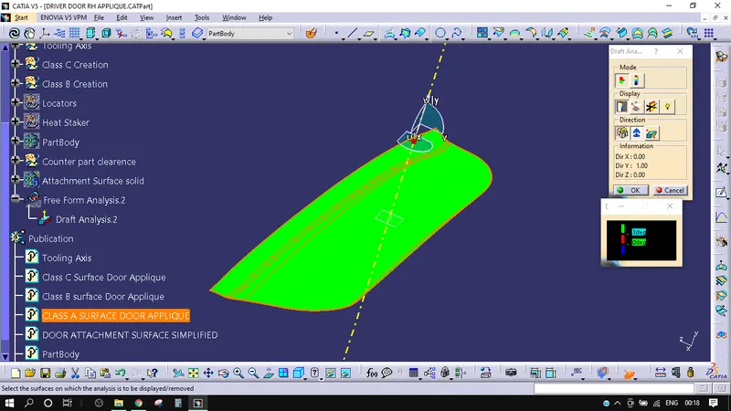
3) Next you have to position the compass on the tooling axis by dragging the compass from the top right corner of the working area. The W axis of the compass should be inline with the axis.
4) Then you have to define the compass by click on the compass icon on the draft analysis window. Then lock the position of the compass by clicking the lock icon.
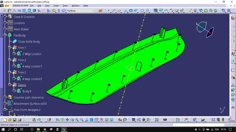
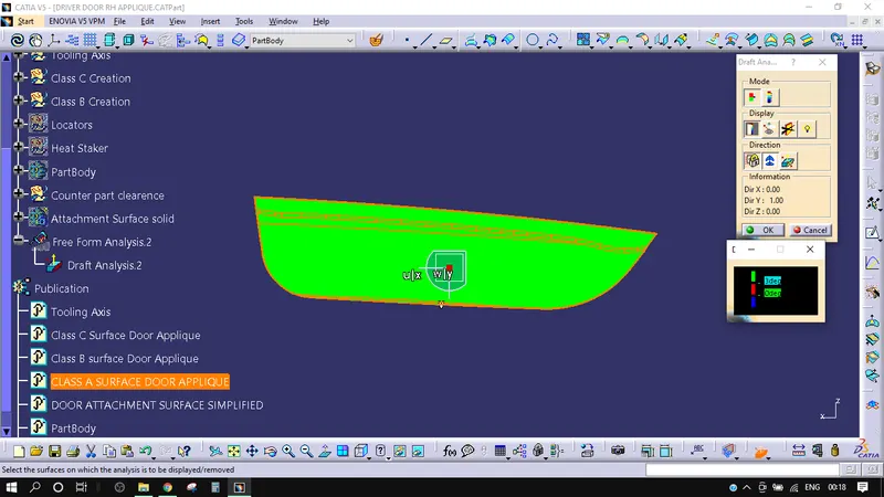
5) After that select the surface and the whole surface will show a color range. Here the A surface is fully in green color, which means all faces are having a minimum draft angle and it’s good for manufacturing. If any face is showing blue or red color we have to work on that face to give a good draft.
Creation Of Class B Surface :-
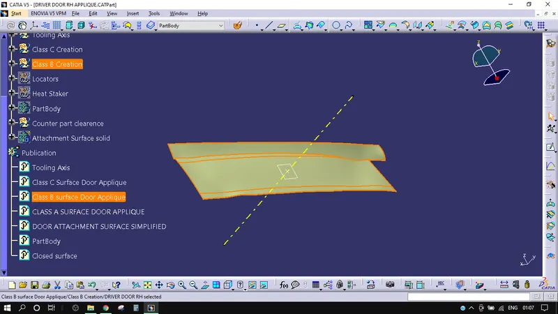
B Surface is the inner side of the component, where A surface is the outer and visible side.
1) For the creation of the B surface we will Extract the flat surface in the A surface using Extract tool.
2) Untrim the extracted flat surfaces.
3) Then Extrapolate the extracted parts.
4) Trim the surfaces and remain only the wanted surfaces and offset it with the thickness of 2.5mm
5) Add fillets as in the A surface.
Creation Of Class C Surface :-
C surface is the thickness side of a part which joins the A surface and B surface.
1) First create the boundary line of the A surface.
2) Then using the Sweep command make the side surface with draft.
3) In Sweep using the Line option. For Subtype select "With Draft Direction"
4) For Guide Curve1 Show the Boundary of A surface.
5) Draft direction show the tooling axis.
6) For Angle give 3 degree and Length of 5mm.
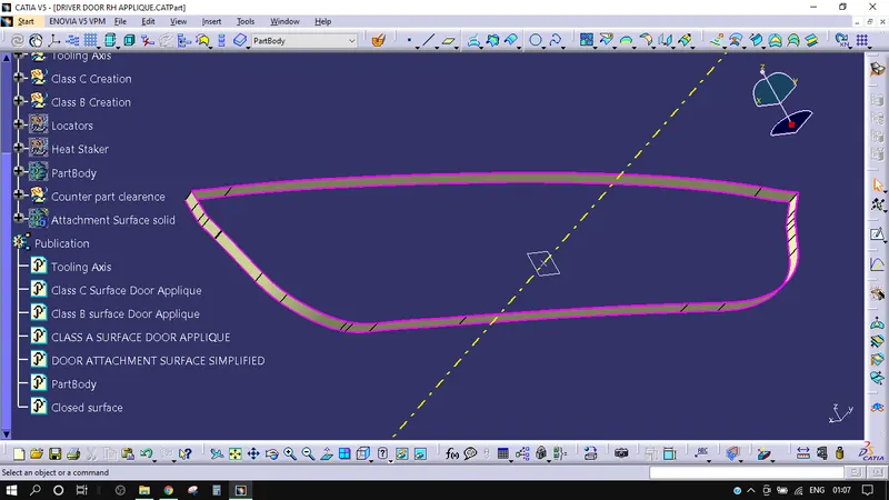
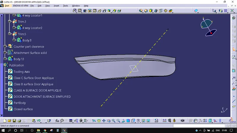
7) Then use trim option to trim the unnecessary surface. And join A,B and C surface to form a Closed surface.
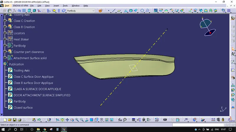
8) Go to Part Workbench and make a solid part with the closed surface.
Creation of Heat Stake :-
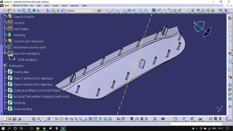
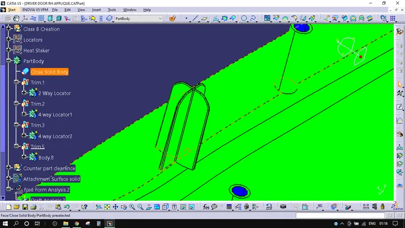
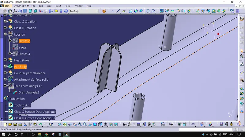
1) Create a sketch and Draw the sketch of the Heat stake
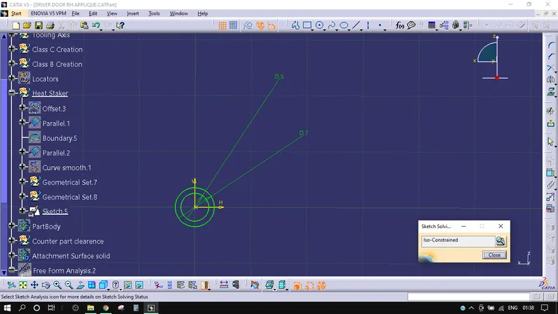
2) Pad the Created sketch
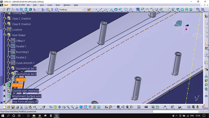
3) Give Draft to it
4) Copy paste as much as we required
5) Union trim it with the main body
Creation of Locators :-
1) Create a sketch and Draw the sketch of the Locator
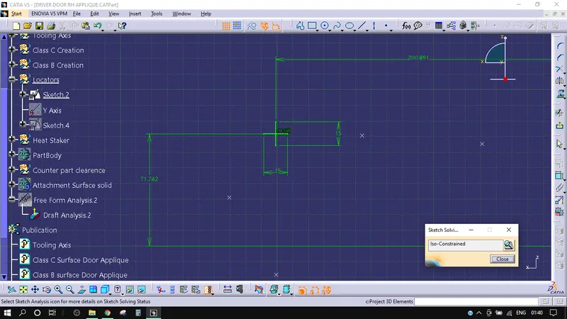
2) Pad the Created sketch
3) Give Draft and edge fillet to it
4) Copy paste as much as we required
5) Union trim it with the main body
Creation of Counter part Holes :-
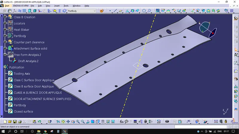
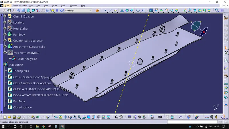
1) Create a circle sketch for making holes on the other part to make the heat stakes and locators to pass through.
2) Pad the circles
3) Remove these pad cylinder from the other Attachment part
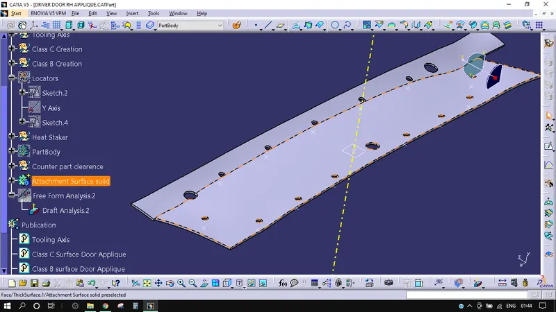
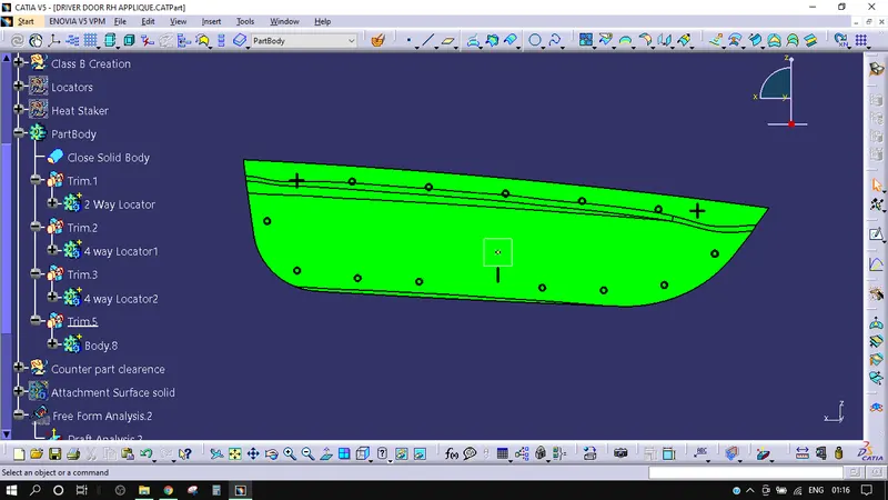
Screenshots of the solid model with the proper color code of the draft angle in various orientations (Isometric, Front, Side, and Top View)