Assignment 2
Answers :-
1. To calculate the speed of sound in steel rail we need young's modules(E) and density (Rho)
E= 210000
Rho= 0.0078
Speed of sound = c= √(E/Rho)
=√(210000/0.0078)
=5188.745m/s
2. Length of the rail = 1000mm
The time takes for a shock wave to travel from one end of the rail to the other= Te= (l/c)
= (1000/5188.745)
= 0.19272ms
3. Time for sound to travel length of rail = 0.19272ms
4, 5 and 6.
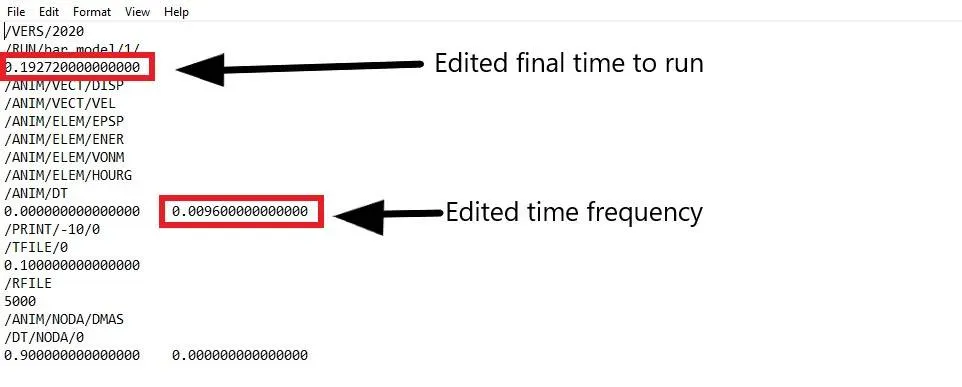
We can edit this itself in the rad file or we can give values in the hypermesh Engine cards
1.Open the rad file using Import solver deck
2. In file type choose Radioss (Block)
3. In file choose the file to be opened , click on import.
4. In model browser , click on Card
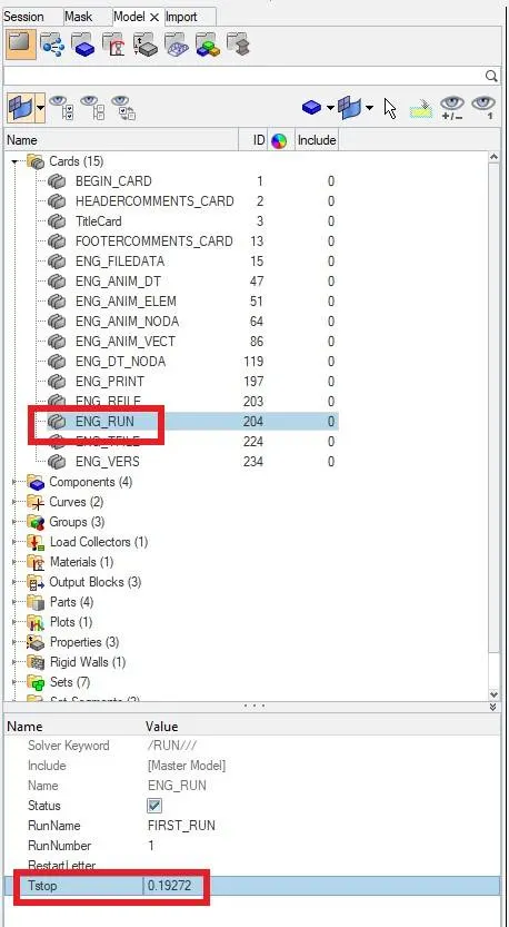
5. From that choose ENG_RUN
6. In the entity editor for Tstop give final time of run which is 0.19272
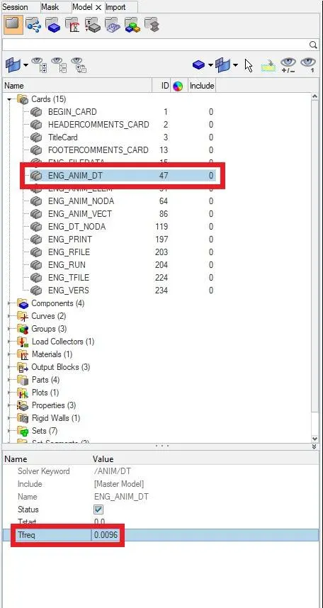
7. Now from cards choose ENG_ANIM_DT
8. In entity editor for Tfreq give value for getting 20 animations.
Tfeq =( Te/ No. of animations)
=(0.19272/20)
=0.0096
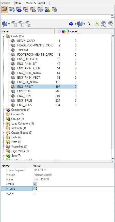
9. Now from cards choose ENG_PRINT
10. In entity editor for N_print give value -10
11. To make it run go to Analysis> Radioss
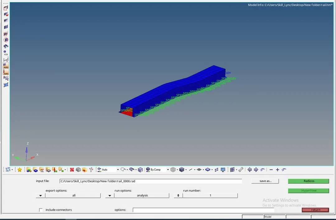
12. Save the input file.
13. Click on radioss.
14. Then the Solver will do the analysis and show it in Hyper works solver view.
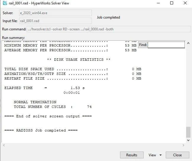
15. to see the result in animation click on Result in solver view.
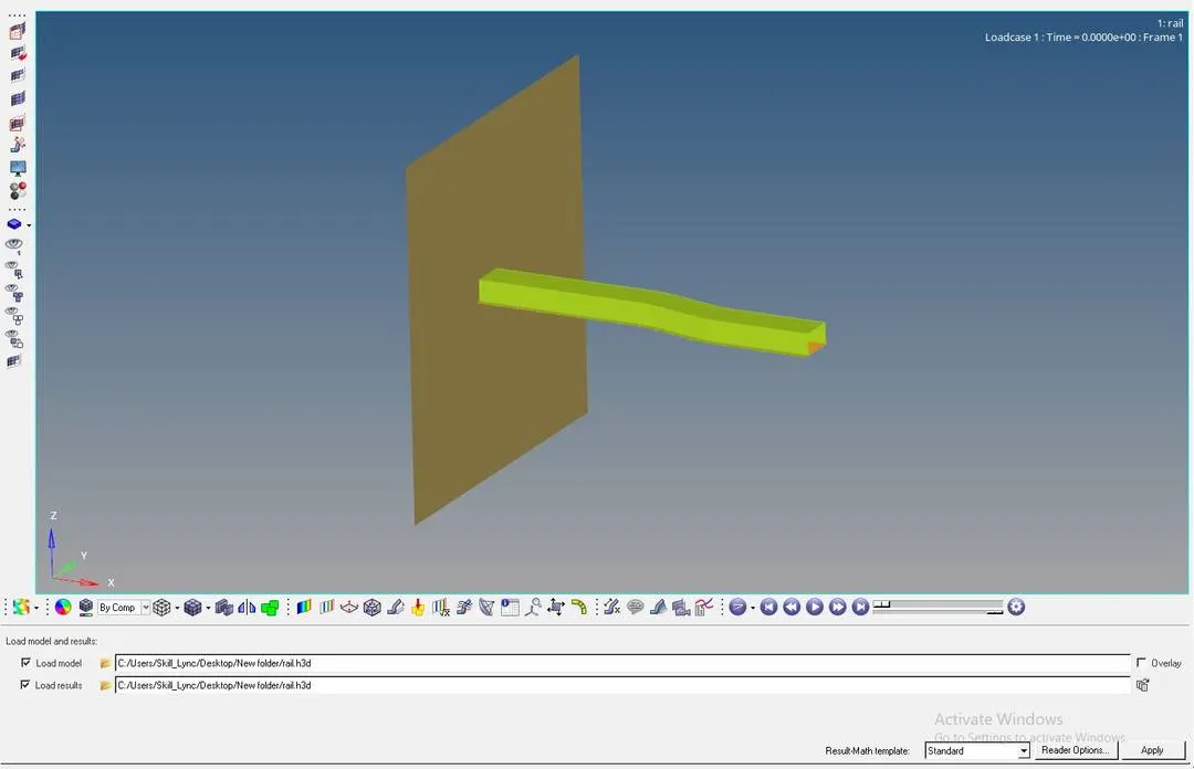
16. Click on apply in the above opened window.
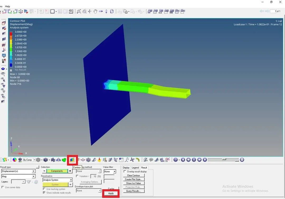
17.Click on Contour and click on apply.
18 Then select the play button see the animation Based on the contour.
7. Tetra meshing and Hexa Meshing
Objective:- Do Tetra and hexa mesh on the Given models
Procedure:-
A. Tetra Meshing the Housing Component.
Step 1:- Importing Cad Geometry
1. Import the cad model.
2. File > Open> Model> select the file open
3. or if it is in step or igs file, Use File > Import > geometry.
Step 2:- Geometry Cleanup
1. The cad model should be studied and geometry cleanup should be done
2. Check for the fillets and small teeth like structures, defeature them because they will also make tet collapse errors.
Step 3:- Meshing
1. go to 2D> Automesh, Select the whole surface, Change the element type to Trias .

2. In element size as 5
3. Click on Mesh
4. After the 2D mesh is ok, now we can do the 3D meshing
5. For 3D meshing go to 3D>Tetramesh.
6. Choose elements under Fixed trias/quads for tetra mesh.
7. Select the whole 2D meshed elements.
8. Click on Mesh.

9. Also after meshing everytime check the mesh by masking some parts to make sure that the tetra mesh is done.
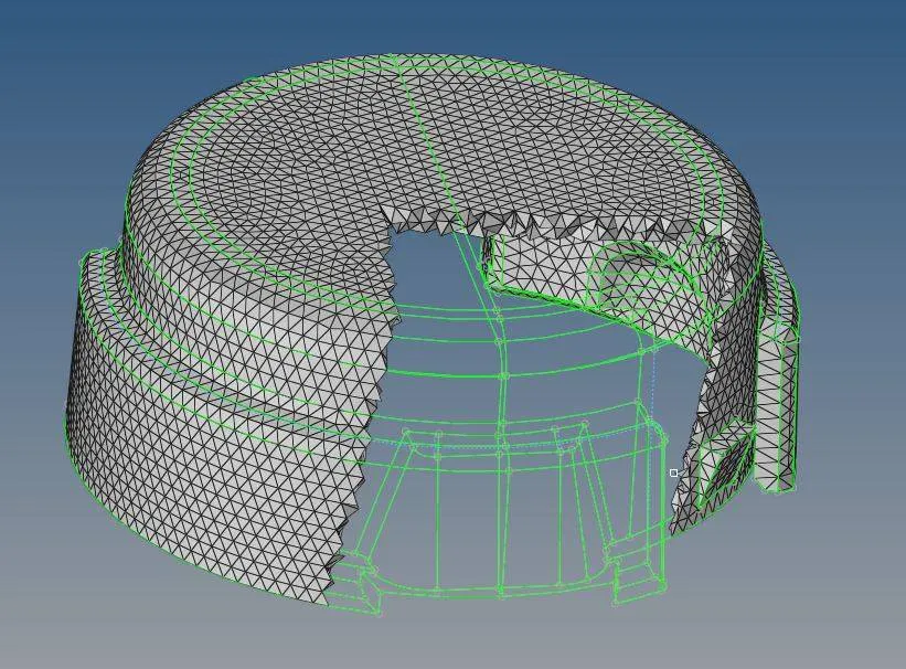
10. For Volume mesh go to, 3D> Tetra mesh> Volume tetra mesh.

11. Choose Surfaces under Enclosed volume.
12. Select the surfaces which we want to mesh.
13. Give elements size.
14. 2D element type as trias
15. 3D elememt type as tetras.
16. Wisely check the boxes of Use Curvature, Use Proximity. Because always choseing the both will make some deformations or sometimes make a 2D mesh instead of 3D
17. Also for auto cleanup, check the Cleanup elements option.
18. Click on mesh.
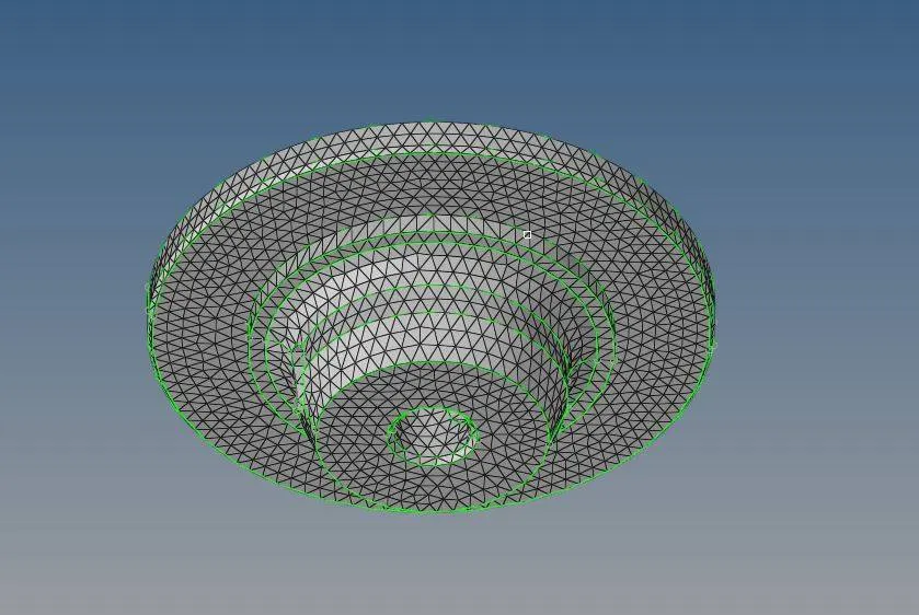
19. Check Tet collapse by pressing F10. and give value for Tet collapse as .15 Then click on tet collapse.
20. Then you can see the number of elements failing for tet collapse in the bottom left corner

B. Hexa Meshing Arm Bracket.
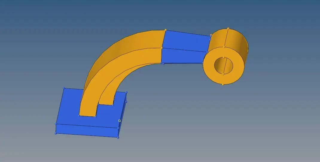
Step 1:- Importing Cad Geometry
1. Import the cad model.
2. File > Open> Model> select the file open
3. or if it is in step or igs file, Use File > Import > geometry.
Step 2:- Geometry Cleanup
1. The cad model should be studied and geometry cleanup should be done
2. Check for the fillets and small teeth like structures, defeature them because they will also make tet collapse errors.
Step 3 :- Meshing
1. We can mesh this model part by part so we start it with the base
2. We mesh the bottom part first. Take the base and make a 2D mesh on its surface By 2D> Automesh
3. Select the surface to be meshed.
4.Give Target element Size as 10
5 . Click on mesh
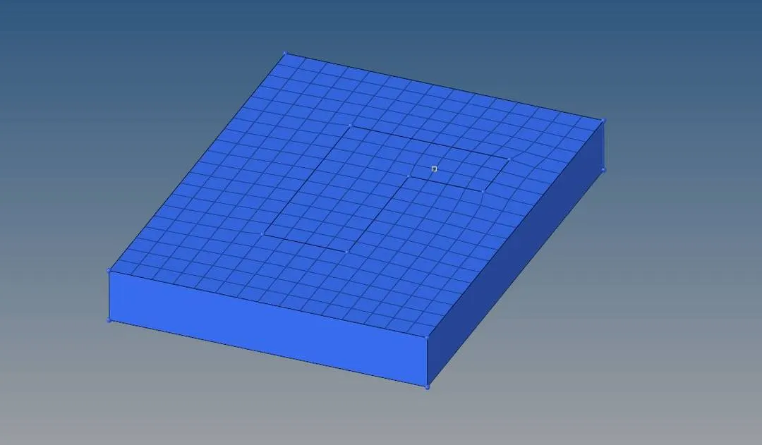
6. After making the 2D mesh we can Make the hexa mesh of the base by Element Offset.
7.3D> Element Offset
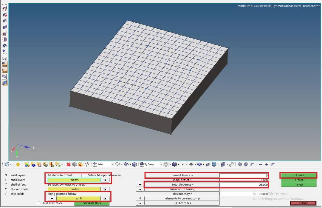
8. In 2D elems to offset Select the elements which you want to offset.
9. In Along geometry to follow Select the sides of the base through which the hexa mesh should be generated.
10. Give the number of layers that we want in Number of Layers.
11. Give the thickness in Total thickness.
12. Click on offset+
13. Now we make the arm curve part by useing 3D> Spin option

14. Choose spin elements
15. In 2D elements select the elemnets to spin
16. Give tha axis or directions and the base point.
17. Give the angle at to which we want to spin our elements.
18. Number of sets we want shall be given in On spin
19. Click on spin + or - as our requirement.
20. For making the straight part of the arm we can use 3D> Linear solid

21. Make 2D mesh at both ends of the straight arm.
22. In From select the elements at one end and other end in To
23. For select the nodes on both ends 2D mesh in the same direction.
24. Give Density the number of layers we need in the arm.
25. Click on solids.
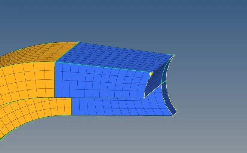
26. For the boss part we should 2D mesh on side
27. Then we can use the 3D>Solid Map.
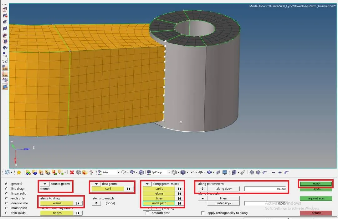
28. In Source geometry select none
29. In Elements to drag select the 2D elements
30. In the dest geometry select the destination geometry
31. In Along geometry Select mixed> Then Click on node path and show node path.
32. Give Element Target size in Along size.
33. Click on mesh
34. After meshing the whole part. Delet the whole 2D elements In the mesh.
35. Click on Delete> Elements > right click on Elements choose by Config> choose Quad4
36. Click on Select entity> Delete Entity.
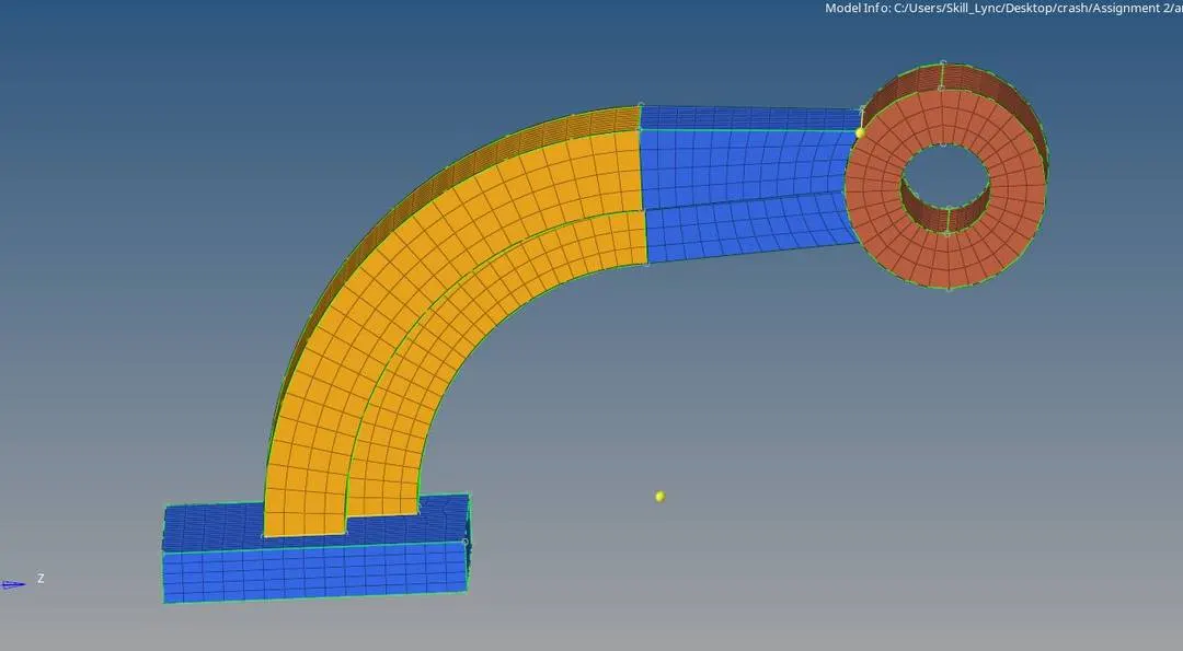
Result:-
1. All the Calculations are done and the answers are written above.
2.3D Hexa and tetra meshing is done on the given models