Week 9 - Project - Master Section Development
AIM:-
To Create the Closed part body of B PILLAR from given Class-A and develop attachment features.
OBJECTIVE:-
The objective of this challenge is to develop Closed Surface Model using Master Sections and develop attachment features for fixation of parts by following OEM Design standards and procedures in CATIA SURFACE and PART WORKBENCH.
PROCEDURE :-
Tooling Axis Creation and Draft analysis :-
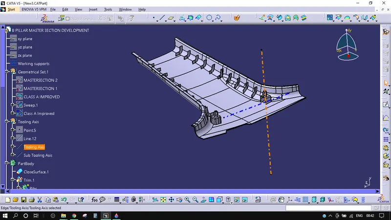
Class A surface of a component refers to the aesthetic surface which is visible to the naked eye when we observe a body(such as a car). In general, they are high-quality surfaces which have some fine finishing and aesthetic look to it. As plastic components are injection moulded, we need a tooling axis for the core and the cavity. The tooling axis/direction is the direction in which the moulds(core and cavity) move apart/together which means it serves as the reference to design your data up against. One more point to be noted here is that the draft is always provided along the tooling axis so that it can easy when the component/mould are part. We have been provided with the class A surface and in that surface, we create a tooling axis. Now that the tooling axis is obtained, we perform a draft analysis on the given class A surface.
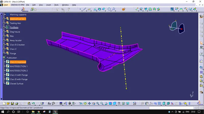
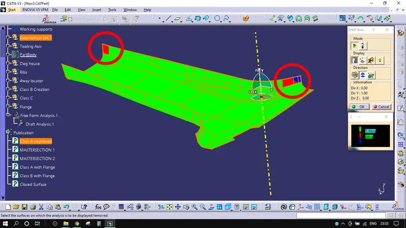
1) From the Draft analysis we can see that at 2 portions the Draft angle is Failing for the tooling axis.
2) Even if we try to change the Tooling Axis this cant be fixed.
3) As this is an Class A Surface we need to report it to higher designing authority other than trying to fix it because its is Class A we cannot change it as our wish.
As this is an exercise Im ignoring this error and proceeding.
Class B & C Creation with Master Section :-
For the creation of the Class B and C we dont have any dimensions but we have 2 Master Sections from which we can extract the dimensions we needed.
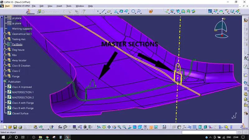
With the thickness value we get from the master section we created the Class B and C surface.
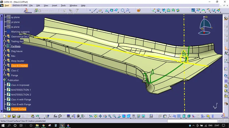
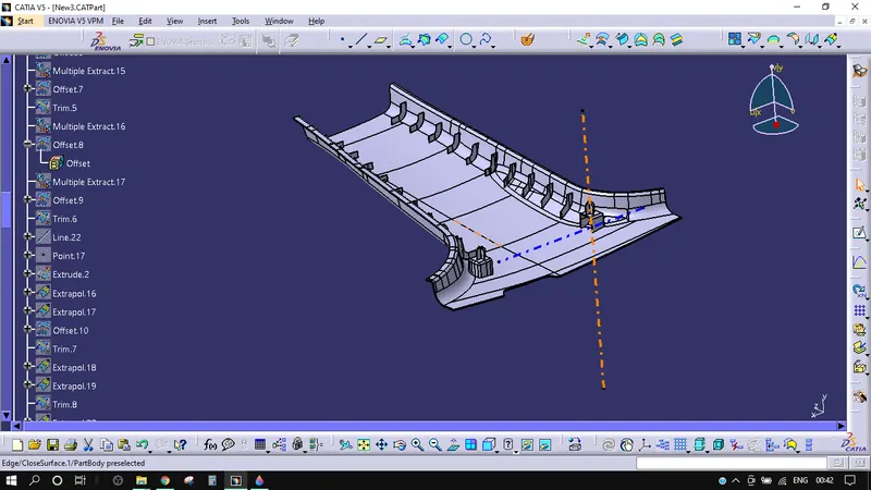
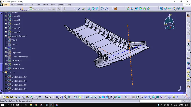
Then I used Closed Surface tool to create a solid body from the Closed surface.
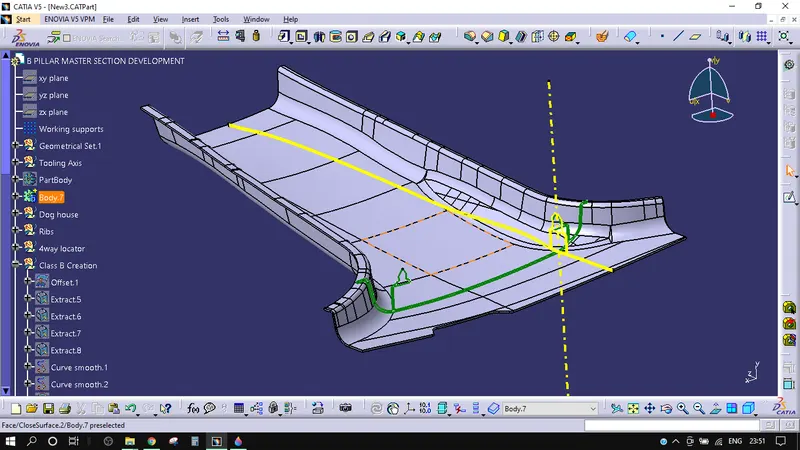
Creation of Dog House and Ribs :-
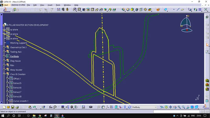
Below given is the master section for Dog house and 4 Way Locator. But we can see that yellow master section is OK but green is wrong, This should also be reported to higher authority . For now im following the yellow master section with the industrial standerds to make ribs, 4 way locator and Dog house to complete the exercise.
Dog House Design
Dog House Width (X) :-
-Minimum width is 12mm
-3:1 ratio of steel width to height
-2:1 is preffered
Dog House Draft :-
-Minimum Draft (D) for doghouse is 1.5 degree
-If a slide is being considered, this requirement can change to 3 degree minimum
Dog House Height (H) :-
-Minimum Height of Dog house is 6mm less than 6mm causes weak steel condition.
- 3:1 ratio of steel width to height , 2:1 is preffered.
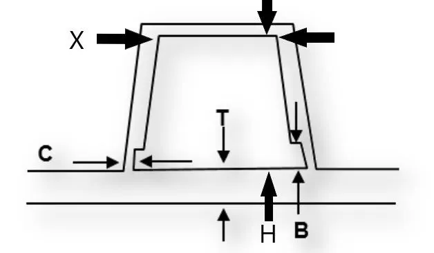
-"C" is where the doghouse contacts the backside of the surface
-Doghouse wall thickness at the intersection of the part wall ( C ) should be 40% or less than the main wall stock ( T ).
-Height of ( B ) should be between 3.0 – 6.0 mm
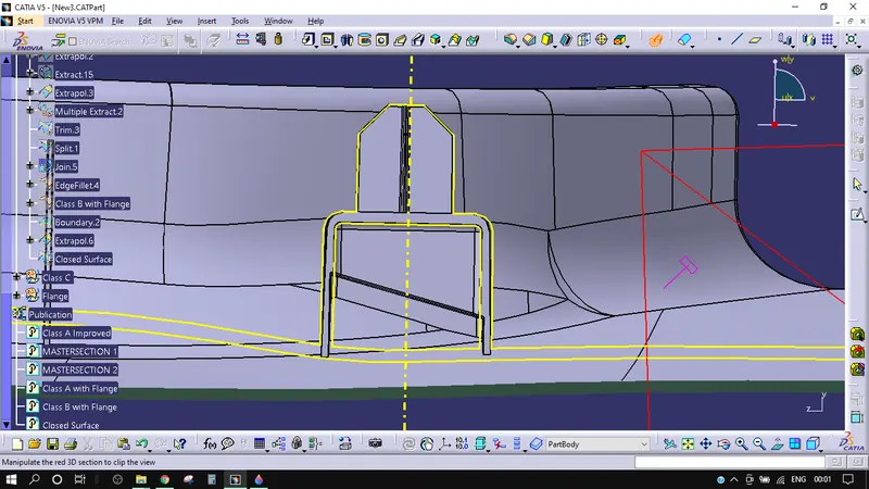
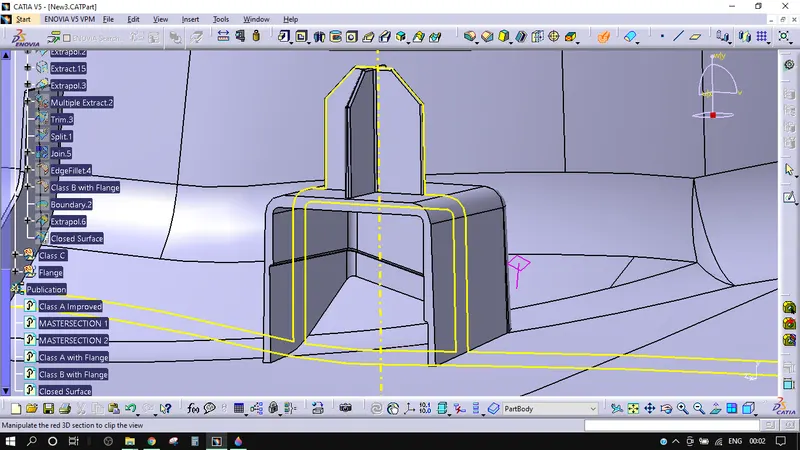
RIB DESIGN
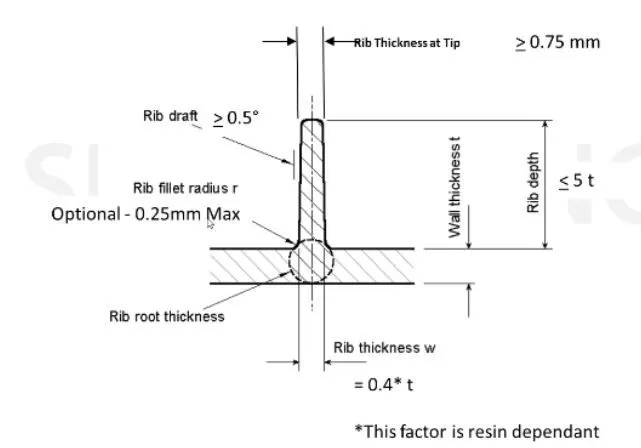
Draft :-
-0.5 degrees per side minimum.
-Allows the ribs to release from the mould
Rib Thickness (w) :- [ w=0.4*t ]
-Measure base thickness of the rib at tangent of radius if radii are modeled in
-The larger the area at the base of the rib, the more retained heat.
-The retained heat causes more shrinkage, which causes sink.
-Minimum thickness, which will be at the top or tip of rib = .75mm
Rib Fillet (r) :-
-Optional Rib Fillet radius = 0.25mm max
-Do not want to significantly increase rib thickness
-Must not violate 40% thickness requirement
Rib Depth / Height :-
-Rib height < 5* nominal wall thickness.
-Limited by draft & thickness requirement.
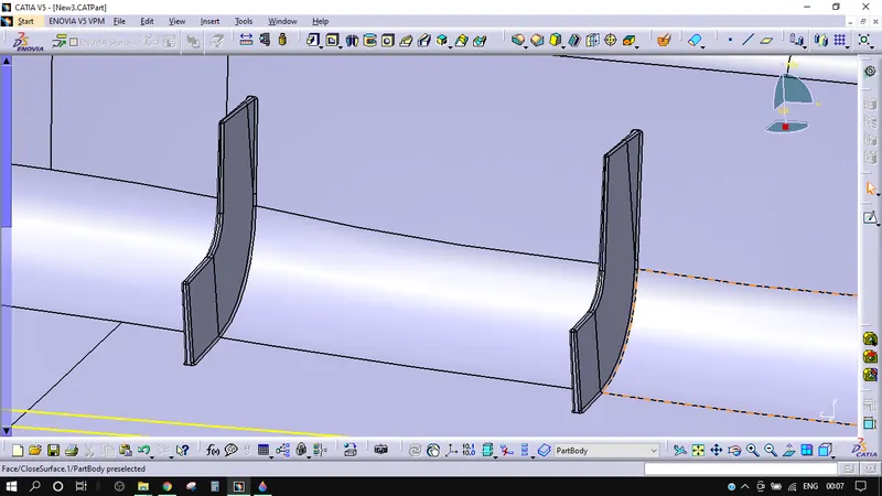
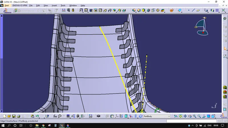
Draft analysis of the Solid Body :-
1) For the Main body and Ribs we use one main tooling axis.
2) For the Dog House we use another side Tooling axis.
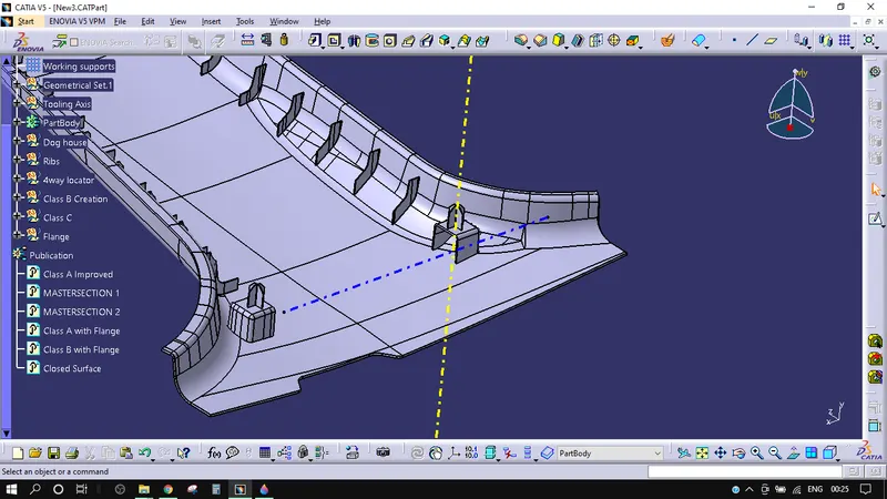
For the Main body we use Draft angle of 3degree :-
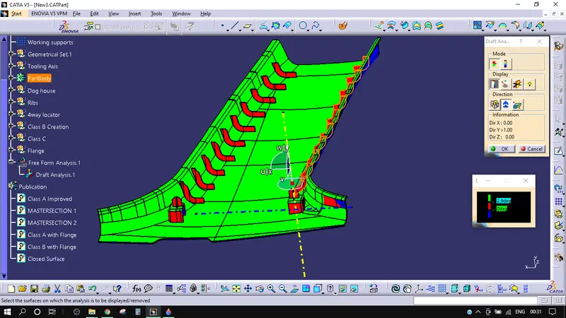
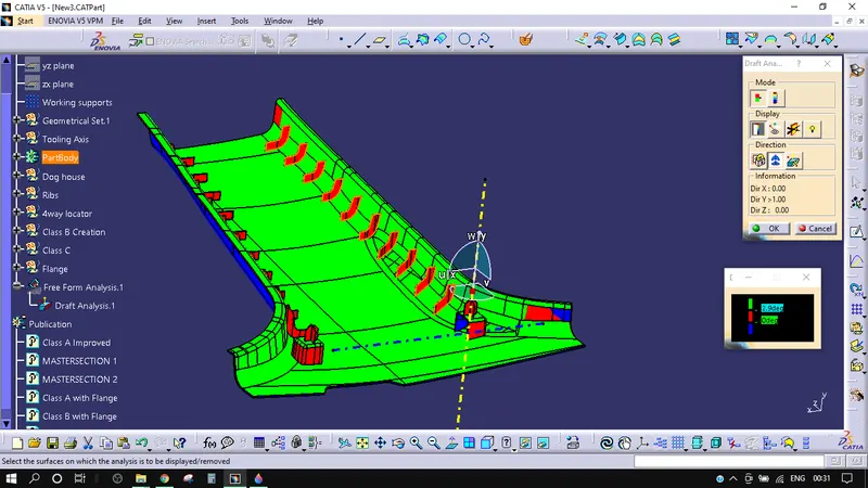
2 Portions were Causing us problem in the beganing in Class A those portions still fails for draft analysis others show green which is OK.
For Ribs and 4 Way Locators we use a Draft angle of 0.5 degree:-
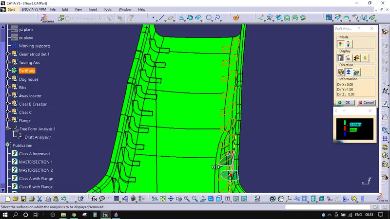
All ribs pass the draft analysis and shows Green color.
For Dog houses we use a Draft angle of 1.5 degree for outer part and 0.5 degree for under cut :-
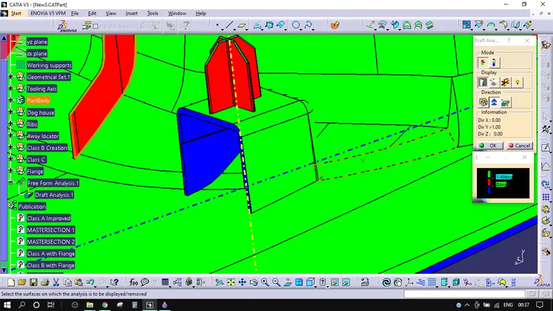
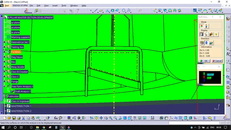
TREE STRUCTURE :-