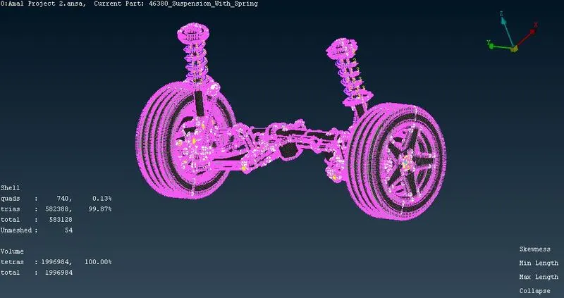
Project - 2 - Meshing on the suspension Assembly
Meshing an Automotive Suspension Assembly
AIM :-
1) Check for the geometrical errors.
2) Mesh with the given element Quality criteria.
3) After meshing the component the thickness has to be assigned for mid surfaces.
4) Use tetra elements to model non-uniform thickness components.
5) Give appropriate connections to connect the component.
THEORY :-
Modern suspensions are composed of hundreds of different parts, and vehicles vary tremendously in their suspension designs, but every suspension is composed of certain basic parts which are common in all, some of which are shown below.
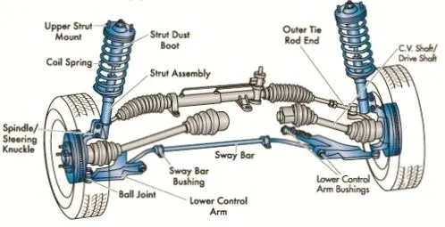
The basic components of a suspension system are as follows:
CONTROL ARM (a movable lever that fastens the steering knuckle to the vehicle frame or body)
CONTROL ARM BUSHING (a sleeve, which allows the control arm to move up and down on the frame)
STRUT ROD (prevents the control arm from swinging to the front or rear of the vehicle)
BALL JOINTS (a swivel joint that allows the control arm and steering knuckle to move up and down, as well as side to side)
SHOCK ABSORBER or STRUT (keeps the suspension from continuing to bounce after spring compression and extension)
STABILIZER BAR (limits body roll of the vehicle during cornering)
SPRING (supports the weight of the vehicle; permits the control arm and wheel to move up and down)
PROCEDURE :-
1) IMPORTING THE CAD MODEL:-
1. Open the ANSA software and import the cad geometry by clicking on File>Open>Browse the file from the list. Click OK.
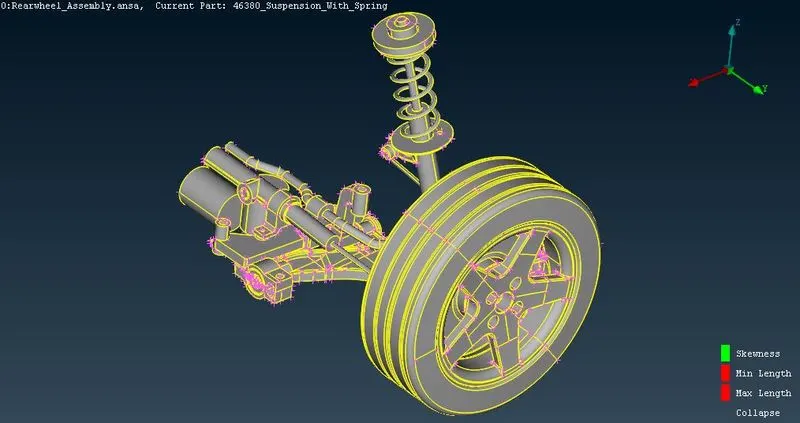
2. We can give the Length Parameter as 1 for the better visualization and to refine the model for our workability by going to Mesh Module, under Parameter tab click on Length.
Give Length as 1.
3. Perform the topo function to arrange the faces and geometry of the model by selecting the Topo Module>Faces>topo. then make a box selection over our geometry .
4. Separate the parts of rear suspension assembly by assigning them different PIDs so that it will be easy to work on them
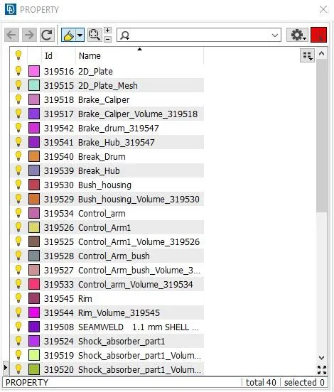
Goto Topo module > Faces > Set PID , select the parts using PID region selection tool . Upon middle click property window opens. Right click on the window > New >
PSHELL create a new PID for the part.
2)GEOMETRY CLEANUP:-
1. After doing the topo, we can do the Geometry Check, by clicking on the Checks tool on Tools toolbar.
2. From the window appearing, check in the check list as our requirement, it include options like Unchecked faces, Collapsed Cons, Triple Cons, Needle Faces etc. Click on EXECUTE.
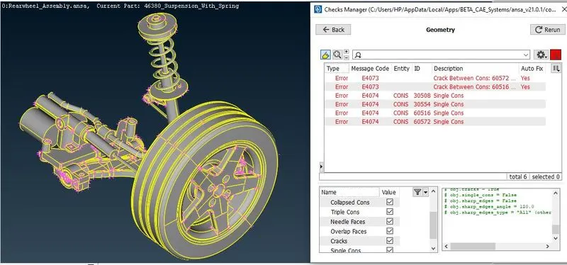
3. The errors appered can be eliminated by Auto Fix, If the auto fix can't eliminate the error we should do it manualy.
4. After clearing all the errors again do the Check.
5. If the window shows 100% with a green strip then your geometry is ready.
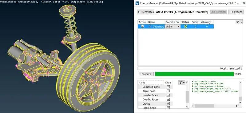
6. Uses FACES> ORIENT option to correct the orientation of the geometry.
3)MID-SURFACE GENERATION and MESHING of uniform thickness parts:-
a) Mid-Surface generation
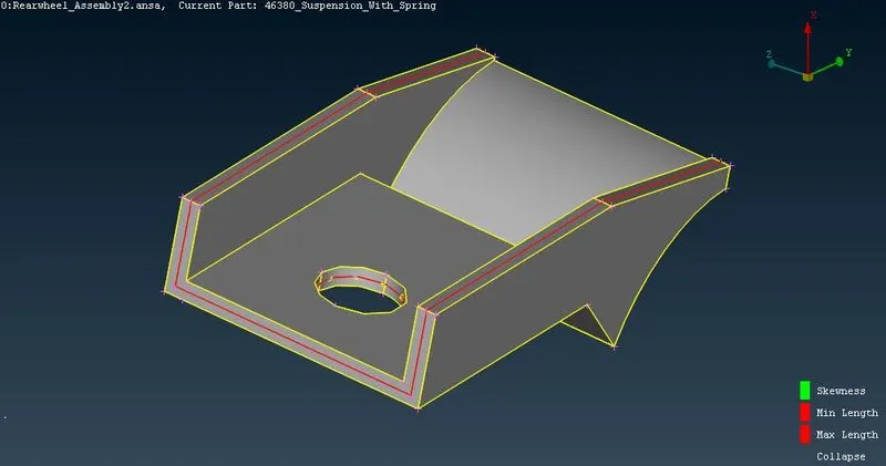
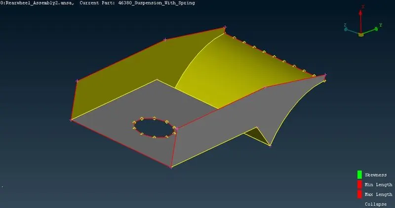
For the mid surface generation we can use Mid.surface tool or the Offset tool in the faces tab in Topo module. Click on the midsurface or offset tool, select the faces to mid surface, give the required distance, middle click the mouse button.
b) Meshing
Before starting the meashing we should set the quality criteria. For that select Utilities tab and select Quality Criteria or F11. Set the criteria as our requirements.
Our Required Quality Criteria:-
|
S.No |
Quality Criteria |
Value |
|
1 |
Target/Average length |
4 |
|
2 |
Minimum Length |
2 |
|
3 |
Maximum Length |
6 |
|
4 |
Aspect |
3 |
|
5 |
Warpage |
15 |
|
6 |
Skewness |
45 |
|
7 |
Jacobian |
0.7 |
|
8 |
Minimum Quad Angle |
45 |
|
9 |
Maximum Quad Angle |
135 |
|
10 |
Minimum Tria Angle |
30 |
|
11 |
Maximum Tria Angle |
120 |
Before starting the meshing process we need to select the delete in Hotpoints in Topo module. to delete the unwanted hotpoints and go to mesh module , select Length under perimeter tab in Mesh Module and give the target length.
For meshing a part we can use the Best option in the Mesh Generation tab. Click on Best, chose the face to mesh, middle click
After meshing for getting a good quality mesh we can use the Reconsturction or smooth in the shell Mesh tab
The quality of the mesh depends on number of rotating quads, trias and errors present. Reduce maximum number of trias , eliminate all rotating quads and errors
most of the opposite trias can be eliminated using Split and Swap in Element tab, also by using Paste option in Grid tab.
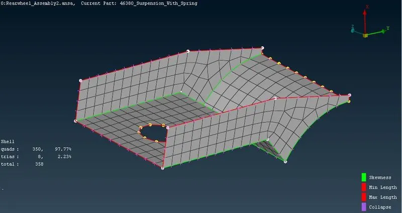
Assinging Thickness:-
We can now assign the thickness to the parts by going to FACES > Set PID then click on the part which we need to assign thickness.
Then from the coming window Right click> New > Pshell.
Double click on the property crearted, which will assign that property to the part we selected and giving the original thickness of the parent geometry in the details of the property will give the part the thickness.
4) 2D MESHING and 3D MESHING of Non Uniform Thickness Part.
Quality Criteria for Surface Meshing of Tyre and Rim (Element type: Tria) :
|
S.No |
Quality Criteria |
Value |
|
1 |
Target/Average length |
6.5 |
|
2 |
Minimum Length |
5 |
|
3 |
Maximum Length |
10 |
|
4 |
Skewness |
45 |
Quality criteria for Surface Meshing of Non Uniform thickness components other than Tyre and Rim (Element type: Tria) :
|
S.No |
Quality Criteria |
Value |
|
1 |
Target/Average length |
4 |
|
2 |
Minimum Length |
2 |
|
3 |
Maximum Length |
6 |
|
4 |
Skewness |
45 |
Quality Criteria for Volume meshing of all Non Uniform thickness components (Element type: Tetra Elements):
|
S.No |
Quality Criteria |
Value |
|
1 |
Tet-collapse |
0.2 |
Surface Meshing:-
Each part is Meshed using ortho trias or normal trias.
Ortho trias are mainly used in areas where there is complex shapes or curved areas, like fillet region.
Normal trias are used in areas where it is flat.
Meshing is done by using Spot.Mesh under mesh generaton in Mesh module also after spot mest we can use reconstruct to get a good pattern.
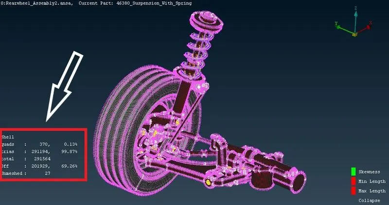
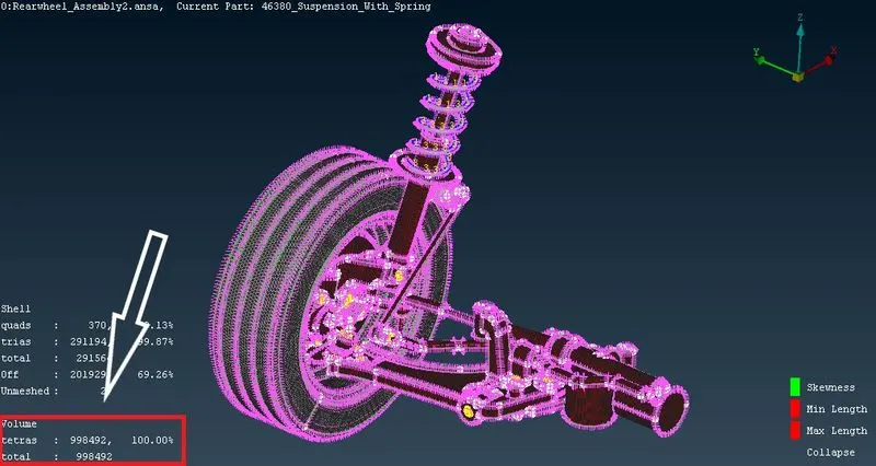
Volume Meshing:-
For volume meshing first we have to define the volume.
For that click on Define under Volume in V.Mesh module. Choose manual
Select the part. Set property ID.
Then select List in the Volume .
You can see that the part is unmeshed and undefine.
Right click on it, Select remesh.
Select Tetra Rapid or Tetra FEM.
Click ok.
Then the Volume mesh is formed for that part.
Do this for each part.
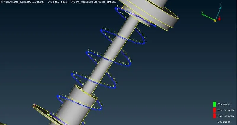
5) CREATING SPRING WITH 1D BAR ELEMENT
Generate a middle curve for the spring. By using the middle option in the curves.
Connect the curve into a single curve . By using the connect>multi option in curves.
Create a COG point for the curve to define the orientation. By Points> On COG.
Go to NASTRAN Deck.Select the CBAR element.
Change the selection type to the curve box.
Select the curve and give the middle mouse click.
select the orientation node. (The COG point)
specify the element length. In this case, The Element length is taken as 4 mm.
After Specifying the element length as 4 mm, Do middle mouse click and define a pid by creating a new PID.
Define Area by giving Radius of spring. i.e. Cross section radius of a spring.
After that, assign the cross sectional radius of the spring element.
It will calculate the cross sectional area and moment of inertia.
1D bar elements will be created.
6) CONNECTIONS
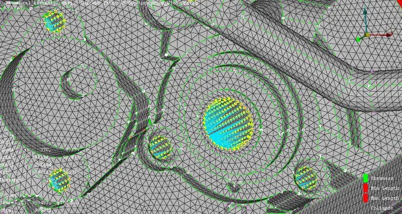
a) Cluster RBE2 Connection
Here we don't demonstrate Bolt stem modelling, we just represent the function of rigid bolt.
Whenever we identify a hole that it will be connected to any other component, we will have to deploy the Cluster RBE2 connection in which all the nodes from 2 surface will comes to join a Master node
b) Seam Weld Connection
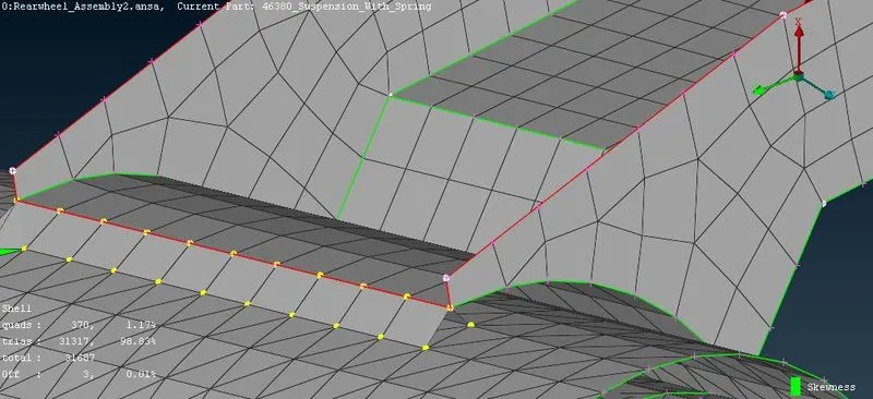
Main welds that are used in automobile industries are SPOT WELD & SEAM WELD connection. SPOT WELD are seen in cars body structural components ie, BIW structure. SEAM WELD are used in load carrying areas.
SEAM WELD that are commonly used are OVERLAP SHELL & Y-JOINT SHELL. Overlap shell is a type of FE representation which always used when the 2 parts are to be welded are PARALLEL to each other, whereas in case of Y-Joint shell are used when 2 parts are perpendicular or inclined to any angle each other.
In this model OVERLAP SHELL is used on the STRUT Assembly.
LEARNING OUTCOME:
1) Learned to surface mesh the casted elements without any quality errors formed
2) Able to recognise the parts which has to be meshed either by 2-d or 3-d mesh to be used.
3) Able to create a better surface mesh with the given quality criteria without any kinks or dents in the volume created.
4) Able to finish the model within the constrained time.
CONCLUSION:
The combined geometry made with surface meshing as well as two dimensional meshing has been meshed with the given quality criteria and proper connections have been deployed in the bolt regions inorder to make it rigidized.