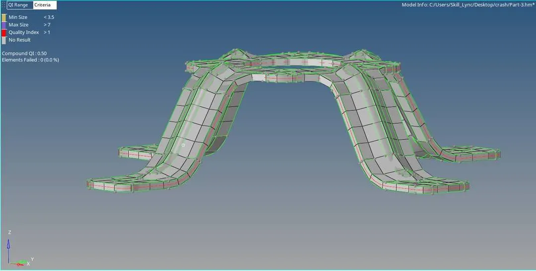
Assignment 1
Objective:-
1. Models are given carry out geometry cleanup of parent and midsurface of the models.
2.Carry out meshing of the models with the given quality criteria.
3.Assign property and give thickness to the mesh of 3 models
Procedure:-
Model No.1
Step 1:- Import the geometry and Visual Inspection
1.Import the geometry by File>Open>Model
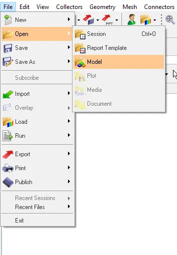
2. From the coming window choose the file we want to open.
3. Click on Open
4. Then we can see the model, Change the view to By Topo . So that we can see the topology of the model and find out the errors easily.
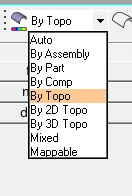
Step 2:- Geometry cleanup
1.After changeing the view to By Topo, Check the color of the edges
- RED- Free edge- Associate with only one surface
- Green-Shared edge- Associate with 2 surfaces, surfaces are equivalenced
- Yellow- T junction edge- Associated with 3 or more surfaces, surfaces are equivalenced
- Blue-Suppressed edge- Surfaces are treated as though combained into one surfaces
2. Always the parent geometry will be having green edges. If other than green is present check it and rectify the error.
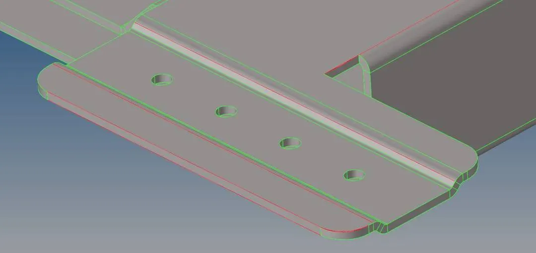
fig.1:- Red lines due to no connectivity
3. In the figure we can see that there are some red lines they are due to connectivity issues.
4. For connecting the edges we can use Geometry> Quick Edit> Togggle Edges
5. Give a tolerance value on the right side of the tool.
6. Now click on the line to toggle. If the line next to the line we click is at a distance within the tolerance value , both the lines will get joined and show green color.
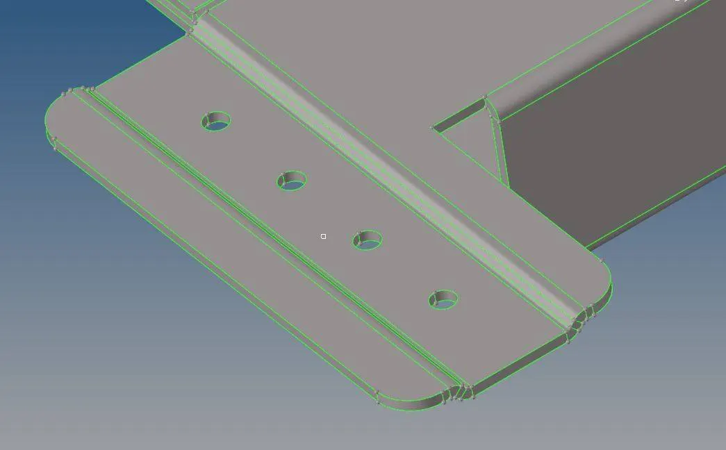
fig1.1:- After fixing connectivity issue
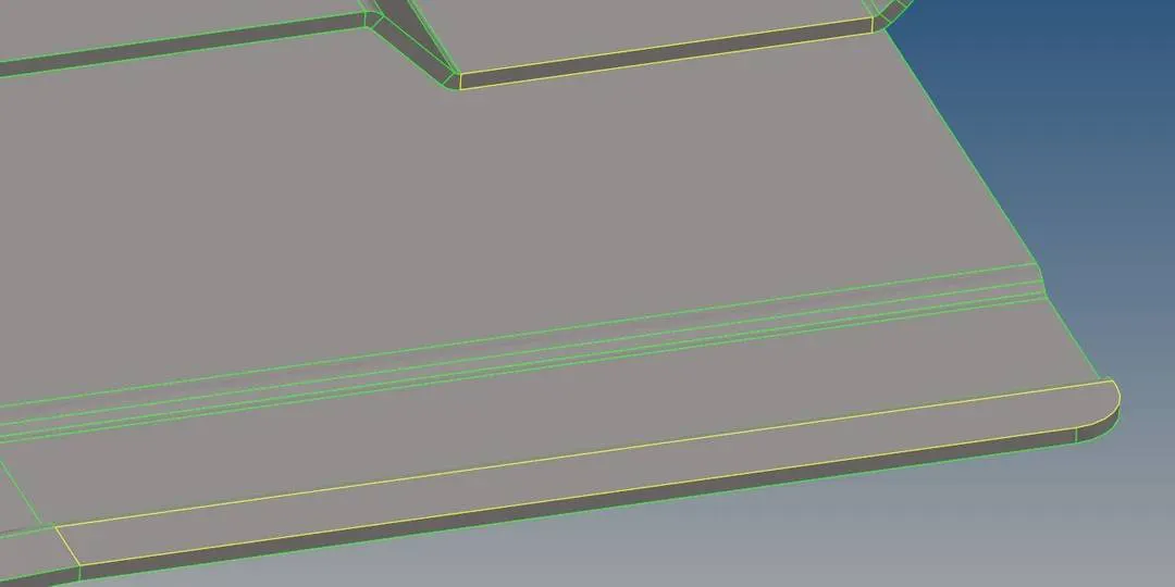
fig.2:- Presence of unnecessary surface
7. Yellow edges shows that there are connection of more than 2 edges. If the edge in original geometry is not having that much edges, there is a presence of unwanted Surface.
8. First Mask (F5) the surface and check it.
9. If its an additional surface delete it by going to Delete(F2). Choose "surf" in the drop down box.
10. Select the surface to delete. Click on Delete entity
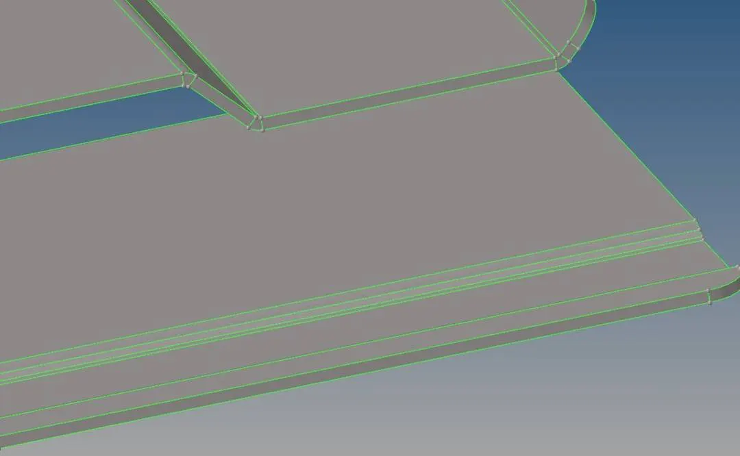
fig 2.1:- After deleting the extra surface
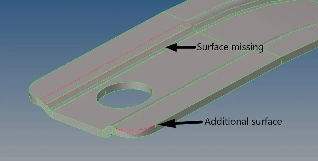
fig.3:- Missing surface and additional surface
11. The missing surface Can be filled by using Drag along lines option.
12. Geometry> Surface> Drag> Drag along line.
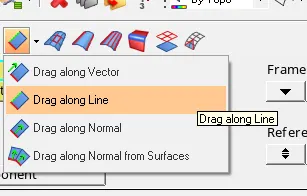
13. In that click on lines and choose the line to be draged.
14. In line list select the line along which the first line should be draged.
15. Click on Drag +
16. The additional surface should be trimed out. So we can use trim with surface or planes.
17. Geometry > Surface Edit > Trim with surface or plane.
18.there we can see 3 parts. We can use the second part.
19. In that first choose the surface to trim. then in next box select the surface with which we will tirm the first surface
20. Click on trim.
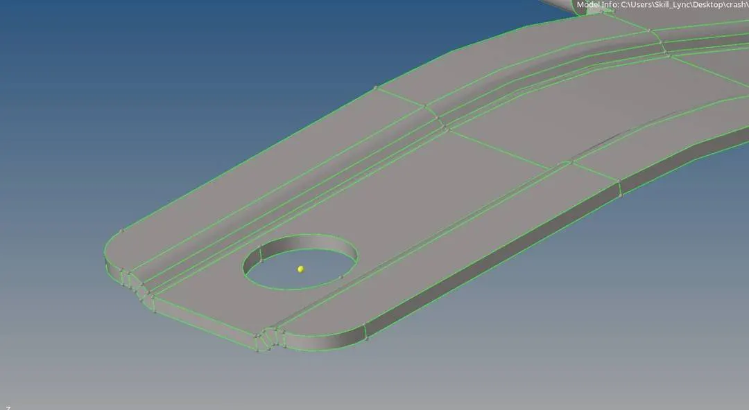
fig 3.1 :- After fixing missing and additional surfaces
Step 3 :- Midsurface generation and cleanup
1. Auto midsurface can be used in this case because there is no much complicated parts.
2. Geometry> Mid surface

3. Choose Auto midsurface.
4. Select the surface to mid surface after clicking on the surface option.
5. Click on extract.
6. after Mid surface is generated we can do cleanup.
7. As we done cleanup in parent geometry there is less errors in mid surface.
8. We can eliminated the smaller holes using Filler surface.
9. Geometry > Quick edit> Filler surface.
10. Click on the free edge of the hole.
11. Check the box near filler surface , which is suppress edge if you dnt want the cirlces lines.
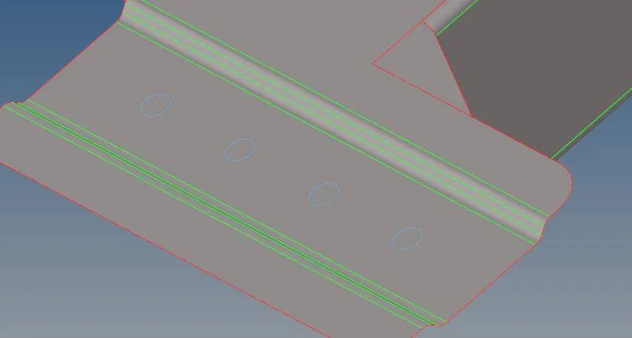
12. also toggle the lines which will be failing for minimum length errors.
Step 4:- Setting Quality Criteria and Meshing
1. Before meshing we should set up the Quality Criteria.
2. For that we should go to preferences menu>Criteria File Settings
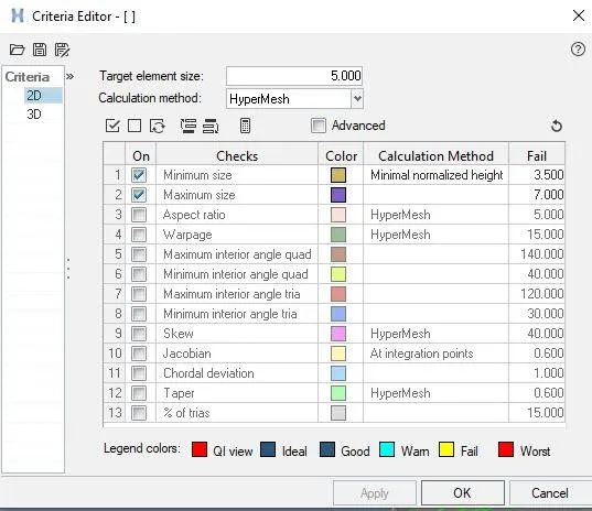
3. Then a window will appear where we can check in the box of different qualities to activate that quality.
Quality criteria for this project :- Min size-3.5, Max size-7, Target Element size-5
4. After setting up Quality Criteria we can Start meshing.
5. We can mesh using Automesh tool
6. 2D>Automesh
7. click on surface> Select Surface to mesh
8. Set Element size as 5.
9. Set Mesh Type as mixed
10. Click on Mesh
Step 5:- Assign Thickness and property
1. We are using Radioss Profile
2. To make property. Right click on Model view Browser > Create> Property.
3. We can set the thickness of the property. By clicking on property we can see its details below in property editor.
4. In that we can see a Thick which represents the thickness give the thickness value (.91mm) . Click on enter.
5. To Apply the property to the Components. Right click on component
6. Select assign. Choose the property of the component from the pop up dialogue box
7. Click on Apply. Click on Ok.
8. To see the mesh in 3D. Choose the 2D detailed element representsation.
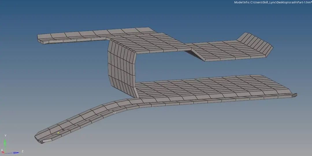
Result:-
* The geometry is cleaned from errors and created the mid surface properly.
* Meshed the mid surface without failing any of the quality criteria.
* Also given thickness by assigning property.
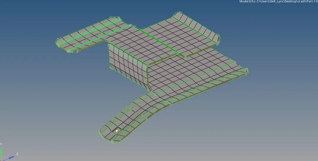
Model No. 2
Step 1:- Import the geometry and Visual Inspection
1.Import the geometry by File>Open>Model
2. From the coming window choose the file we want to open.
3. Click on Open
4. Then we can see the model, Change the view to By Topo . So that we can see the topology of the model and find out the errors easily.
5. In this model there is no errors so we can go driectly to the mid surface generation.
Step 2 :- Midsurface generation and cleanup
1. In this model using auto mid surface is not a good option. Auto mid surface is giving some errors in the model which will take some time to correct it.
2. As the component is haveing uniform thickness we can offset the outer surface to make a mid surface.
3. Geometry> Surface Edit> Offset.

4. Before starting the offset operation make a new component and rename it as Mid surface and make it current.
5.Now go to offset > select the surface > Make a duplicate of the surface in new component.
6. Give the offset value which is half the thickness.
7. Check the color normal to know the direction .
8. Cilck on offset.
9. The only cleanup needed in this model is toggle the lines which fail for min length and fill the small holes.
10. We can toggle the lines using Geometry> Quick edit> Toggle edges> Click on the lines to toggle .
11. For filling the holes we can use unsplit surface.
12. Geometry> Quick edit> Unsplit surface> click on the lines of the holes to fill it
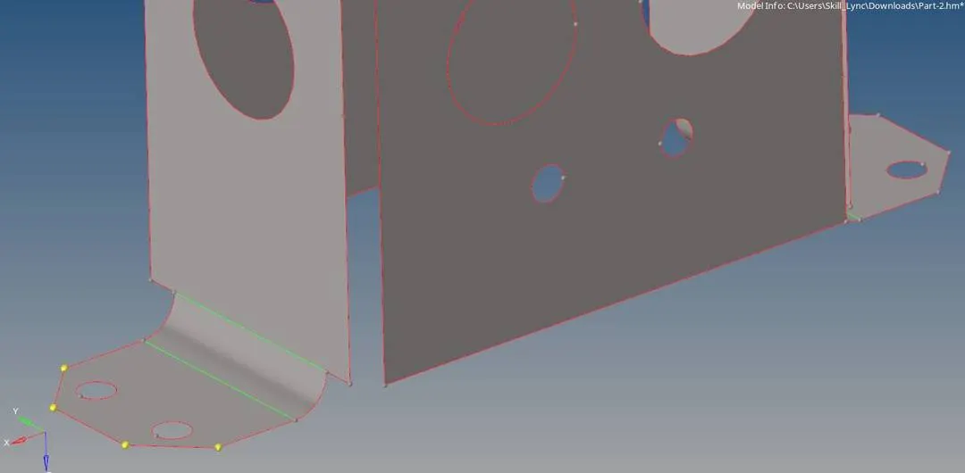
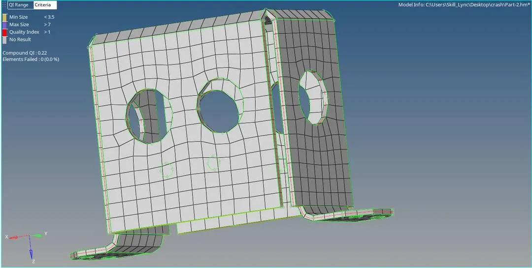
Fig Before filling the small holes
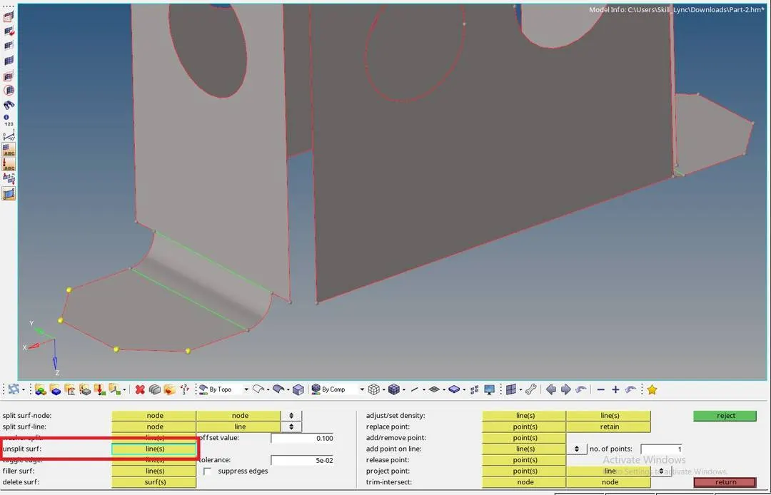
Fig after filling the small holes
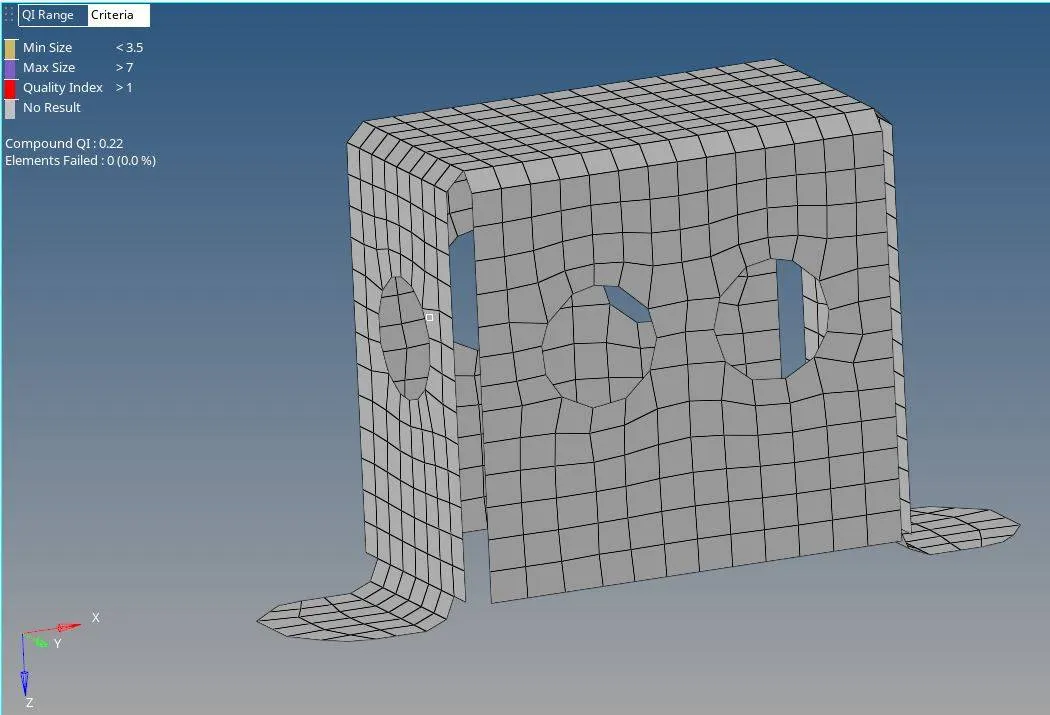
Step 3:- Setting Quality Criteria and Meshing
1. Before meshing we should set up the Quality Criteria.
2. For that we should go to preferences menu>Criteria File Settings
3. Then a window will appear where we can check in the box of different qualities to activate that quality.
Quality criteria for this project :- Min size-3.5, Max size-7, Target Element size-5
4. After setting up Quality Criteria we can Start meshing.
5. We can mesh using Automesh tool
6. 2D>Automesh
7. click on surface> Select Surface to mesh
8. Set Element size as 5.
9. Set Mesh Type as mixed
10. Click on Mesh
Step 4:- Assign Thickness and property
1. We are using Radioss Profile
2. To make property. Right click on Model view Browser > Create> Property.
3. We can set the thickness of the property. By clicking on property we can see its details below in property editor.
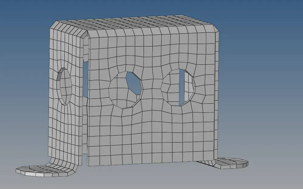
4. In that we can see a Thick which represents the thickness give the thickness value(2mm) . Click on enter.
5. To Apply the property to the Components. Right click on component
6. Select assign. Choose the property of the component from the pop up dialogue box
7. Click on Apply. Click on Ok.
8. To see the mesh in 3D. Choose the 2D detailed element representsation.
Result:-
* The geometry is cleaned from errors and created the mid surface properly.
* Meshed the mid surface without failing any of the quality criteria.
* Also given thickness by assigning property.
Model No.3:-
Model No.3:-
Step 1:- Import the geometry and Visual Inspection
1.Import the geometry by File>Open>Model
2. From the coming window choose the file we want to open.
3. Click on Open
4. Then we can see the model, Change the view to By Topo . So that we can see the topology of the model and find out the errors easily.
5. In this model there is no errors so we can go driectly to the mid surface generation.
Step 2 :- Midsurface generation and cleanup
1. Auto midsurface can be used in this case because there is no much complicated parts.
2. Geometry> Mid surface
3. Choose Auto midsurface.
4. Select the surface to mid surface after clicking on the surface option.
5. Click on extract.
6. after Mid surface is generated we can do cleanup.
7. The only cleanup needed in this model is toggle the lines which fail for min length and fill the small holes.
8. We can toggle the lines using Geometry> Quick edit> Toggle edges> Click on the lines to toggle .
9. For filling the holes we can use unsplit surface.
10. Geometry> Quick edit> Unsplit surface> click on the lines of the holes to fill it.
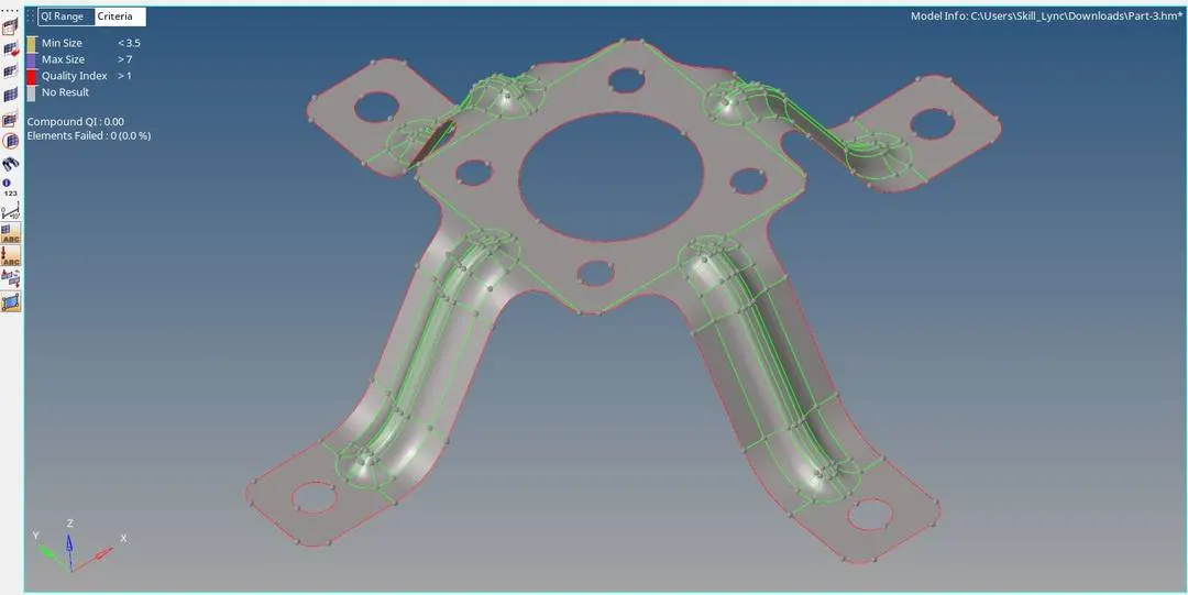
Fig before filling holes and toggleing lines
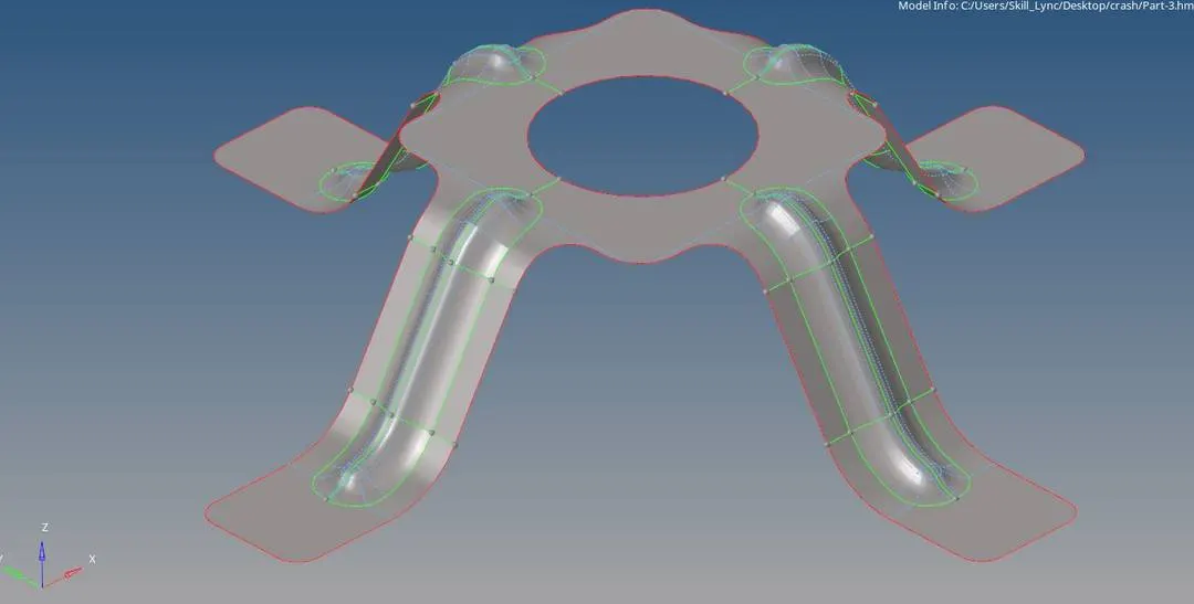
Fig after filling holes and toggleing lines
Step 3:- Setting Quality Criteria and Meshing
1. Before meshing we should set up the Quality Criteria.
2. For that we should go to preferences menu>Criteria File Settings
3. Then a window will appear where we can check in the box of different qualities to activate that quality.
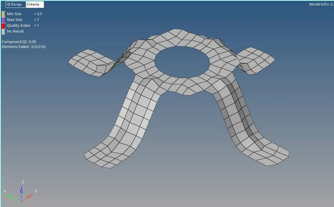
Quality criteria for this project :- Min size-3.5, Max size-7, Target Element size-5
4. After setting up Quality Criteria we can Start meshing.
5. We can mesh using Automesh tool
6. 2D>Automesh
7. click on surface> Select Surface to mesh
8. Set Element size as 5.
9. Set Mesh Type as mixed
10. Click on Mesh
Step 4:- Assign Thickness and property
1. We are using Radioss Profile
2. To make property. Right click on Model view Browser > Create> Property.
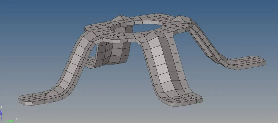
3. We can set the thickness of the property. By clicking on property we can see its details below in property editor.
4. In that we can see a Thick which represents the thickness give the thickness value(1.8mm) . Click on enter.
5. To Apply the property to the Components. Right click on component
6. Select assign. Choose the property of the component from the pop up dialogue box
7. Click on Apply. Click on Ok.
8. To see the mesh in 3D. Choose the 2D detailed element representsation.
Result:-
* The geometry is cleaned from errors and created the mid surface properly.
* Meshed the mid surface without failing any of the quality criteria.
* Also given thickness by assigning property.