Week 8 - Simulation of a backward facing step in OpenFOAM
Objective :-
1) Simulate a transient incompressible-laminar-viscous flow through the backward facing step geometry.
2) Simulate the flow without using any grading factor (i.e., GF = 1)
3) Simulate the flow with grading factor of 0.2. The cells should be finer near the walls (includig the step wall).
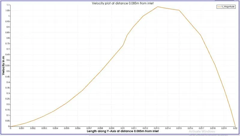
4) Measure the velocity profile at 0.085 m from the inlet of the geometry for both case studies and compare. You can use the plot over line tool for this.
5) Explain why Grading/Growth factor is essential for meshing.
Mesh specification :-
1) Number of cells along the x direction (longer dimension) = 200
2) Number of cells along the longer y direction = 20
Boundary condition specification
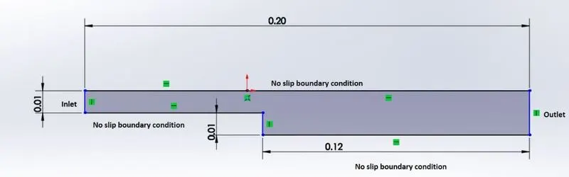
Theory :-
Here the flow is Transient incompressible laminar viscous flow, we can look into each terms
Transient flow: the velocity of a fluid particle changes with the time and the position.
Incompressible flow refers to a flow in which the density remains constant in any fluid.
Laminar flow is a flow is characterized by high momentum diffusion and low momentum convection. When a fluid is flowing through a closed channel such as a pipe or between two flat plates, either of two types of flow may occur depending on the velocity and viscosity of the fluid
Viscous flow is a type of fluid flow in which there is a continuous steady motion of the particles; the motion at a fixed point always remains constant.
Procedure :-
1. Choosing the solver
1) In the question it is said that the simulation is 'transient incompressible-laminar-viscous flow'. So we search a similar option in the tutorials.

2) Open ubuntu > press Ctrl+Alt+T to open the command terminal.
3) Type tut to open tutorial, type ls to see the folders inside tutorials.
4) Form that we will choose incompressible , because our problem is incompressible.
5) For the incompressible folder we choose icoFoam, because icoFoam is Transient solver for incompressible, laminar flow of Newtonian fluids.
6) Then we choose cavity, which is matching over problem.
7) This cavity will be in tutorial folder which is inside the Openfoam preset folder. We should not make any changes to that, if you have made any change, Openfoam wont work and we need to again install openfoam.
8) Copy the cavity folder to Run folder. Use the command cp -r cavity/ $FOAM_RUN.
9) Type cd $FOAM_RUN to open Run folder which contain our cavity folder.
10) In Run open cavity folder which we have copied.
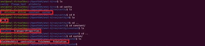
* In Cavity we can see 3 folders 0, constant and system.
* 0 contain the Initial condition (p-Pressure and U-Velocity)
* constant contain the value of constants
* system contains the file for createing mesh and applying boundary condition.
2. Geometry Creation and Mesh Setup :-
Given below is the geometry and I have divided it into three boxes .
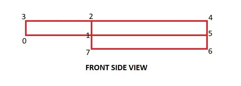
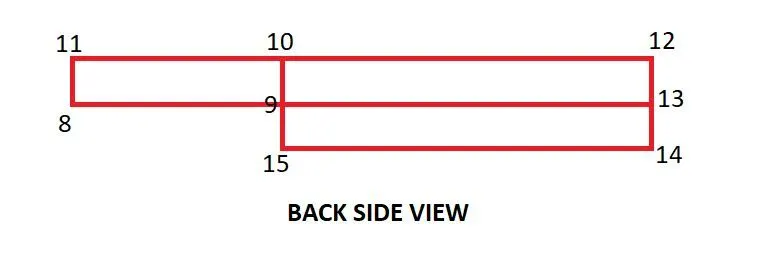
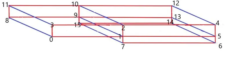
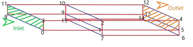
1) For creating the geometry we open blockMeshDict.
Case 1 - Simulate the flow without using any grading factor (i.e., GF = 1)
/*--------------------------------*- C++ -*----------------------------------*\
  =========                 |
  \\      /  F ield         | OpenFOAM: The Open Source CFD Toolbox
   \\    /   O peration     | Website:  https://openfoam.org
    \\  /    A nd           | Version:  8
     \\/     M anipulation  |
\*---------------------------------------------------------------------------*/
FoamFile
{
    version     2.0;
    format      ascii;
    class       dictionary;
    object      blockMeshDict;
}
// * * * * * * * * * * * * * * * * * * * * * * * * * * * * * * * * * * * * * //

convertToMeters 0.01;

vertices
(
    (0 0 0)
    (8 0 0)
    (8 1 0)
    (0 1 0)
    (20 1 0)
    (20 0 0)
    (20 -1 0)
    (8 -1 0)
    (0 0 .1)
    (8 0 .1)
    (8 1 .1)
    (0 1 .1)
    (20 1 .1)
    (20 0 .1)
    (20 -1 .1)
    (8 -1 .1)                                   //-----------> Here we give the co-ordinate of the vertices of our geometry
);

blocks
(
    hex (0 1 2 3 8 9 10 11) (80 10 1) simpleGrading (1 1 1)
    hex (1 5 4 2 9 13 12 10) (120 10 1) simpleGrading (1 1 1)
    hex (7 6 5 1 15 14 13 9) (120 10 1) simpleGrading (1 1 1)
);                                            //---------> Hex will create the face and the simplegrading will create the Mesh. Simplemesh is to apply the grading factor. It is to specify where to make the mesh courser and finer

edges
(
);

boundary                                     //-------> This is to assign the boundary condition
(
    inlet                                    //------> This is the inlet face
    {
        type wall;
        faces
        (
            (8 0 3 11)
        );
    }
    outlet                                  //------> This is the outlet face
    {
        type wall;
        faces
        (
            (12 4 5 13)
            (13 5 6 14)
        );
    }
    fixedWalls                              //------> Here we give the faces which should be fixed wall
    {
        type wall;
        faces
        (
            (11 3 2 10)
            (10 2 12 4)
            (8 0 1 9)
            (9 15 7 1)
            (14 15 7 6)
        );
    }
    frontAndBack                           //------> This represent the front and back planes
    {
        type empty;
        faces
        (
            (0 1 2 3)
            (1 5 4 2)
            (7 6 5 1)
            (8 9 10 11)
            (9 13 12 10)
            (15 14 13 9)
        );

    }
);

mergePatchPairs
(
);

// ************************************************************************* //
Case 2 - Simulate the flow with grading factor of 0.2. The cells should be finer near the walls (includig the step wall).
/*--------------------------------*- C++ -*----------------------------------*\
  =========                 |
  \\      /  F ield         | OpenFOAM: The Open Source CFD Toolbox
   \\    /   O peration     | Website:  https://openfoam.org
    \\  /    A nd           | Version:  8
     \\/     M anipulation  |
\*---------------------------------------------------------------------------*/
FoamFile
{
    version     2.0;
    format      ascii;
    class       dictionary;
    object      blockMeshDict;
}
// * * * * * * * * * * * * * * * * * * * * * * * * * * * * * * * * * * * * * //

convertToMeters 0.01;

vertices
(
    (0 0 0)
    (8 0 0)
    (8 1 0)
    (0 1 0)
    (20 1 0)
    (20 0 0)
    (20 -1 0)
    (8 -1 0)
    (0 0 .1)
    (8 0 .1)
    (8 1 .1)
    (0 1 .1)
    (20 1 .1)
    (20 0 .1)
    (20 -1 .1)
    (8 -1 .1)                                   //-----------> Here we give the co-ordinate of the vertices of our geometry
);

blocks
(
    hex (0 1 2 3 8 9 10 11) (80 10 1)
    simpleGrading
    (
        1
        ((0.5 0.5 5) (0.5 0.5 .2))
        1
    )
    hex (1 5 4 2 9 13 12 10) (120 10 1)
    simpleGrading
    (
        ((0.5 0.5 5) (0.5 0.5 1))
        ((0.5 0.5 5) (0.5 0.5 .2))
        1
    )
    hex (7 6 5 1 15 14 13 9) (120 10 1) simpleGrading
    (
        ((0.5 0.5 5) (0.5 0.5 1))
        5
        1
    )
);//---------> Hex will create the face and the simplegrading will create the Mesh. Simplemesh is to apply the grading factor. It is to specify where to make the mesh courser and finer

edges
(
);

boundary                                     //-------> This is to assign the boundaries
(
    inlet                                    //------> This is the inlet face
    {
        type wall;
        faces
        (
            (8 0 3 11)
        );
    }
    outlet                                  //------> This is the outlet face
    {
        type wall;
        faces
        (
            (12 4 5 13)
            (13 5 6 14)
        );
    }
    fixedWalls                              //------> Here we give the faces which should be fixed wall
    {
        type wall;
        faces
        (
            (11 3 2 10)
            (10 2 12 4)
            (8 0 1 9)
            (9 15 7 1)
            (14 15 7 6)
        );
    }
    frontAndBack                           //------> This represent the front and back planes
    {
        type empty;
        faces
        (
            (0 1 2 3)
            (1 5 4 2)
            (7 6 5 1)
            (8 9 10 11)
            (9 13 12 10)
            (15 14 13 9)
        );

    }
);

mergePatchPairs
(
);

// ************************************************************************* //
2) For the creation of geometry we give the co ordinate of each vertices.
3) Then in Hex we give the faces and simplegrading we will give the grading factors as we needed.
4) After that we will give the boundaries. Like which faces are the inlet and outlet, which all are the fixed walls etc.
3. Initial Condition and Boundary Condition.
1) For applying the initial condition we have to go to 0 folder which contain p and U.
Pressure File
/*--------------------------------*- C++ -*----------------------------------*\
  =========                 |
  \\      /  F ield         | OpenFOAM: The Open Source CFD Toolbox
   \\    /   O peration     | Website:  https://openfoam.org
    \\  /    A nd           | Version:  8
     \\/     M anipulation  |
\*---------------------------------------------------------------------------*/
FoamFile
{
    version     2.0;
    format      ascii;
    class       volScalarField;
    object      p;
}
// * * * * * * * * * * * * * * * * * * * * * * * * * * * * * * * * * * * * * //

dimensions      [0 2 -2 0 0 0 0];     //------> p/rho is the pressure here, so unit is m^2/s^2

internalField   uniform 0;

boundaryField
{
    inlet
    {
        type            zeroGradient;   //------> Making the Inlet pressure floating
    }
    outlet
    {
        type            fixedValue;
        value           uniform 0;     //-----> Making the Outlet pressure fixed

    }

    fixedWalls
    {
        type            zeroGradient;   //-----> Pressure at the fixed walls are floating
    }

    frontAndBack
    {
        type            empty;         //-----> Front and Back should not affect the flow so we put empty
    }
}

// ************************************************************************* //
Velocity file
/*--------------------------------*- C++ -*----------------------------------*\
  =========                 |
  \\      /  F ield         | OpenFOAM: The Open Source CFD Toolbox
   \\    /   O peration     | Website:  https://openfoam.org
    \\  /    A nd           | Version:  8
     \\/     M anipulation  |
\*---------------------------------------------------------------------------*/
FoamFile
{
    version     2.0;
    format      ascii;
    class       volVectorField;
    object      U;
}
// * * * * * * * * * * * * * * * * * * * * * * * * * * * * * * * * * * * * * //

dimensions      [0 1 -1 0 0 0 0];      //------> Dimension is m/s

internalField   uniform (0 0 0);

boundaryField
{
    inlet
    {
        type            fixedValue;
        value           uniform (1 0 0);   //-----> Velocity is fixed at inlet
    }

    outlet
    {
        type            zeroGradient;      //-----> Velocity is floating at outlet
    }

    fixedWalls
    {
        type            noSlip;             //-----> No Slip means velocity is zero at the walls
        value           uniform (0 0 0);
    }

    frontAndBack
    {
        type            empty;            //-----> Making front and back empty make no changes due to that faces to the flow
    }
}

// ************************************************************************* //
2) Here we assign the initial condition in inlet as Velocity fixed and Pressure is floating
3) Also at the outlet velocity is floating and pressure is fixed.
4. Assigning Run Time and Time Step
1) For applying Run Time and Time Step go to system folder. Open the file Controldict using gedit Controldict
/*--------------------------------*- C++ -*----------------------------------*\
  =========                 |
  \\      /  F ield         | OpenFOAM: The Open Source CFD Toolbox
   \\    /   O peration     | Website:  https://openfoam.org
    \\  /    A nd           | Version:  8
     \\/     M anipulation  |
\*---------------------------------------------------------------------------*/
FoamFile
{
    version     2.0;
    format      ascii;
    class       dictionary;
    location    "system";
    object      controlDict;
}
// * * * * * * * * * * * * * * * * * * * * * * * * * * * * * * * * * * * * * //

application     icoFoam;

startFrom       startTime;

startTime       0;

stopAt          endTime;

endTime         .5;                 //----->  Giving the Total run time for the simulation

deltaT          0.0001;             //------>  Assigning the time step

writeControl    timeStep;

writeInterval   20;

purgeWrite      0;

writeFormat     ascii;

writePrecision  6;

writeCompression off;

timeFormat      general;

timePrecision   6;

runTimeModifiable true;


// ************************************************************************* //
5. Mesh generation, Checking mesh and simulation
1) As we have done all the setup now we can start the simulation process with mesh creation
2) blockMesh command is used to create the mesh as we input datas.
3) checkMesh command is used to check the mesh, if it say Mesh Ok, We can proceed to the next step.
4) Now we can run the simulation using the icoFoam solver.
5) After the simulation is done, give the command paraFoam, Which will take you to paraFoam application where we can see the model and simulation results
Results :-
1st case where we didn't use any grading factor :-
Mesh :-
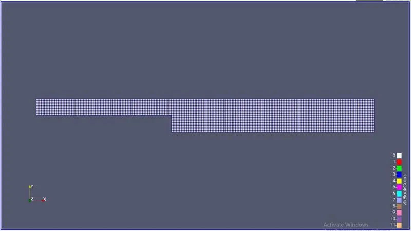
Here we didn't use any grading factor so the Mesh is uniform through out the model
Velocity Flow through the backward facing step geometry :-
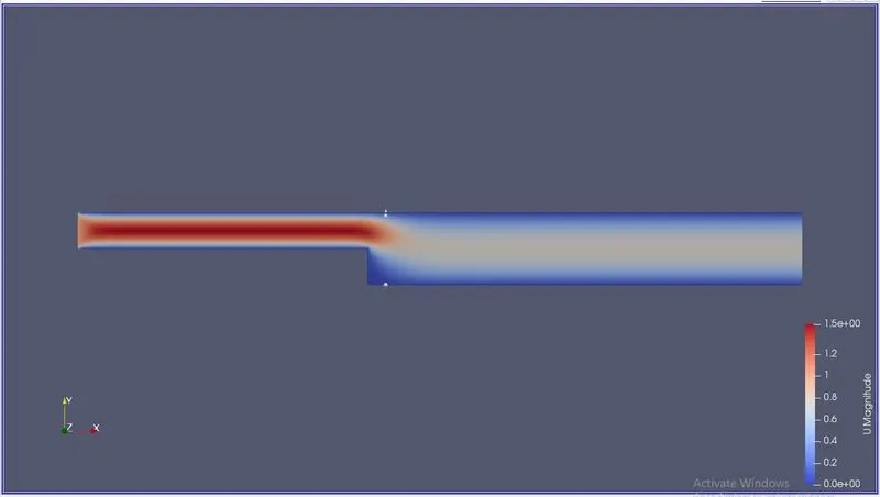
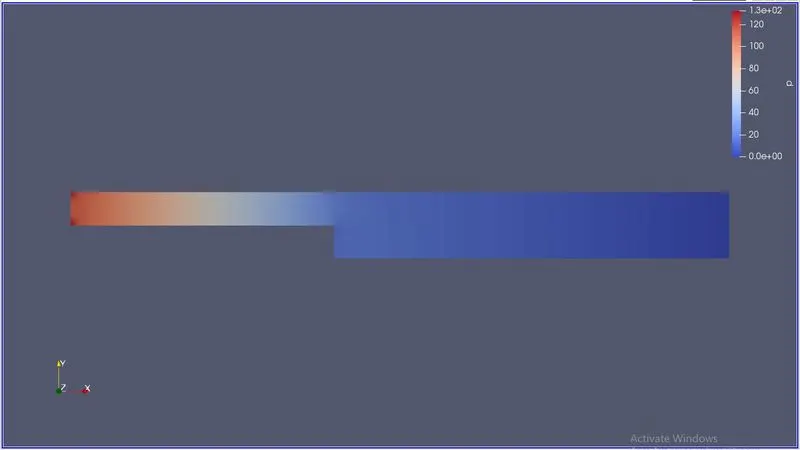
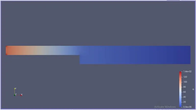
Pressure Flow through the backward facing step geometry :-
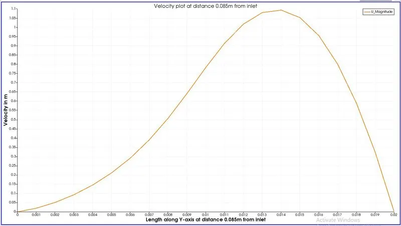
Velocity profile at a distance 0.085 from the inlet :-
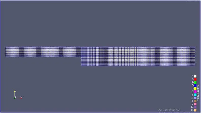
2nd case where we use grading factor as we get finer mesh at the walls :-
Mesh:-
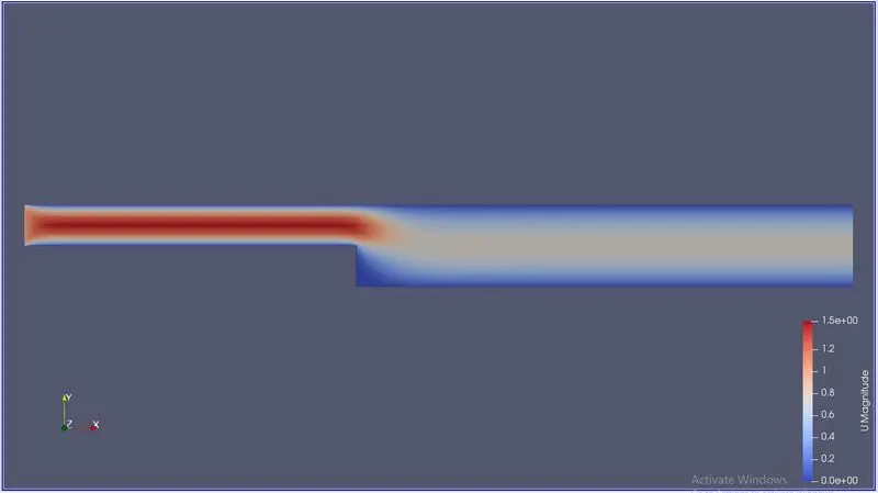
Velocity Flow through the backward facing step geometry :-
Pressure Flow through the backward facing step geometry :-
Velocity profile at a distance 0.085 from the inlet :-
Conclusion :-
1) From the simulation it is seen that fluid when going through the inlet to outlet the area increases, as area increases the velocity also decreased.
2) While observing the plots
when we take the first case the mesh is uniform throughout the geometry so the plot is also showing a normal curve.
When we take the second case the mesh is finer at the walls and courser at the middle. So we can see that the curve is smooth at the ends but seems like straight lines with bends at the middle because the mesh is coarser at the middle.
3) So it is clear that if we want to capture the results more accurately finer mesh is used.
why Grading/Growth factor is essential for meshing.
1) Grading factor = (size of the end cell)/(size of the starting cell)
2) Grading factor help us to adjest the size of the cell at the starting or at the end of the block.
3) So area where we need an accurate result we can put a finer mesh and area which are not much important we can use coarser mesh.
4) As said above the Grading factor help us to make the mesh finer and coarse, which in back give us a more accurate result while solving.