Week 4- Challenge
AIM:-
To create 1D elements of the given components with given cross section and degree of freedom
a. Rod element:- with only translational DOF and RBE2 link
Cross-Section: Box- Dimension a= 12 mm
Dimension b=10 mm
Thickness t= 0.75 mm
b. Beam element:- with all DOF and RBE3 link
Cross-Section: I Section- Dimension a= 8 mm
Dimension b= 10 mm
Dimension c= 8.5 mm
Thickness t1= 0.75 mm
Thickness t2= .6 mm
Thickness t3= .6 mm
c. Bar element:- with only x and y DOFs With RBE3 link
Cross-section: Cross section- Dimension DIM1= 5 mm
Thickness DIM2= 1.2 mm
Dimension DIM3= 10 mm
Thickness DIM4= 1.2mm
d. & e. Apply the mass of magnitude 10 with RBE2 link
f. Join the two components with Spring elements
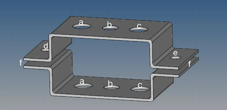
The 1D components should be in the respective places as shown in the above figure
PROCEDURE:-
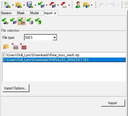
- Import the cad model into Hyper mesh
- By Import>Import Geometry
- Give File type as IGES
- Select the file from the folder
- Click on the file that appers in the window.
- Click on Import
- Now we need to make the mid-surface of the component
- Geometry>Mid surface> select the Part > Extract
- We need to give the each mid surface in two parts as 2 components
- For that Right click on component>Create>Give a Name
- Go to tools> Organize> Choose Surface>Select the surface to move to the new created component.
- Click on Move.
- Now we can see the mid surface moved to the newly created component.
- the midsurface is having the color of the newly added component.
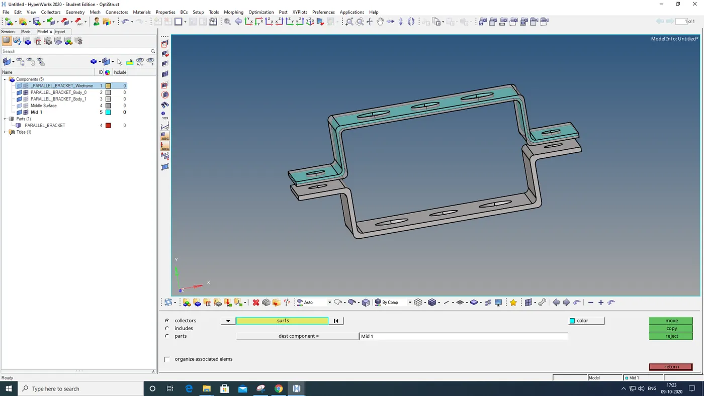
- Likewise do it for the other part also
- Now we only need these 2 mid surface, delete all other parts.
- Create a new material property.
- By right Click on the Model window>Create>Material
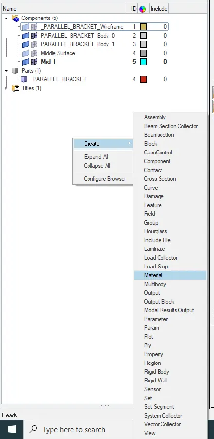
- Then in the window below edit the properties of the Material.
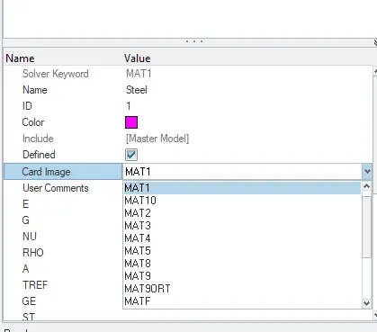
- Like wise also create property, properties for 2 Brackets, Rod, Beam, Bar.
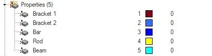
- Then we go to Geometry AutoCleanup.
- After that we start meshing of component.
- GO to 2D>Automesh> Give element length>Element type as Mixed>Mesh

- After Meshing check for any error and rectify the errors.
- After that we will start to give RBE2 and RBE3 elements on the hole regions.
- Go to 1D>rigids (For RBE2)

- Click on Nodes>By paths> select the nodes where you want to get the RBE2.
- Choose the Degree of freedom as we need > click on Create.
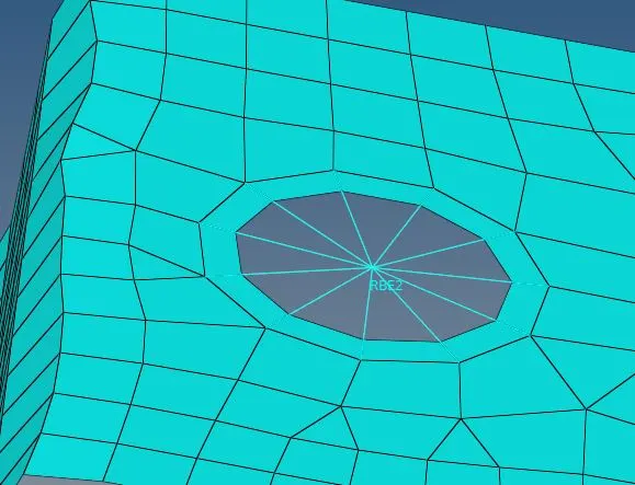
- Like the same 1D>RBE3> Select the nodes>Give neccessary degree of freedom>Create
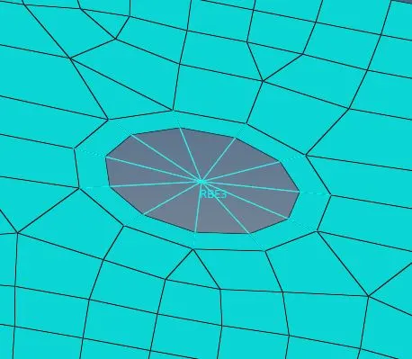
- To Make the Rod, Beam, Bar. We need to make the Crossection assigned.
- For that We need to go to 1D>HyperBeam>Standard section type As Thinwalled Box> create.

- In the coming window we can give crossection And also by right click in the Window on Left side. we can make I section and also cross. Also Assign the Dimensions
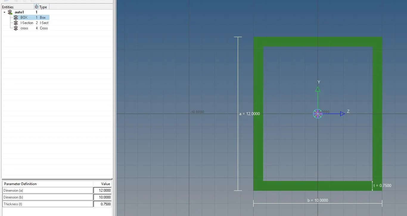
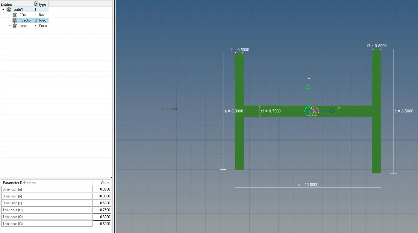
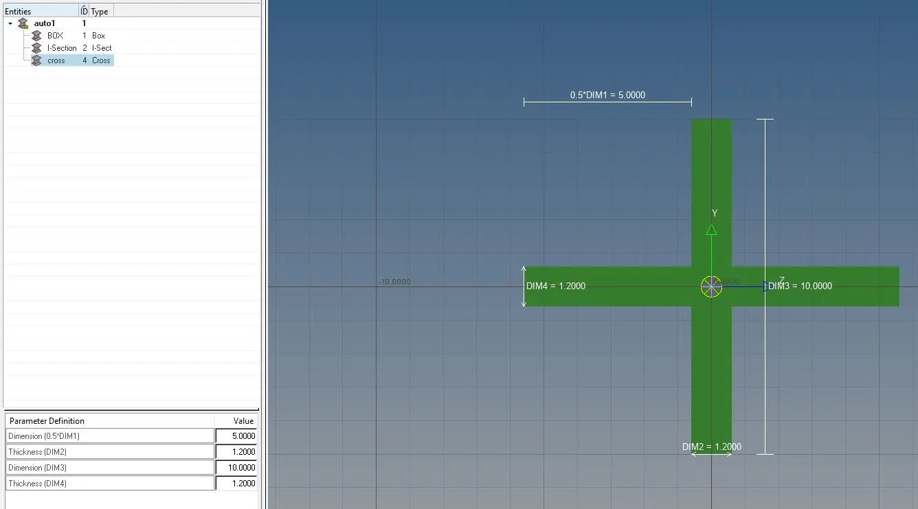
- After assigning the dimensions we can create the Bar ,Beam and rod
- For making Bar, Goto 1D>Bar

- Select the nodes through which we want the bar to form.
- Guide the crossection By selecting N1 & N2
- In property select Bar which we have setted earlier
- In element type select CBAR
- Press Tab button
- Like the same we can make Beam but in the element type choose CBeam
- Also change the property as Beam.
- For making Rod, 1D> Rod

- Choose the 2 nodes through which we need to get the rod.
- Select the property as Rod.
- Element type should be set to CROD
- Press Tab key
- To Give the mass on a point
- goto 1D > Mass

- Select the nodes where we want to give mass
- Give the Magnitude in Mass Column
- Select element type as CMASS1.
- Click on Create
- Now we can we can connect the two components with SPRING
- Goto 1D>Spring

- Select the two connection points of the spring
- Select Element type as CELAS1
- Press on Tab Key .
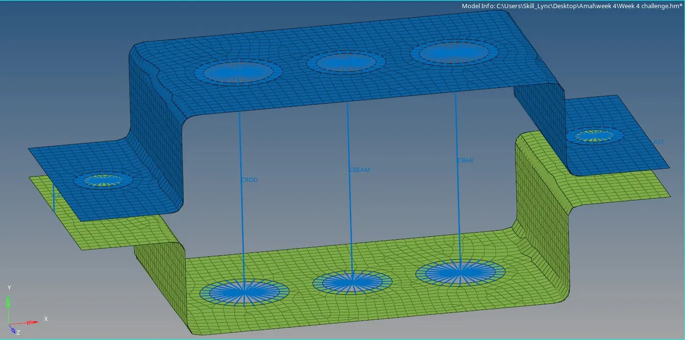
- We get the final result as this.
- To view the Rod , Beam an Bar in 3D, we change 1D traditional element Representation from tool bar to 1D detail element representation.
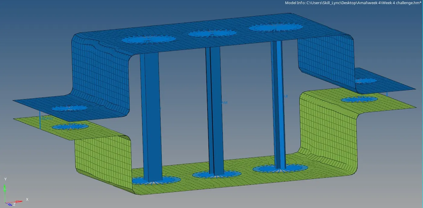
Result:-
The given CAD model is Meshed , the RBE2 and RBE3 with the necessary degree of freedom is created. The Bar, Beam and Rod is represented in 1D and the crossection is assigned with proper dimensions