Week 3
AIM:-
- To check for the geometrical errors for the "Car Hood".
- To mesh with the given element Quality criteria.
- After meshing the component the thickness has to be assigned.
PROCEDURE:-
1) IMPORTING THE CAD MODEL:-
- Open the ANSA software and import the cad geometry by clicking on File>Open>Browse the file from the list. Click OK.
- We can give the Length Parameter as 1 for the better visualization and to refine the model for our workability by going to Mesh Module, under Parameter tab click on Length. Give Length as 1.
- Perform the topo function to arrange the faces and geometry of the model by selecting the Topo Module>Faces>topo. then make a box selection over our geometry .
2)GEOMETRY CLEANUP:-
- After doing the topo, we can do the Geometry Check, by clicking on the Checks tool on Tools toolbar.
- From the window appearing, check in the check list as our requirement, it include options like Unchecked faces, Collapsed Cons, Triple Cons, Needle Faces etc. Click on EXECUTE.
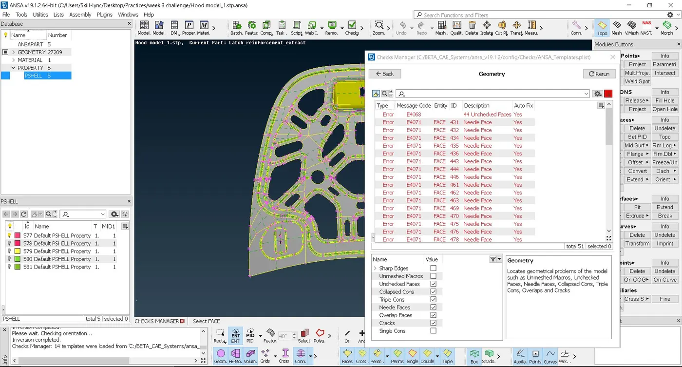
- The errors appered can be eliminated by Auto Fix, If the auto fix can't eliminate the error we should do it manualy , For example Triple cons should be eliminated by first releasing the con using Release option under Cons tab in Topo Module. Then again do the topo only with the proper cons.
- After clearing all the errors again do the Check.
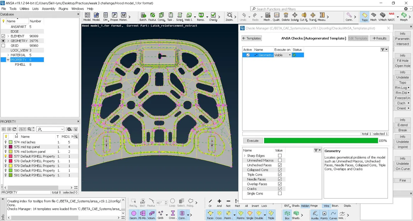
- IF the window shows 100% with a green strip then your geometry is ready.
3)MID-SURFACE GENERATION:-
- MID-SURFACE GENERATION OF OUTER PANEL
- For the mid surface generation we can use Mid.surface tool or the Offset tool in the faces tab in Topo module. Click on the midsurface or offset tool, select the faces to mid surface, give the required distance, middle click the mouse button. To select the whole faces in a single click use the option Features in the feature selection toolbar.
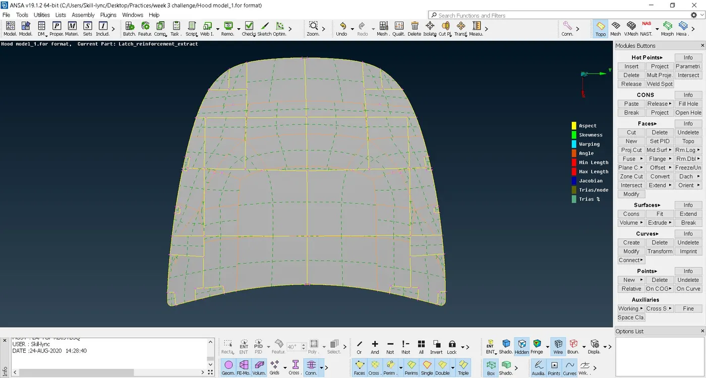
- After mid surface generation delete the unwanted curves and lines for good mesh generation. Also we can give lines and curves in a way that it will give us a good mesh flow.
- MID-SURFACE GENERATION OF INNER PANEL
- Mid surface of the inner panel is also made by using the tools Mid.surface or offset
- The selection using Feature option is more useful in this area due to more number of faces.
- Also a good amount of line modification is done in this panel cause of many curves,dip, fillet etc.
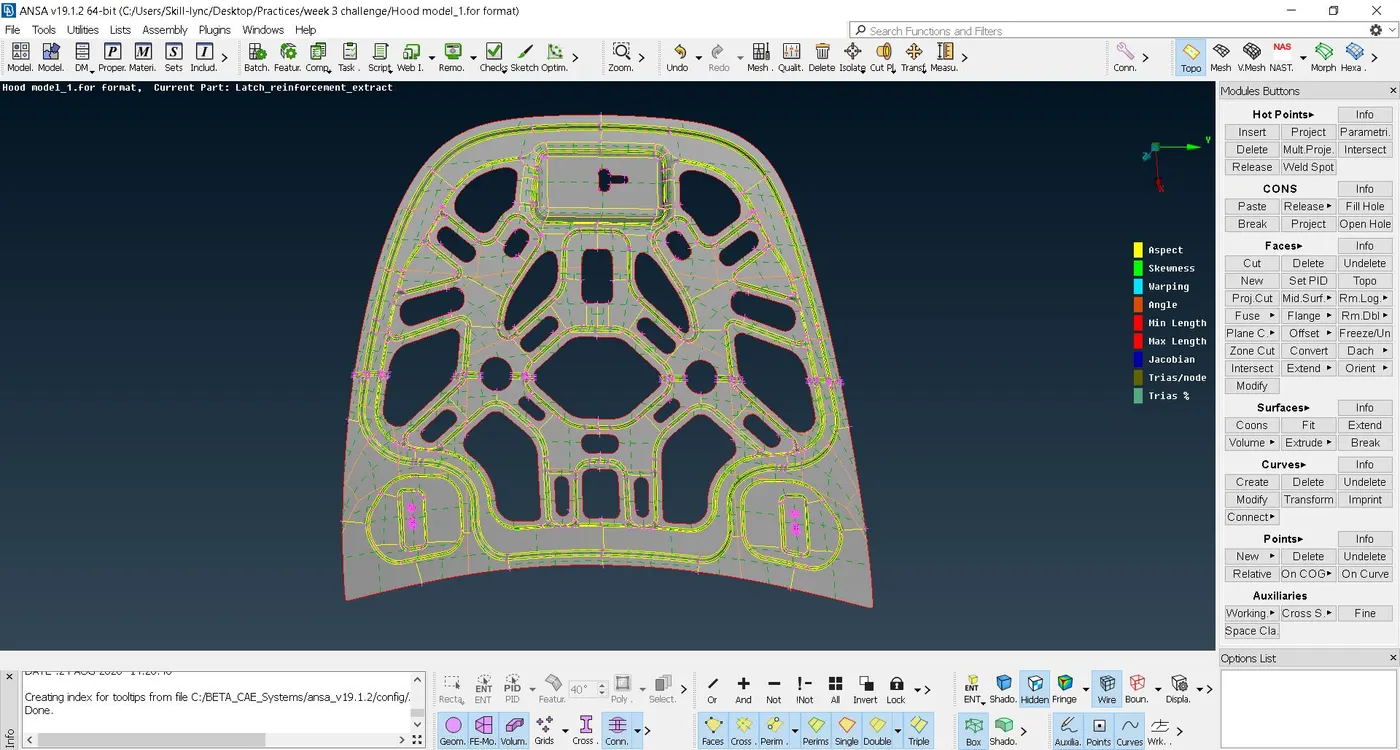
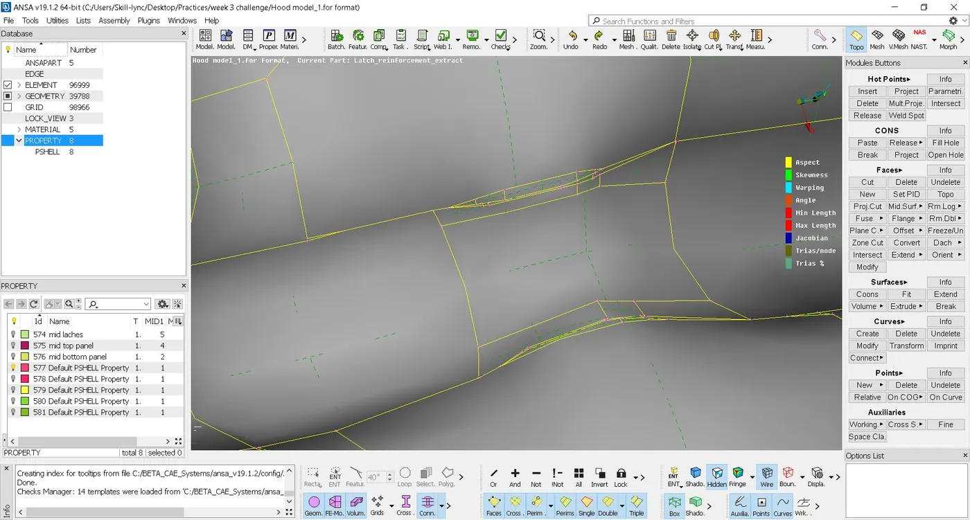
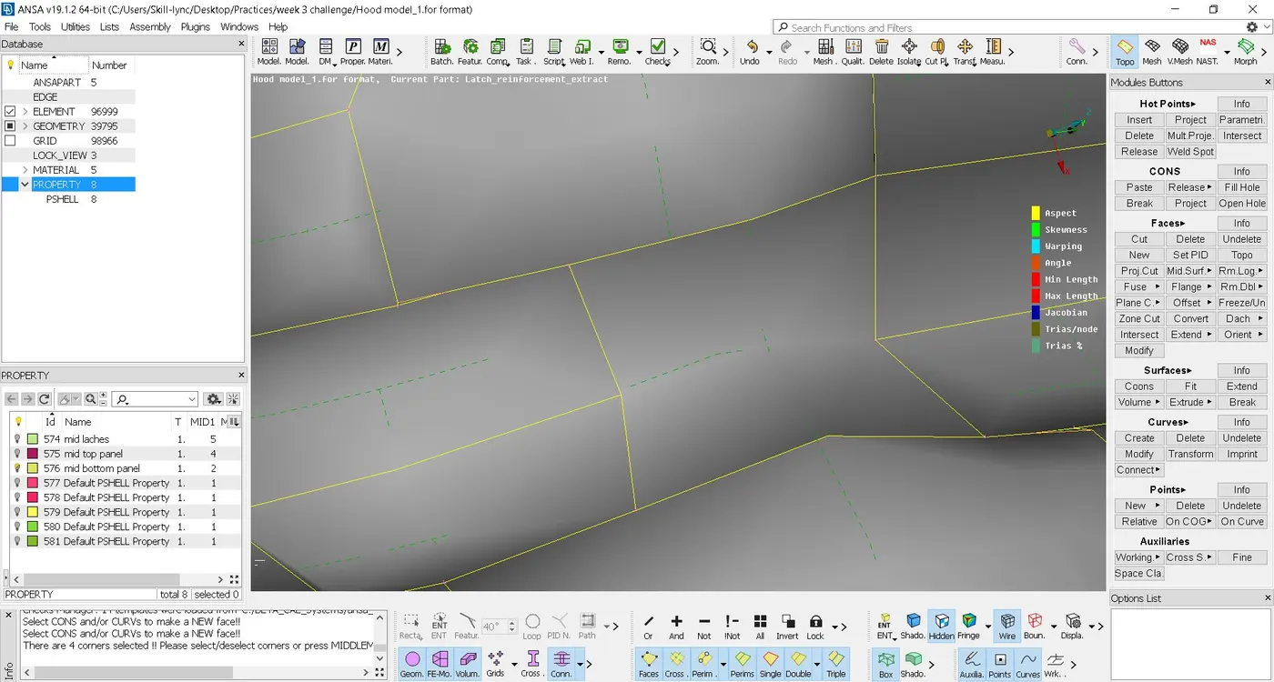
- MID-SURFACE GENERATION OF LATCH AND HINGE:-
- Also do the same with the Latch and Hinge for generating mid surface. After the midsurface generation of the 3 main parts . Set different properties for each part using Set PID in faces tab.
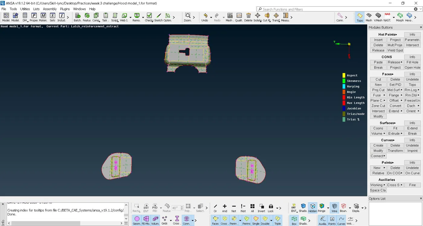
4) Meshing:-
- Before starting the meashing we should set the quality criteria. For that select Utilities tab and select Quality Criteria or F11. Set the criteria as our requirements.
Our Required Quality Criteria:-
-
S.No
Quality Criteria
Value
1
Target/Average length
5
2
Minimum Length
2
3
Maximum Length
7
4
Aspect
3
5
Warpage
15
6
Skewness
45
7
Jacobian
0.7
8
Minimum Quad Angle
45
9
Maximum Quad Angle
135
10
Minimum Tria Angle
30
11
Maximum Tria Angle
120
10
Tria Percentage
15
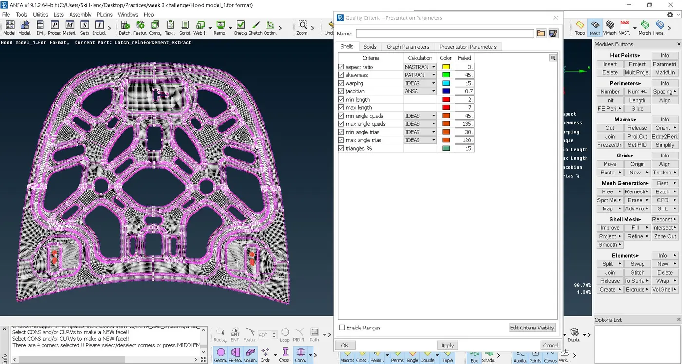
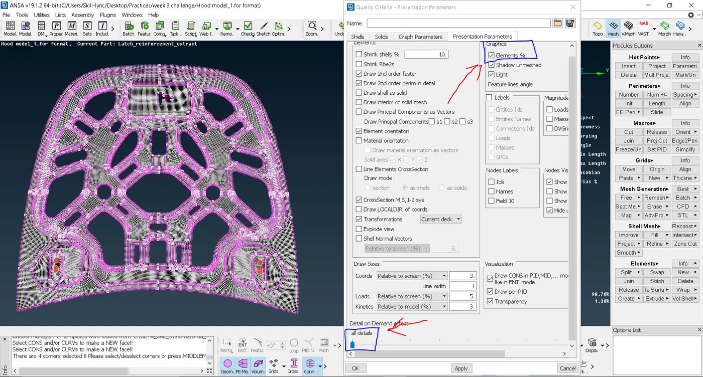
- Also in Presentation Parameter under Graphics check the element% and set the Details and Demand effect to all details
- Before starting the meshing process we need to select the delete in Hotpoints in Topo module. to delete the unwanted hotpoints and go to mesh module , select Length under perimeter tab in Mesh Module and give the target length.
- For meshing the Outer and Inner panel we can delete the half of the panel in a symmetrical way so that after done meshing on one of the half we can mirror the mesh to get mesh in the other half.
- For meshing a part we can use the Best option in the Mesh Generation tab. Click on Best, chose the face to mesh, middle click
- After meshing for getting a good quality mesh we can use the Reconsturction or smooth in the shell Mesh tab
- The quality of the mesh depends on number of rotating quads, trias and errors present. Reduce maximum number of trias , eliminate all rotating quads and errors
- most of the opposite trias can be eliminated using Split and Swap in Element tab, also by using Paste option in Grid tab
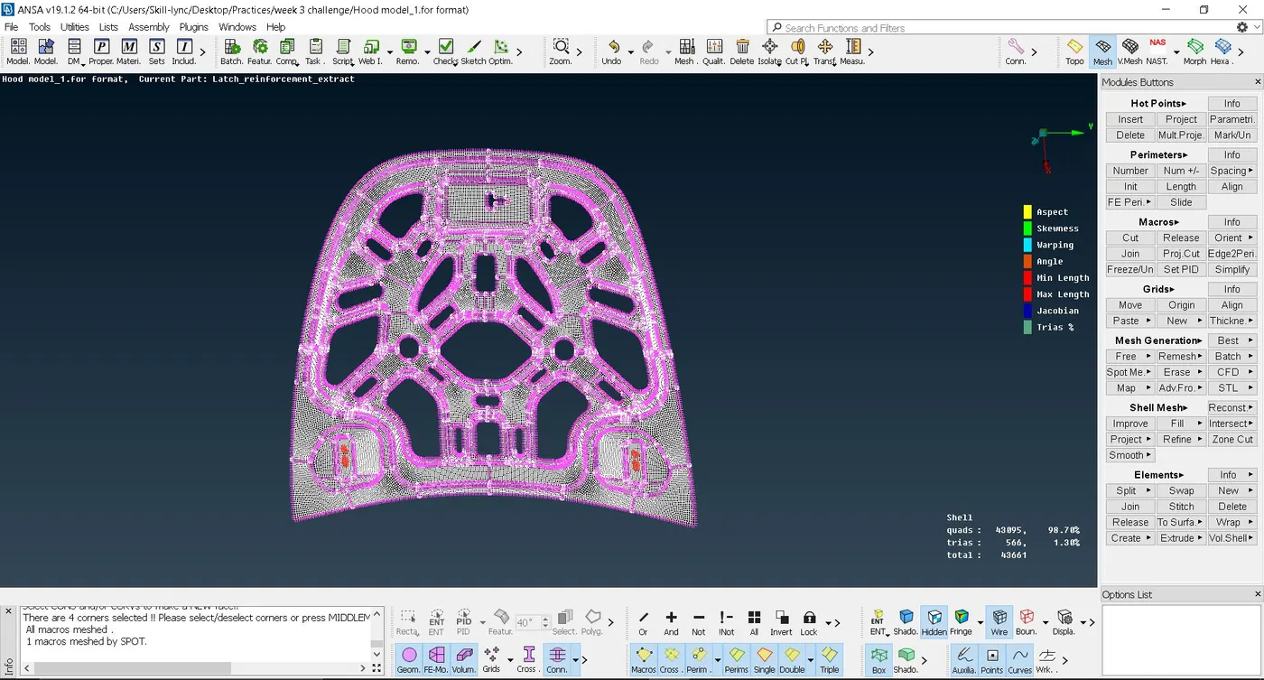
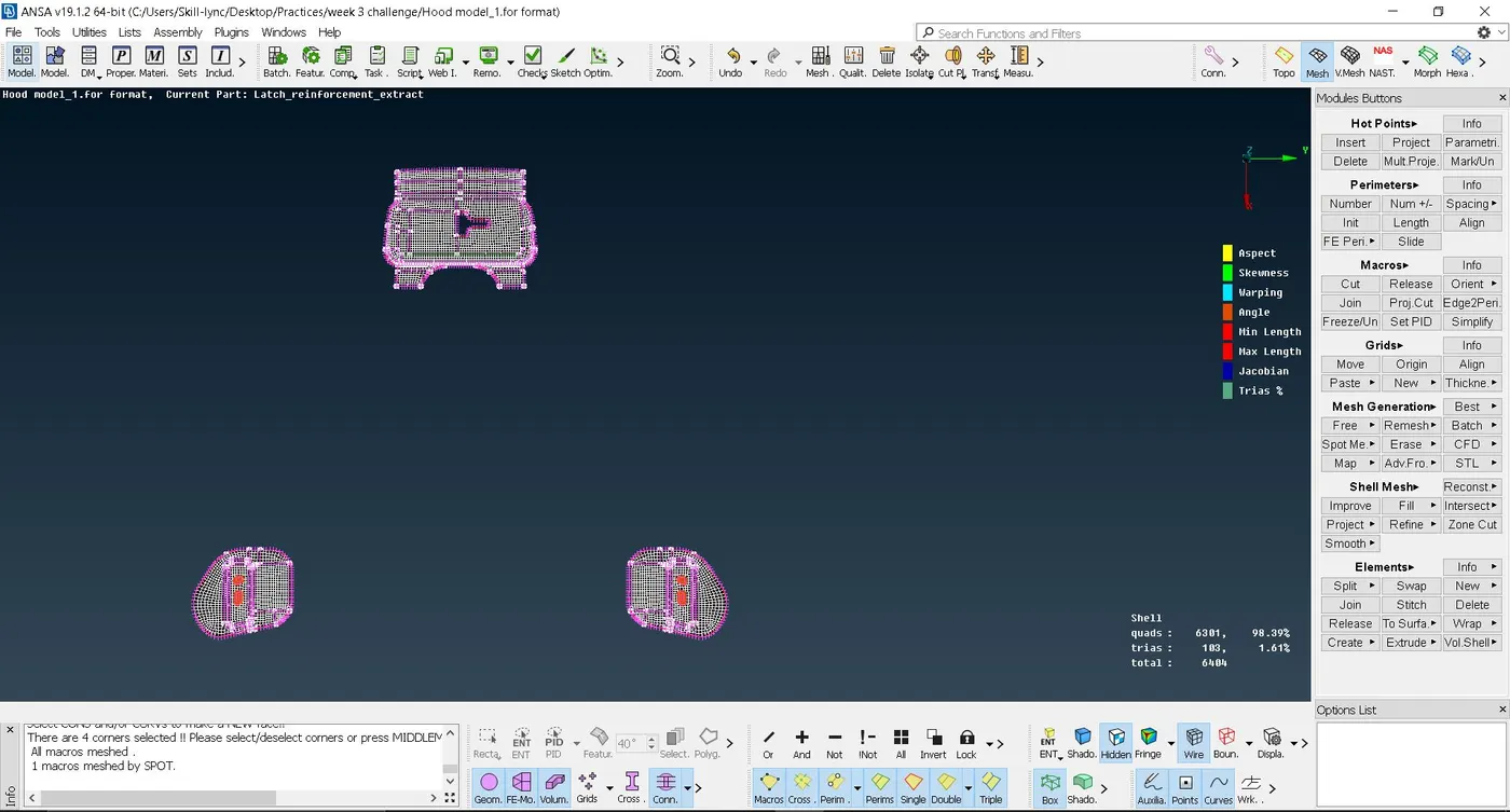
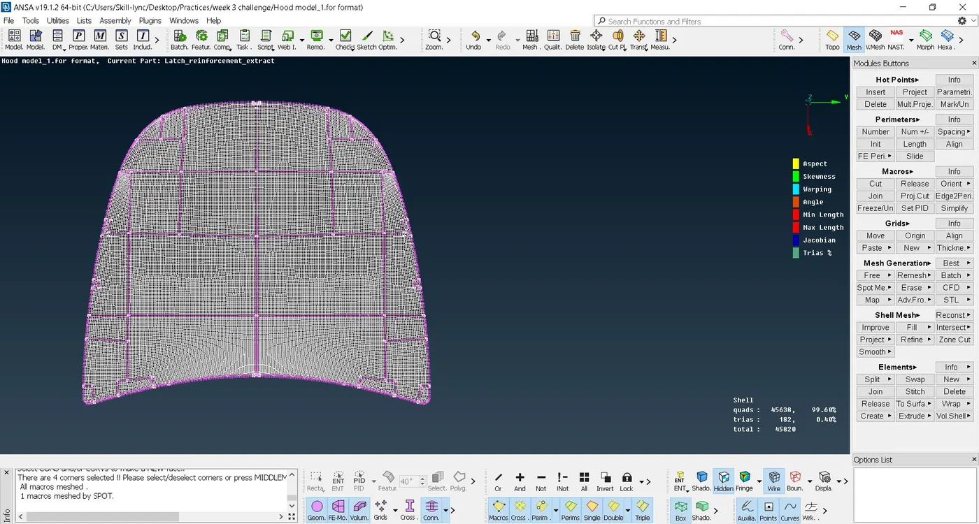
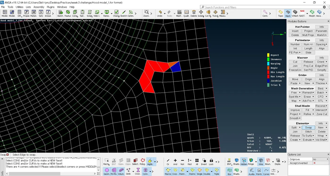
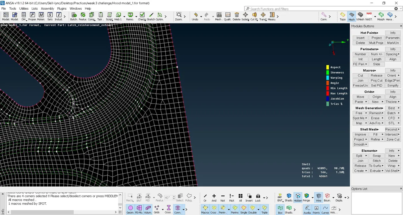
After the meshing , the elimination of errors is done and the off elements and unmeshed elements are zero. We can now assign the thickness to the parts by double clicking on each parts property and giving the original thickness of the parent geometry.
5) LEARNING OUTCOMES:-
- I learned about different tools in ANSA.
- I have learned to cleanup a geometry for meshing.
- Learned to make mid surface of simple and complex parts.
- Learned to mesh a geometry.
- By doing the hood I have learned how to eliminate errors and trias in different situations by using reconstruct, smooth, split, swap and paste.
6) CONCLUSION:-
- All the geometrical errors are rectified. The part was meshed and it is having 99.09% of quads and 0.91% of trias.
GOOGLE DRIVE LINK:-
https://drive.google.com/file/d/15FCBO1gQ5Rr-fZdK_g_TAPjqlCFW7h8_/view?usp=sharing