Week 2 - Converging diverging nozzle
SIMULATION OF CONVERGING-DIVERGING NOZZLE:
1 INTRODUCTION:
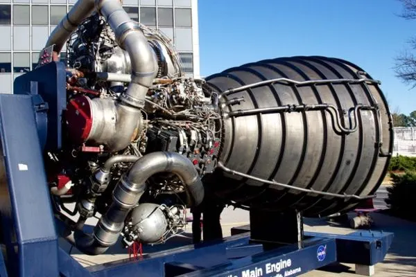
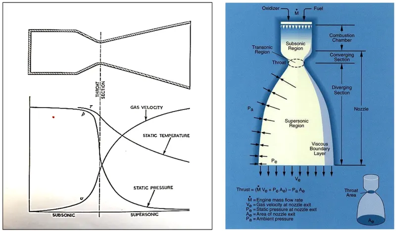
The best application of a converging-diverging nozzle is found in the rocket engine for space shuttles. These engines produce around 4,00,000 pounds of thrust which lifts the entire launch vehicle. A combustion chamber is present which feeds the hot high-pressure gas into a convergent duct that transitions to the divergent duct. The whole rocket engine nozzle from the combustion chamber to the exit is a convergent-divergent nozzle. For aeronautical studies, the characteristics of rocket engines, jet engines, supersonic and hypersonic wind tunnels etc. The details of the flow field including shock wave and expansion wave patterns are studied using two choices. To conduct flight tests using the actual vehicle and run wind tunnel tests on a small scale model of the vehicle. Flight tests although providing the final answers in the full-scale environment are costly and dangerous if the vehicle is proven unsafe. Hence the vast bulk of supersonic aerodynamic data have been obtained in wind tunnels on the ground.
2 THEORY OF CONVERGING-DIVERGING NOZZLE:
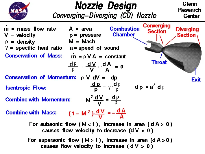
From the above area-velocity relation, the shape of the nozzle and the diffuser combining to form the supersonic wind tunnel is determined.
For `0<=M<=1`subsonic flow, the quantity inside the parenthesis is negative. Hence an increase in velocity (positive dV) is associated with a decrease in area (negative dA). A decrease in velocity is associated with an increase in area. Clearly, for a subsonic compressible flow, to increase the velocity, there has to be a convergent duct. and to decrease the velocity, there has to be a divergent duct. This in qualitatively similar to incompressible flow.
For M>1 supersonic flow, the quantity in the parenthesis is positive. Hence an increase in velocity (positive dV) is associated with an increase in area (positive dA). Likewise, a decrease in velocity is associated with a decrease in area. For a supersonic flow, to increase the velocity, there must be a divergent section and to decrease the velocity, there must be a convergent duct. This is the direct opposite logic for subsonic flow.
For M=1 sonic flow, dA=0 even though a finite dV exists. Mathematically, this corresponds to a local maximum or minimum in the area distribution. Physically it corresponds to a minimum area. When M=0, we have dA/A = - dV/V which integrates to AV = constant. This is the familiar continuity equation for incompressible flow in ducts.
A gas is taken at rest and isentropically expanded to supersonic speeds. The above results show that we must accelerate the gas subsonically in a convergent duct. As soon as sonic conditions are achieved, the gas is further expanded to supersonic speeds by diverging the duct. Thus a nozzle designed to achieve supersonic flow at its exit is a convergent-divergent duct. The minimum area of the duct is called the throat. whenever an isentropic flow expands from subsonic to supersonic speeds, the flow must pass through a throat; moreover, in such a case, M=1 at the throat. The converse is also true; if we wish to take a supersonic flow and slow it down isentropically to subsonic speeds, we must first decelerate the gas in a convergent duct, and then as soon as sonic flow is obtained, we must further decelerate it to subsonic speeds in a divergent duct. hence the convergent-divergent duct is operating as a diffuser. Whenever an isentropic flow is slowed from supersonic to subsonic speeds, the flow must pass through a throat; moreover, in such a case M=1 will be at the throat.
3 SIMULATION:
3.1 Preparing the geometry:
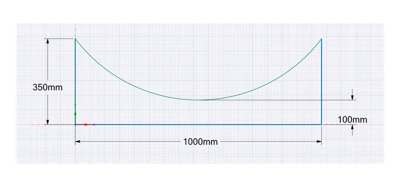
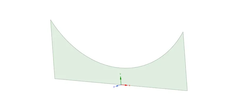
The lateral section of the nozzle is designed in Space claim. A 2D geometry is made on the XY plane. Since the geometry is symmetric it is sufficient enough to simulate half section of the geometry. By using axis-symmetric option in fluent, the results are accurate enough to compare with the full geometry flow studies.
3.2 Meshing the geometry:
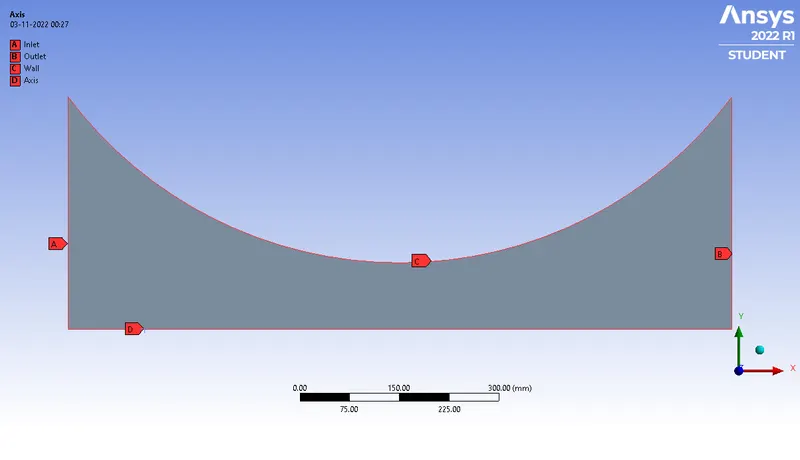
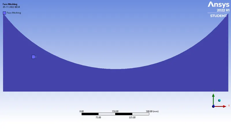
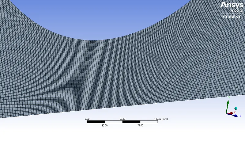
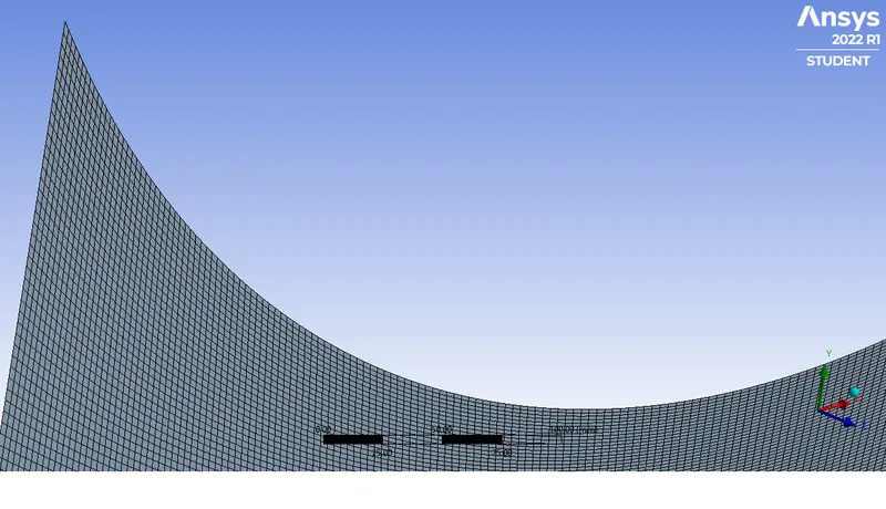
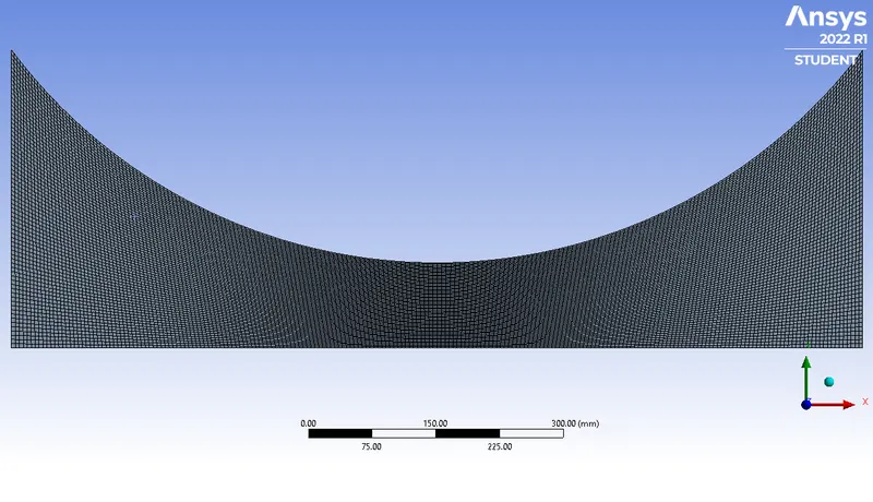
The edges are named inlet, outlet, wall, and axis respectively. The face meshing is done on the 2D geometry. Mesh element size of 5mm is given with a curvature effect.
3.3 Solving in Fluent:
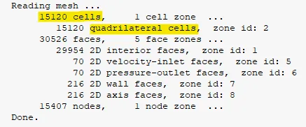
15,120 quadrilateral cells are formed in the geometry.
3.3.1 General solver properties setup
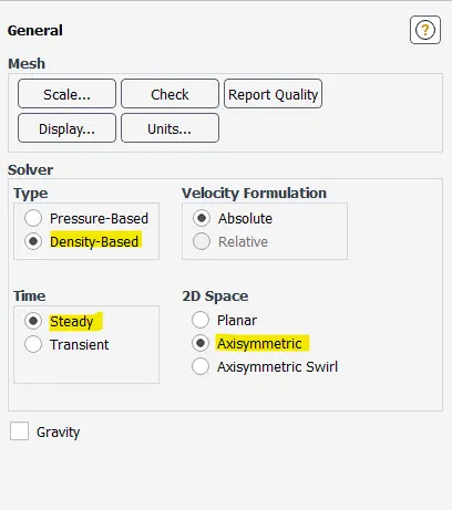
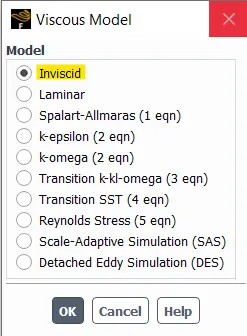
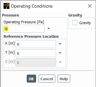
A density-based solver with axisymmetric space is defined. An inviscid model with 0 Pascal as operating pressure is set.
3.3.2 Setting up the boundary conditions
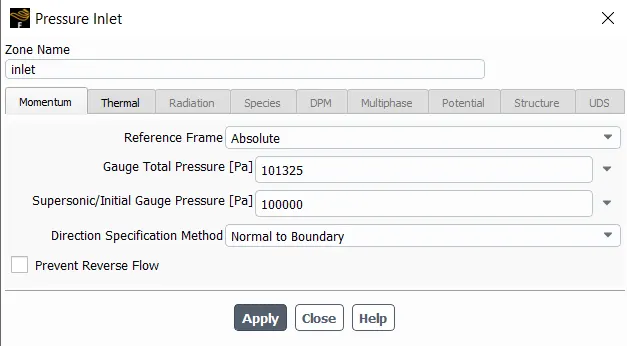
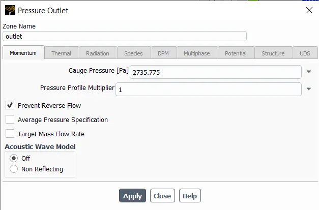
A pressure inlet and pressure outlet is defined with 0 atm or 101325 pascal at the inlet and 0.027 atm or 2735.775 pascal at the outlet respectively.
3.3.3 Setting the material properties
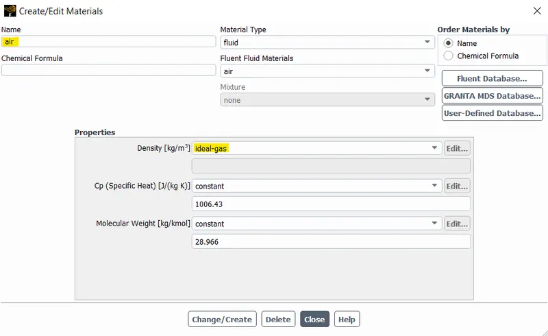
The material is set to ideal gas, as the material air has a constant density. The ideal gas has variable density and goes in with the density-based solver.
3.3.4 Defining contours for post-processing
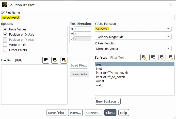
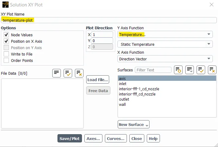
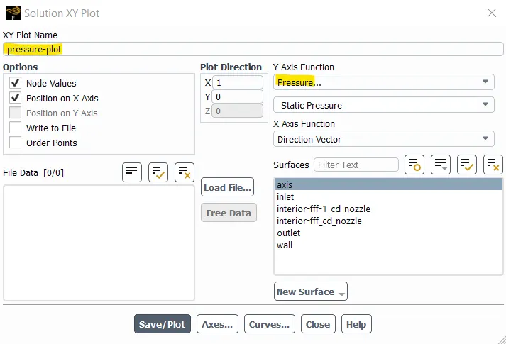
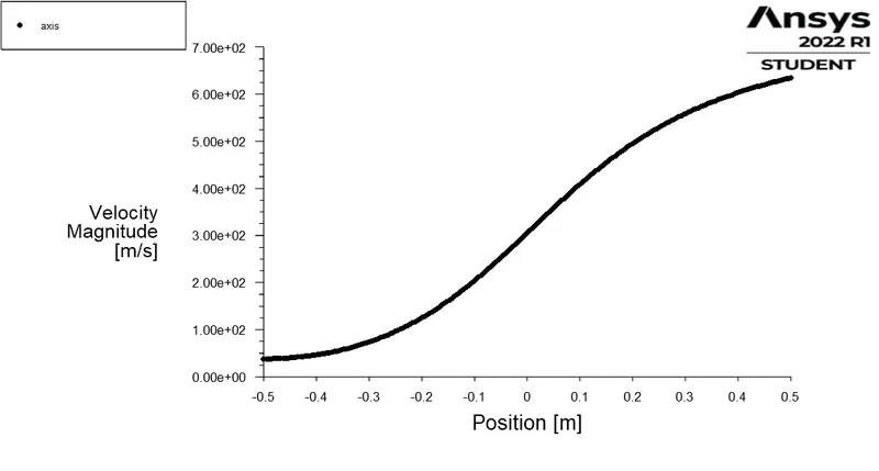
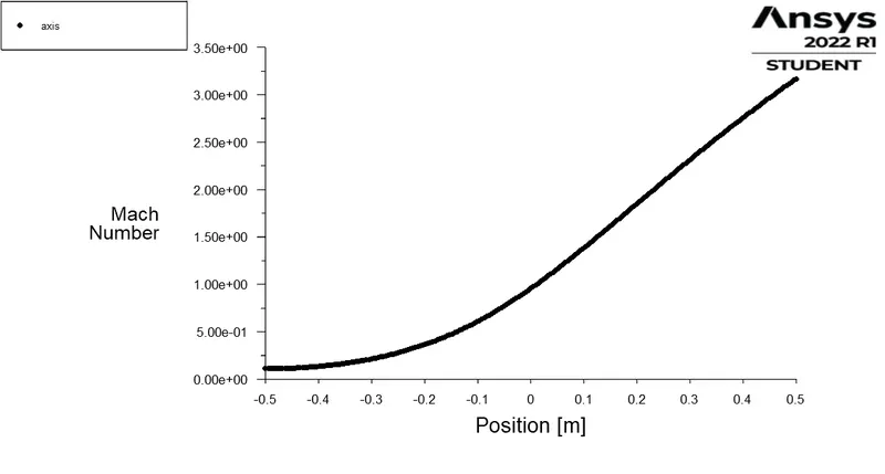
X-Y plot is defined for temperature, velocity, pressure and Mach number with X-distance on the x-axis and the properties on the Y-axis.
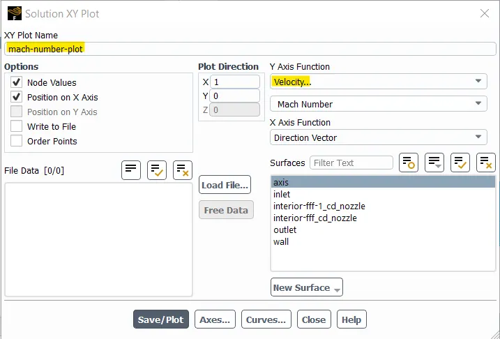
3.3.5 Defining plots for post-processing
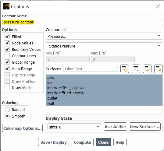
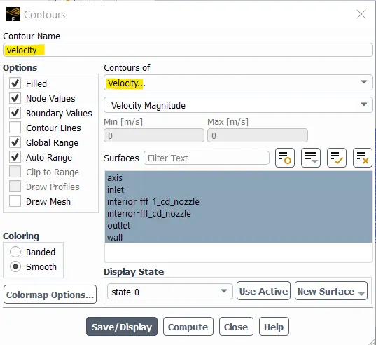
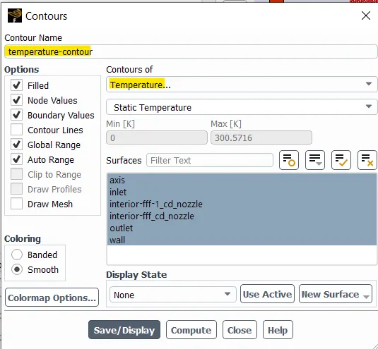
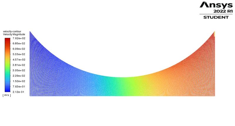
Contours for temperature, velocity and pressure are defined for a visual representation of the results.
4 RESULTS:
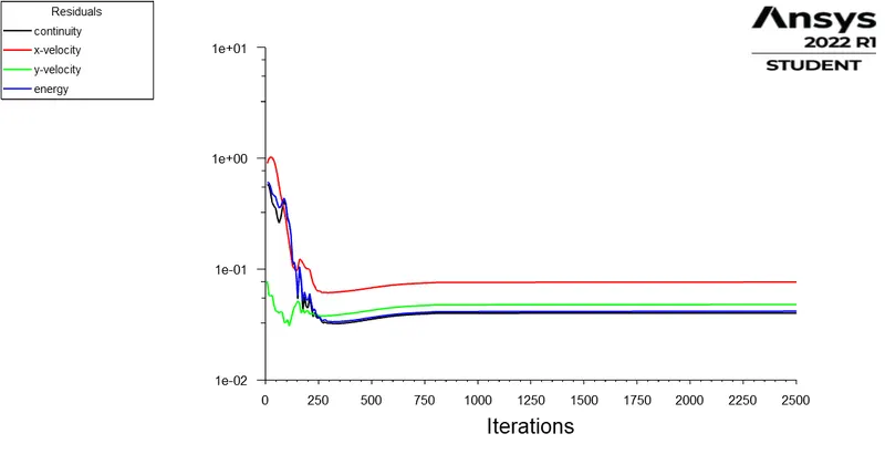
4.1 Residuals plot
4.2 Velocity plot
4.3 Mach Number plot
4.4 Pressure plot
4.5 Temperature plot
5 INFERENCE:
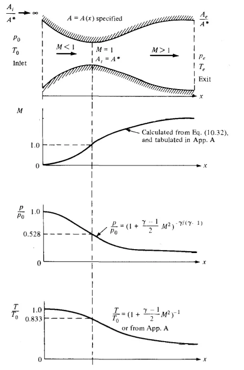 |
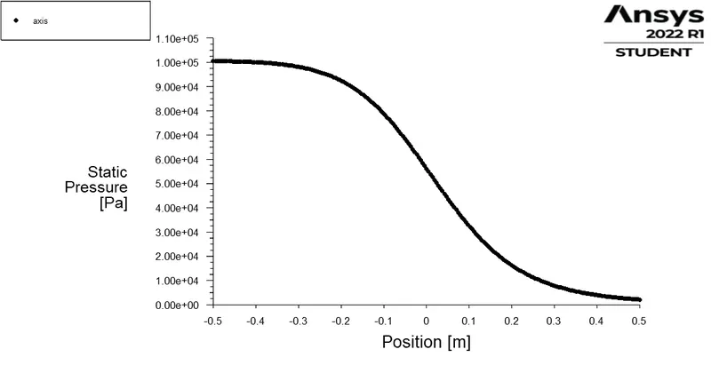
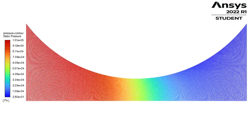
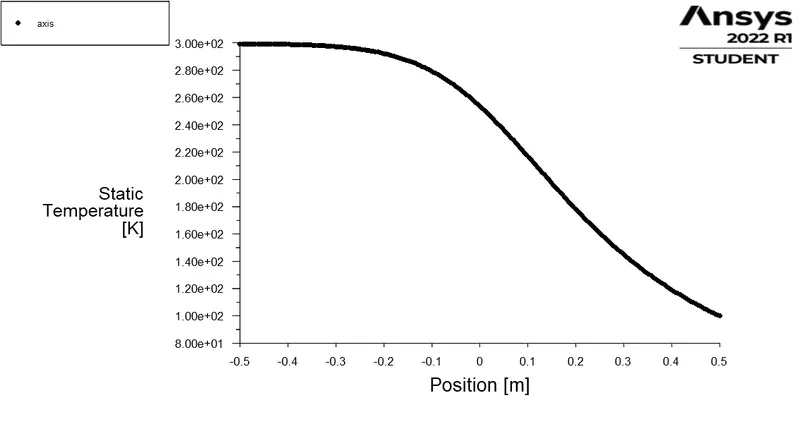
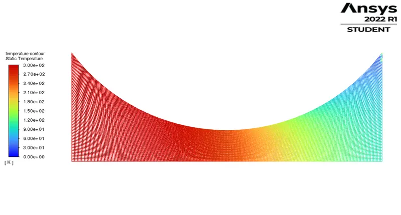
From the results, it is evident that the match number at any location in the nozzle is a function of the area at the location. And the match number is seen reaching 1, sonic condition at the midpoint of the nozzle, which is the throat. The midpoint is the throat and is observed as the location of minimal area. The velocity plot shows that the velocity rises from the convergent to the divergent section validating the Mach number plot. The pressure plot explains the minimum gradient given at the inlet as momentum and the steady rise of the pressure across the nozzle. The temperature seemed to be reduced at the exit section of the nozzle as per the relation. Theoretically the relation of the isentropic process and inviscid compressible flow is observed from the curves and the relation. This curve and relation is in accordance with the simulation results obtained from Ansys fluent. There has to be force imposed on the gas in order to provide a momentum which accelerates the gas. For inviscid flows, the only mechanism to produce an accelerating force on a gas is a pressure gradient. Hence, a pressure gradient is created at between the inlet and outlet. The exit pressure is maintained less than the inlet pressure which makes the gas flow through the nozzle. The axisymmetric approach of the solver is efficient since it reduces a lot of computing efficiency while not compensating on the accuracy of the results. The density based approach is used to have a flow where the density is not constant, which is compressible in the operation. The mesh has a curvature effect at the mid point which is the throat. This gives more accuracy to the results. |
6 CONCLUSION:
Thus the convergent-divergent nozzle is simulated in the fluent solver, with a minimally sufficient mesh structure. The geometry used is axis-symmetric and a section of the original geometry which is a model of the Application, The supersonic wind tunnel. The results are found in accordance with the theoretical results and the suitability of the solver is thus studied.
7 REFERENCE:
Fundamentals of Aerodynamics, Sixth edition, John D Anderson,Jr.