Week 4 Challenge : CFD Meshing for BMW car
MESHING OF BMW CAR:
1 AIM: To perform surface meshing of the given BMW M6 car model after topology cleanup, and place the car in a wind tunnel by creating one, Finally performing a volumetric mesh in the space between the tunnel and the car.
2 INTRODUCTION:
The primary challenge in conducting aerodynamic CFD simulations if actual vehicles with realistically complex geometry has been the construction of a computational mesh. The CAD to mesh processes used to date have been laborious, often requiring many weeks of engineering time. The surface meshing step starts with geometric representation of the domain boundaries in basic CAD, CAD-neutral or raw faceted format. For an aerodynamics or thermal management simulation, this includes the wind tunnel walls, road, inlet, outlet and the entire vehicle surface including all details such as exterior surfaces, mirrors, grills, powertrain, transmission, suspensions and others.
As a first step in performing a CFD simulation an analyst collects CAD models of vehicle parts and sub-assemblies from a central database and puts together a geometric representation of the vehicle. Such a geometric representation typically has numerous flaws that cause problems in the surface mesh generation process.
These typical problems include
- Small gaps in tolerance issues
- Small gaps in parts missing
- Small gaps in translation issues
- Thin objects
- Zero thickness surfaces
- Overlaps
- Intersections
- Proximity
- Small details
- Un-wetted surfaces
- External and internal details
These problem has to be rectified before forming a surface mesh then moving to a volumetric mesh, which results in an accurate CFD application.
Wind tunnel:
wind tunnel testing of full/model-scale components is a widely employed technique that guides detailed design decisions in thermal-fluid systems and allows for fundamental research of fluid phenomena. Many instances occur where theoretical and/or computational techniques are inadequate, either due to the complexity of the problem or the lack of suitable computational resources. Wind tunnel testing often serves as the most cost-effective approach for these reasons, as well as the expenses evolved in many forms of full-scale testing which can be related to wind-tunnel tests through appropriate parameter matching. Wind tunnels are extensively used in research institutes, universities, industry and governmental agencies for a wide variety of applications and can be classified in many ways.
3 PROCEDURE:
3.1 Initial geometry preparation:
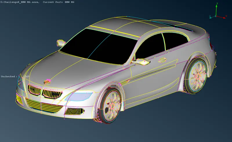
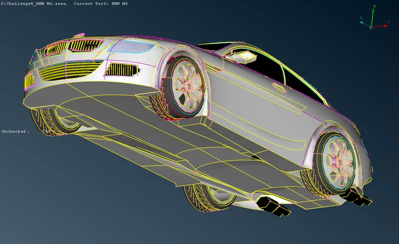
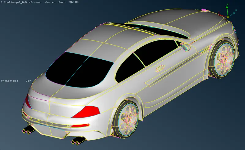
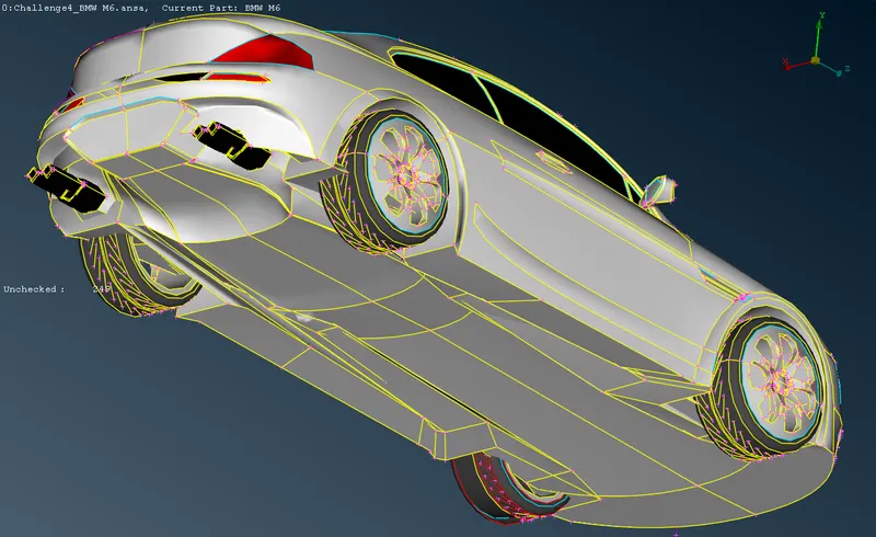
3.1.1 Defining cons resolution:
The cons resolution in the initial geometry has an irregular length which distorts the original geometry. Hence Perimeter>length and Macro>length tool in the mesh deck is used to define 1mm as the length of all the entities.
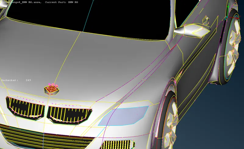
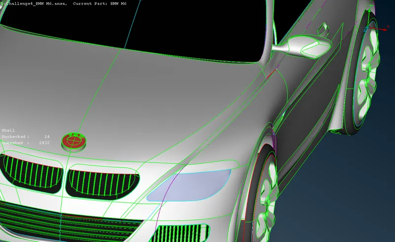
The image on the left has low resolution, while the image on the right has the perfect resolution.
3.1.2 Geometry split up by symmetricity:
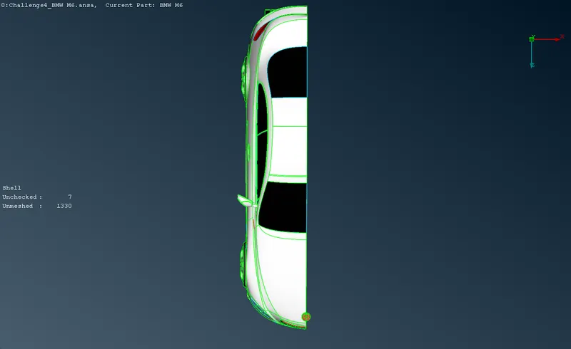
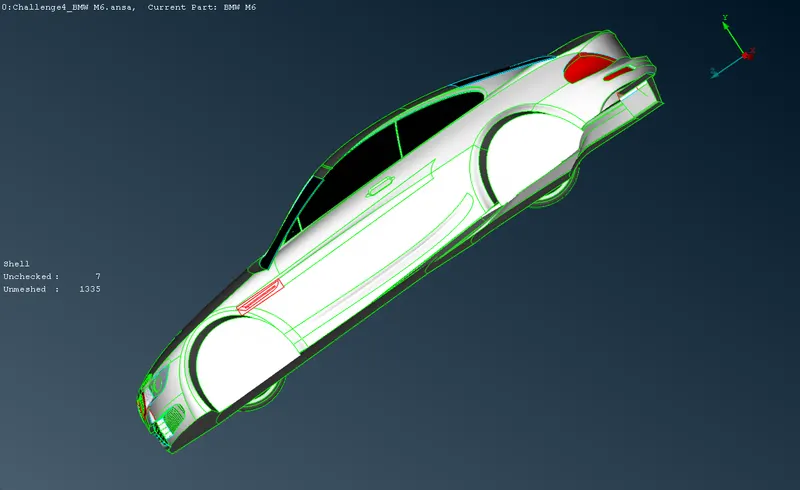
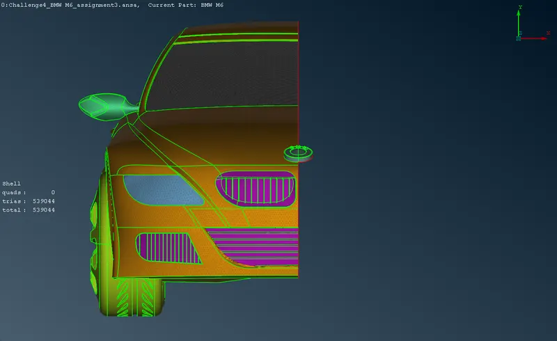
For ergonomic efficiency, the entire geometry is split into half on YZ plane, since the geometry is perfectly symmetric. The BMW hood ornament alone is kept as a full geometry as it is not a symmetric part.
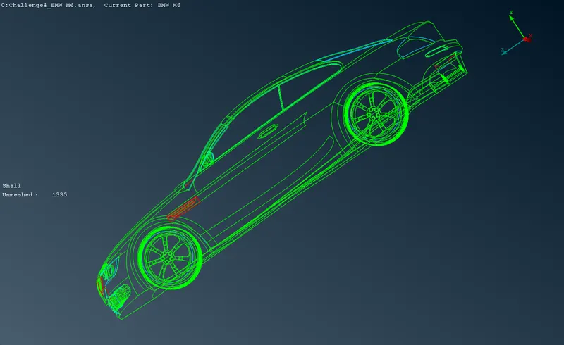
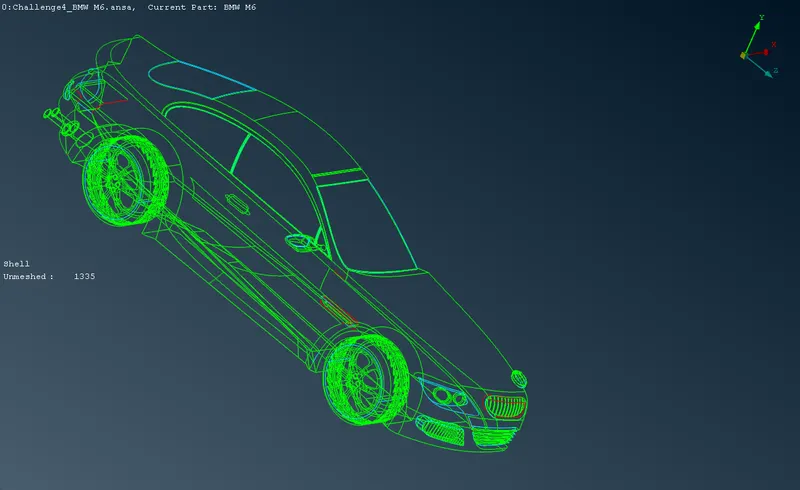
3.2 Topology cleanup:
| Before cleanup | Tools and methods | After cleanup |
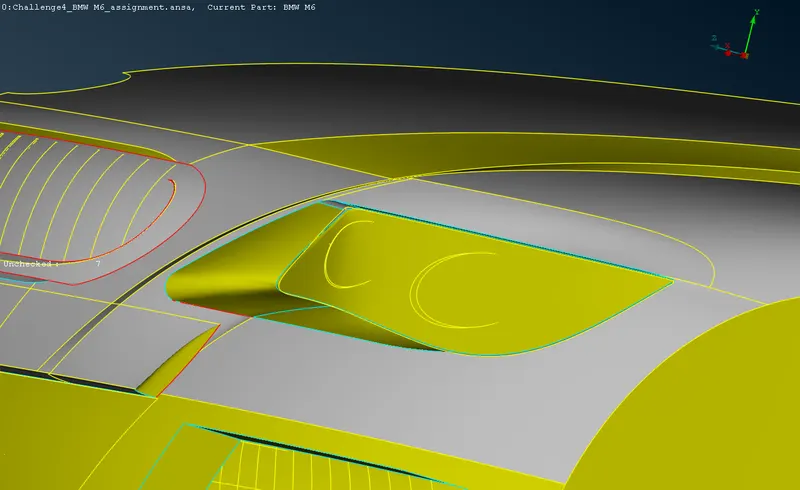 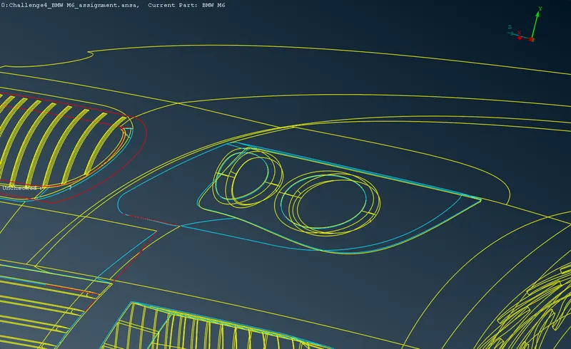 |
Unwanted surfaces and all the interior features are deleted in order to get rid of triple cons which would form a separate volume. Only one surface remains which form the head light of the car. |
|
|
|
The front grill is converted from a separate body with intricate features to a single surface, with single cons at the cutting plane edge. |
|
|
|
The ribs geometry of the grill is preserved and the backside surfaces removed. The front surface is kept constant and the ribs are built on this surface. |
|
|
|
The engine cover grill is also done by the same method to retain its features from the outside while breaking down to a single surface from the inside, removing all the single and triple cons. |
|
|
|
The side vents are carefully made into a proper shape which is projected outside and is integrated to the common volume inside. | 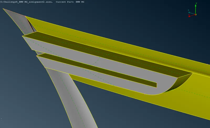 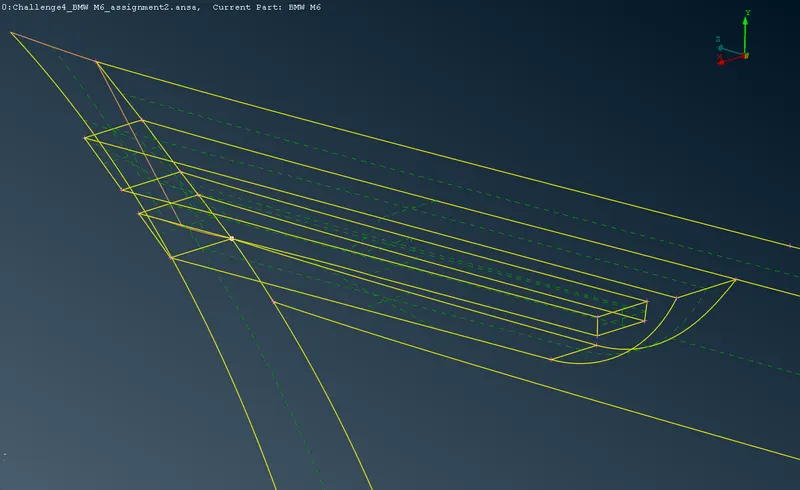 |
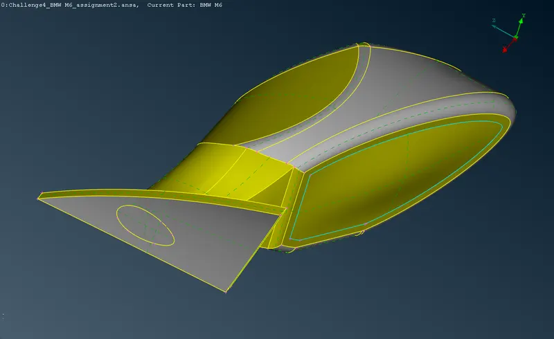 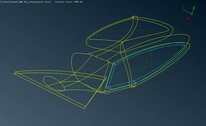 |
The triple cons and the inlet circular surface alone is eliminated which makes the rear view mirror. | 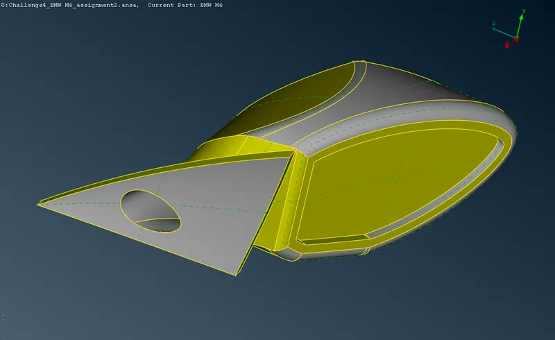 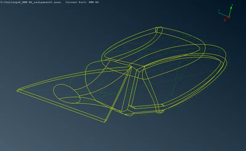 |
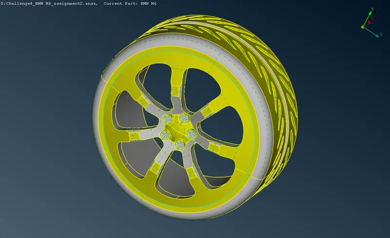 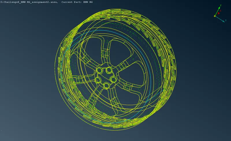 |
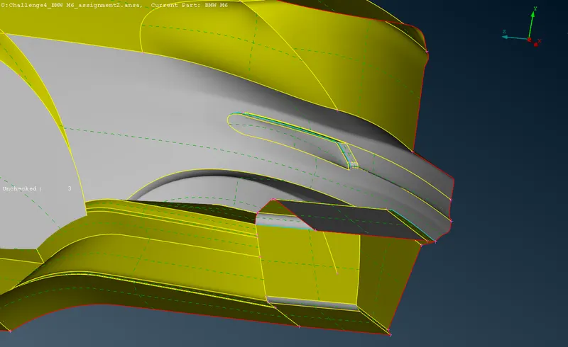
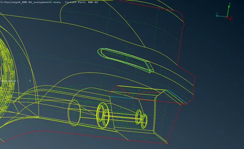
The entire rim and tyre in the front is made into a single volume by deleting the surfaces inside the side walls which forms the triple con. The same is done for both the front and rear tyres. | 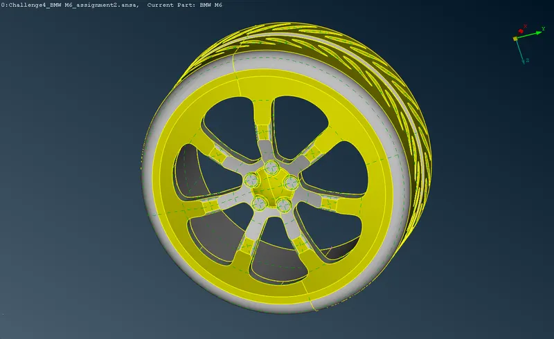 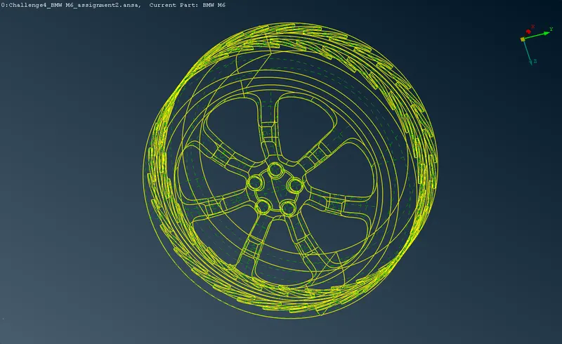 |
  |
The light assembly is made into a single surface same as the front light, by omitting all the features which are interior to the body skin panels; which avoids the triple cons. | 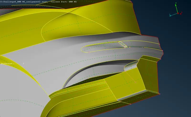 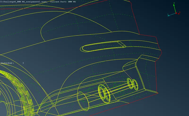 |
|
|
The entire rim and tyre of the rear is made into a single volume by deleting the surfaces inside the side walls which forms the triple con. The same is done for both the front and rear tyres. | 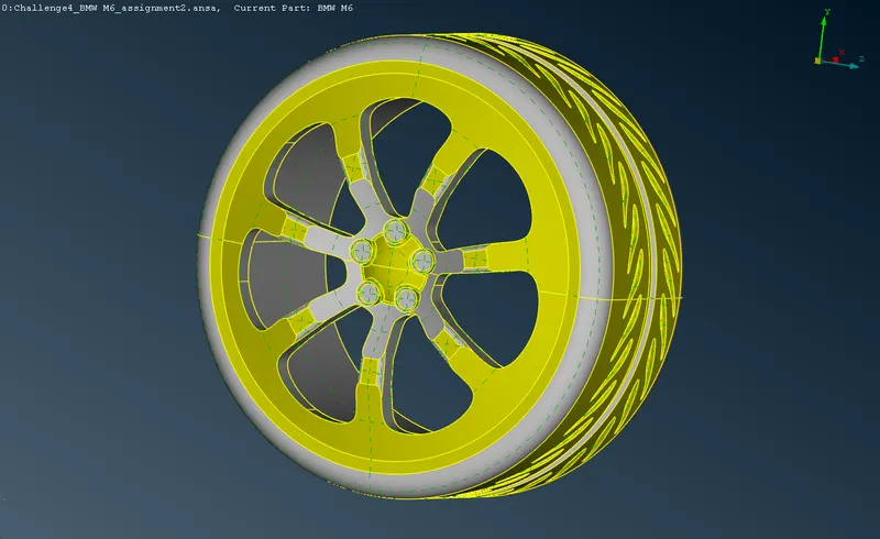 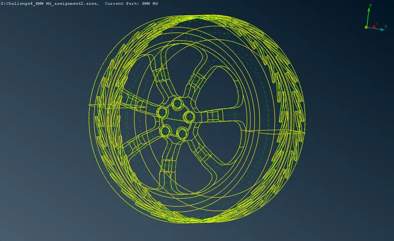 |
|
|
The underplate of the car is a complex surface which is made by a combination of many surfaces also keeping in mind, the surfaces should be free from sharp and needle surfaces. |
|
|
|
The underplate of the car is a complex surface which is made by a combination of many surfaces also keeping in mind, the surfaces should be free from sharp and needle surfaces. |
|
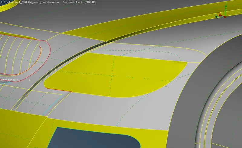
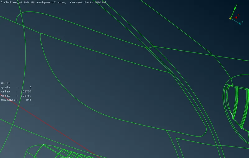
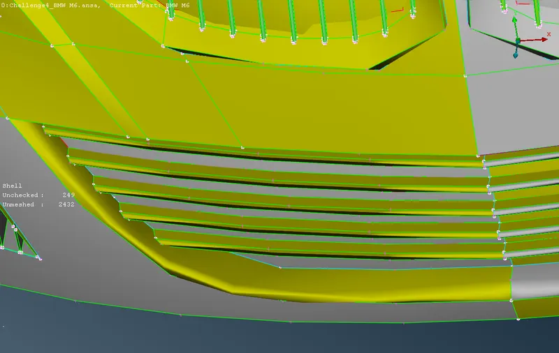
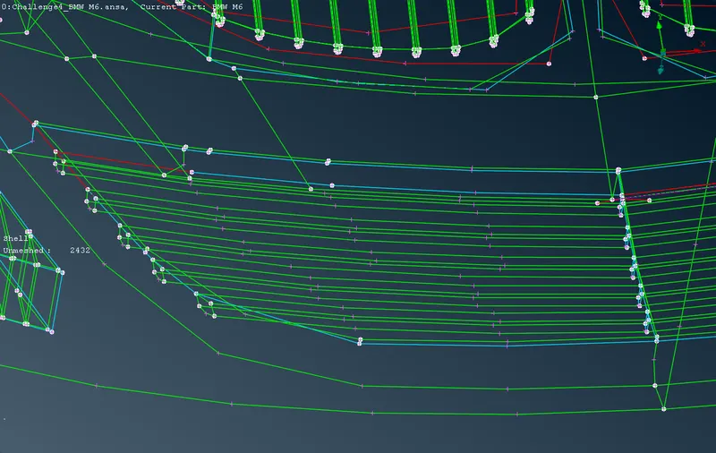
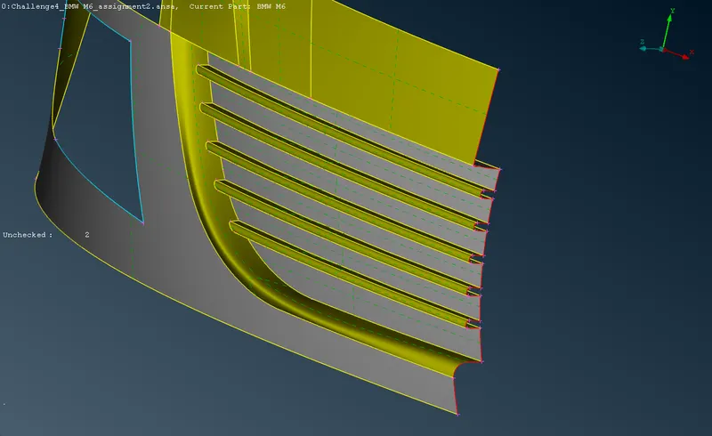
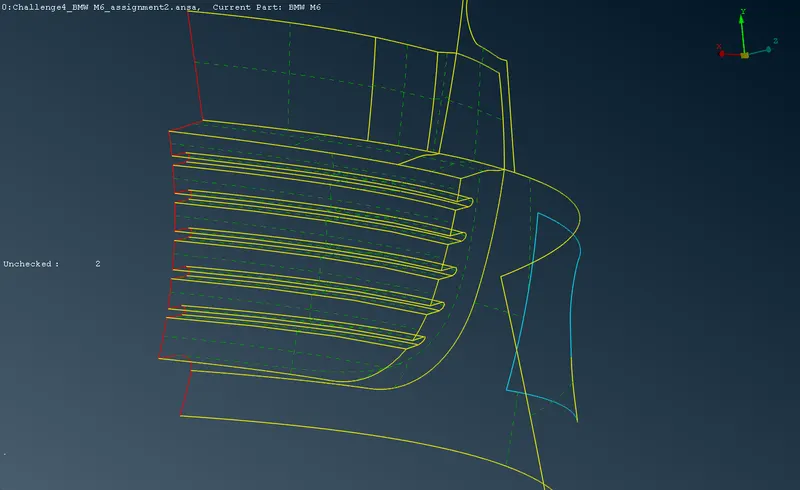
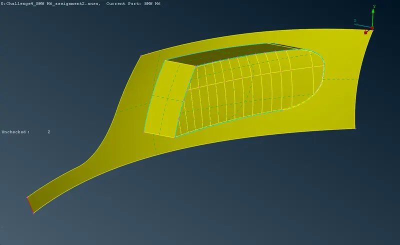
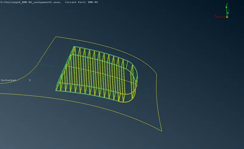
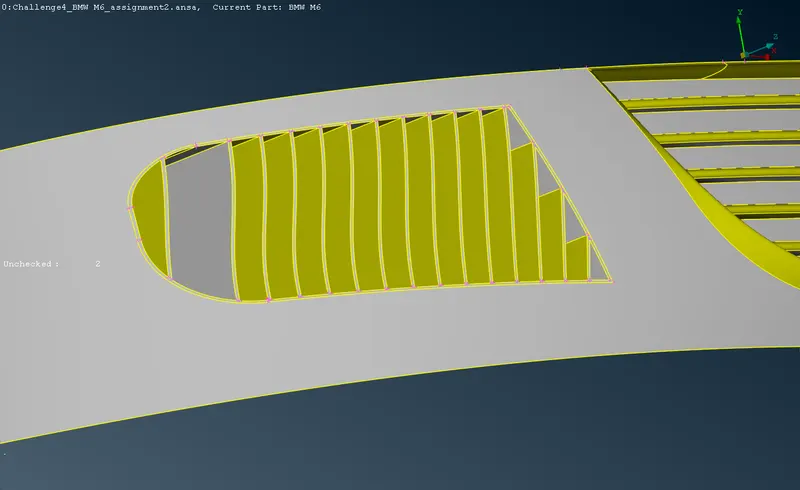
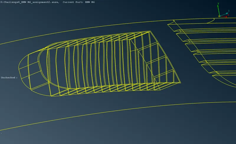
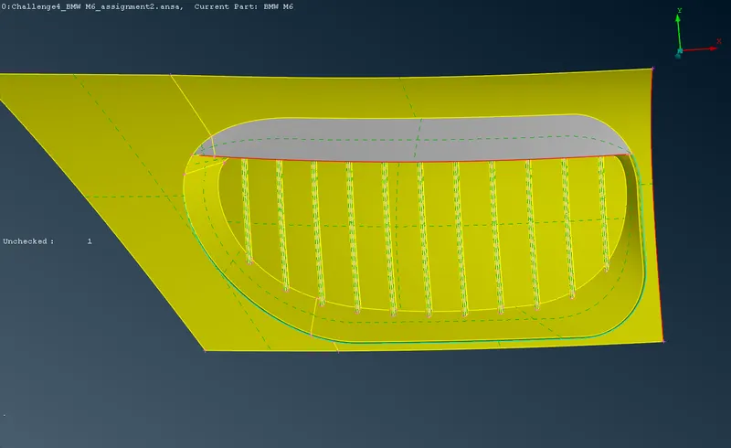
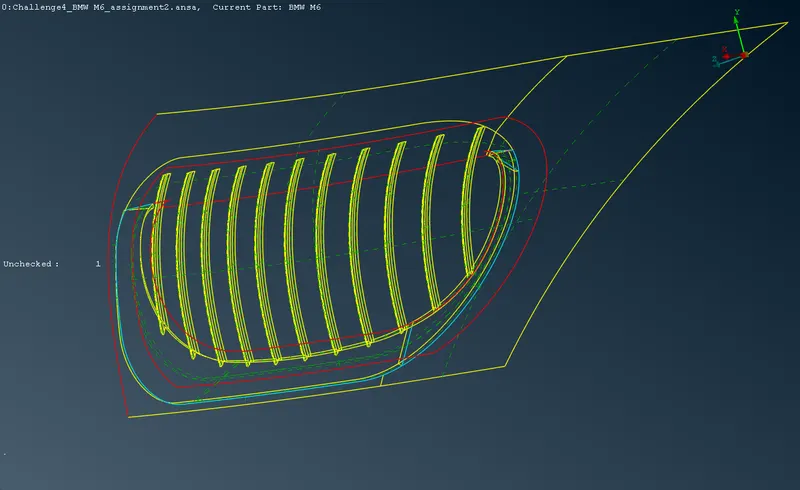
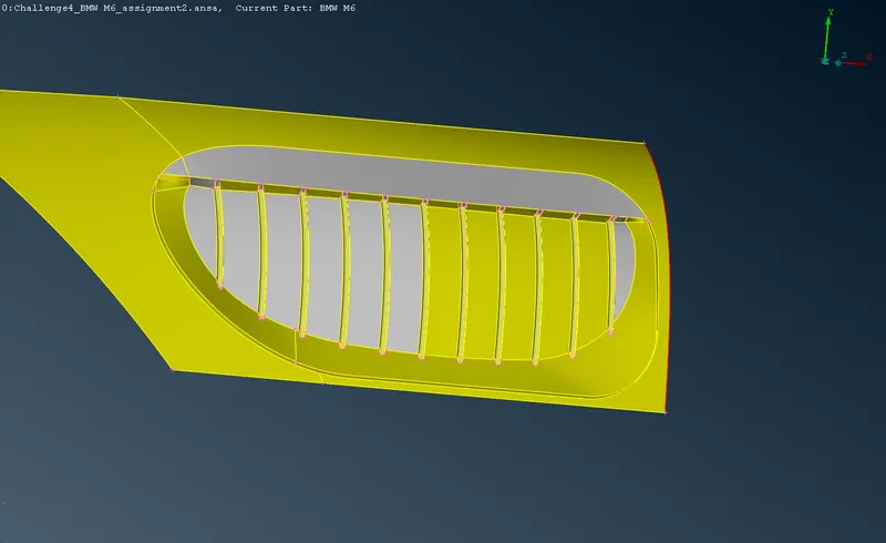
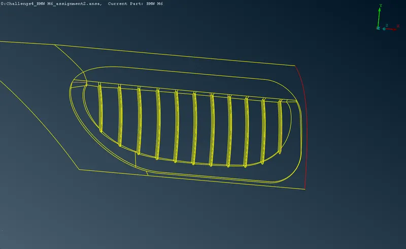
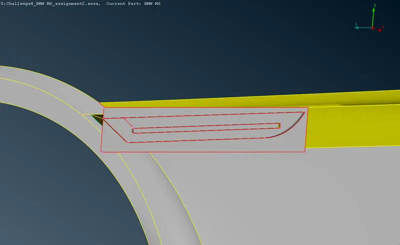
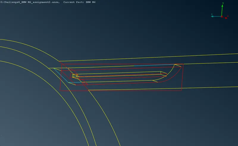
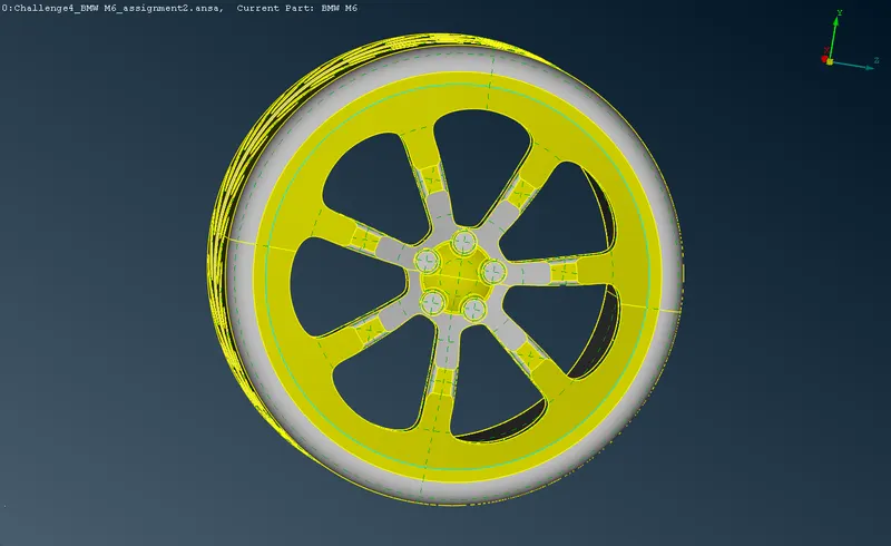
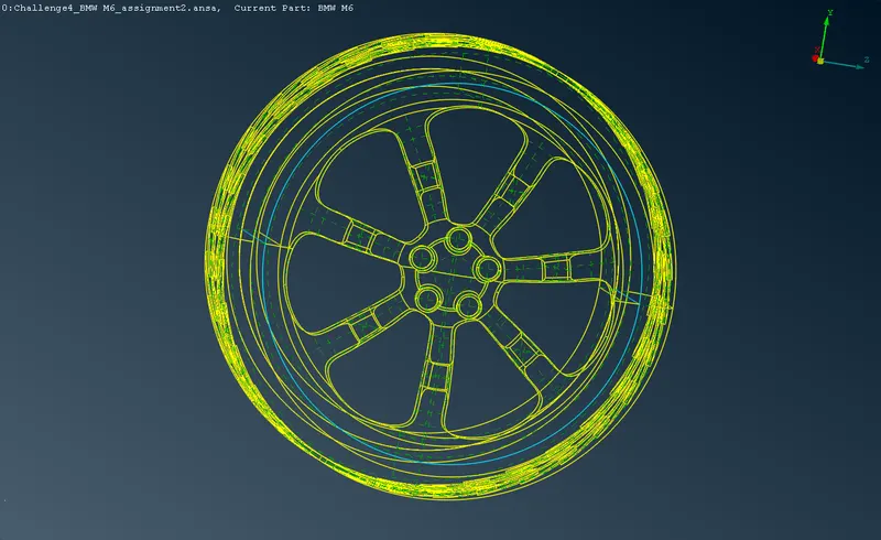
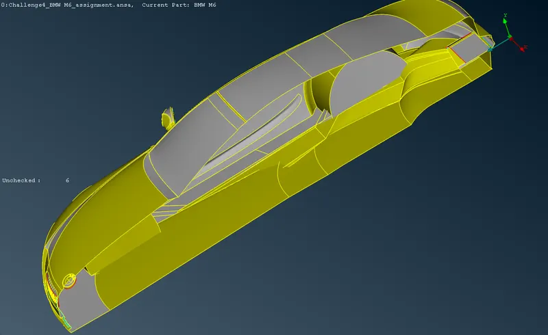

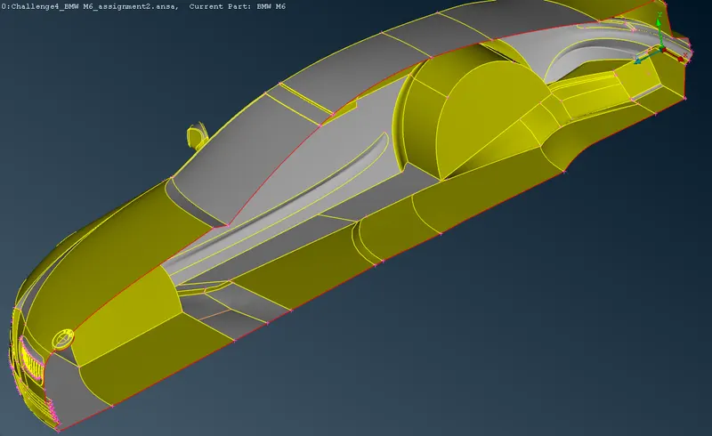
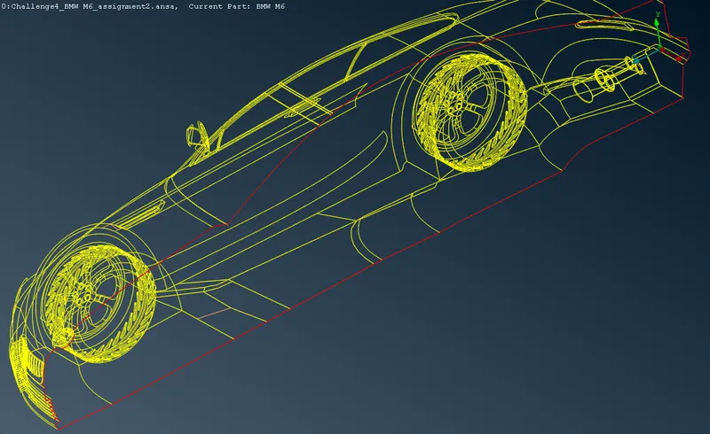
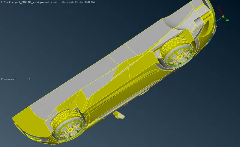
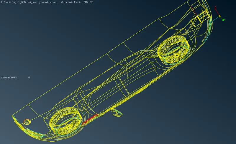
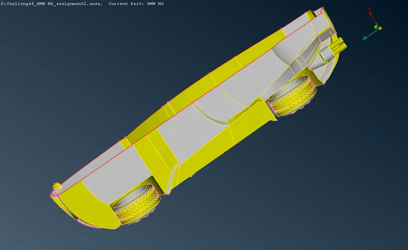
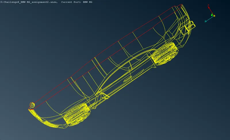
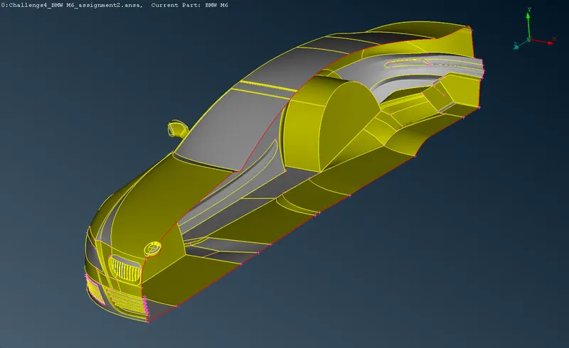
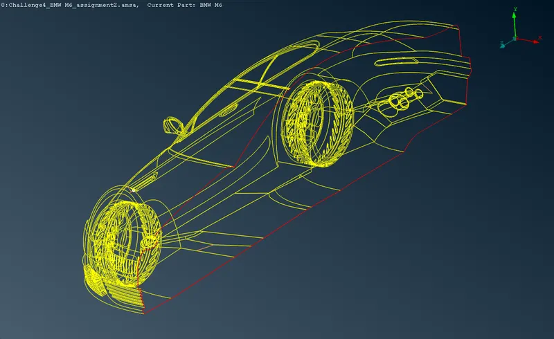
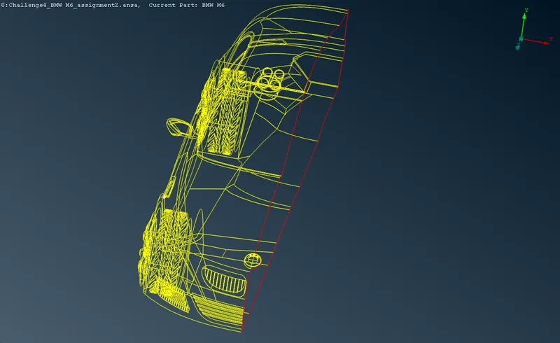
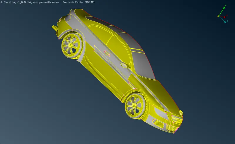
After the cleanup, it can be seen that the red-colored single cons are present only at the corners which form the cutting plane of symmetry. All the other surfaces should be free from single cons and also triple cons, as triple cons ought to form a separate volume which should be avoided.
3.3 Geometry check and rectification:
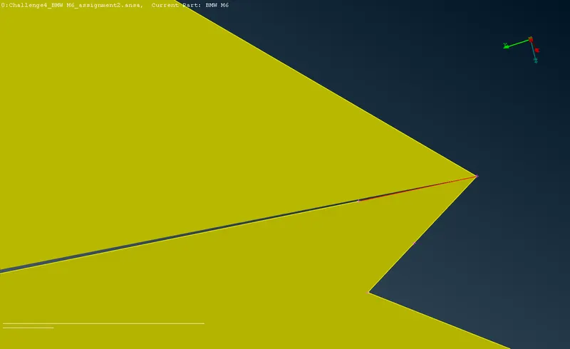
After the cleanup is done with a manual inspection, the geometry is inspected with the checks manager provided by ANSA. This rectifies all the remaining errors and gives a 100% error free geometry.
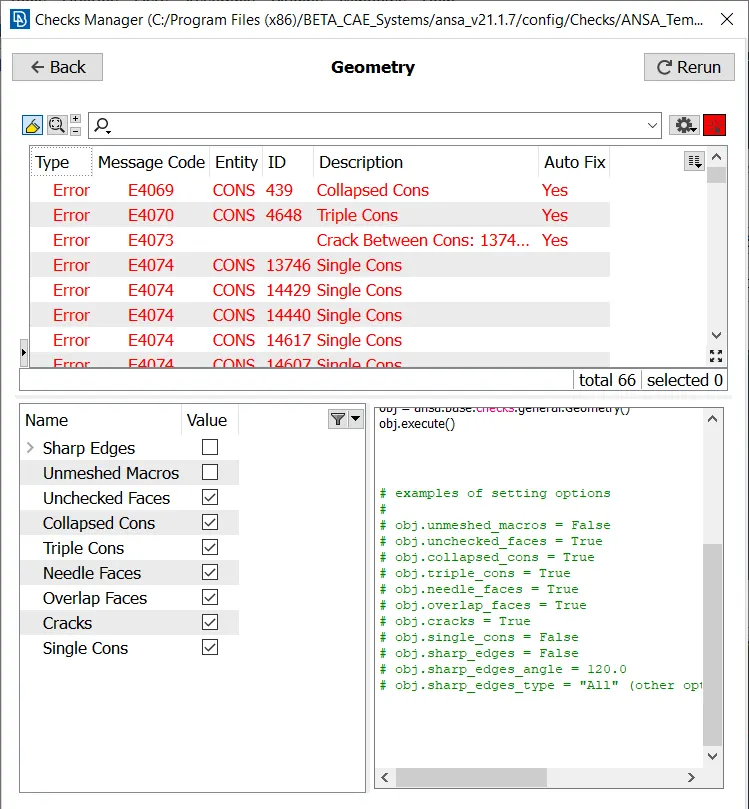
The single cons identified are examined carefully and is verified that they should belong to the cutting plane. All the other single cons present elsewhere are rectified along with the triple cons and collapsed cons.
| Before optimization | Tools and methods | After optimization |
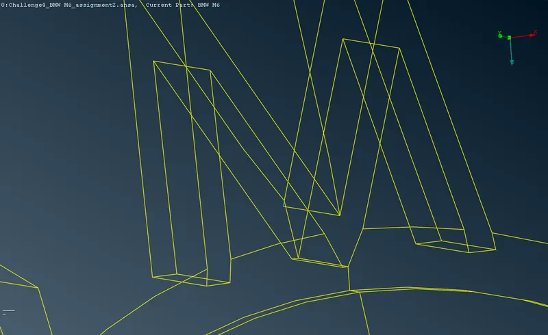 |
A triple con present at the interface is removed using 'Topo' tool. | 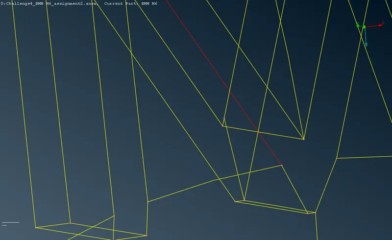 |
 |
Two single cons with a gap in between is solved using the 'Paste' tool | 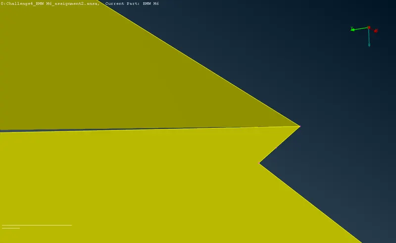 |
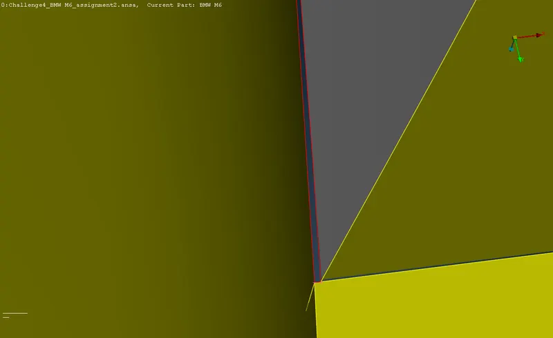 |
Two single cons with a gap in between is solved using the 'Paste' tool | 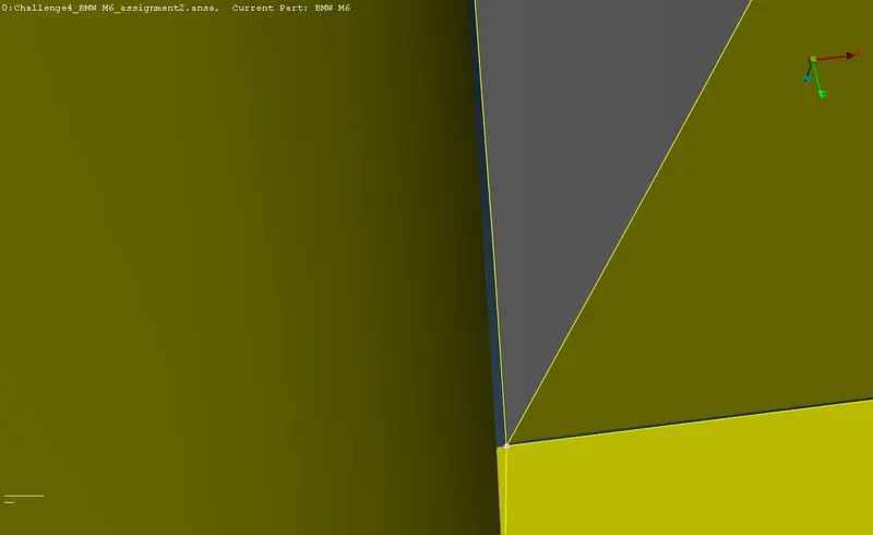 |
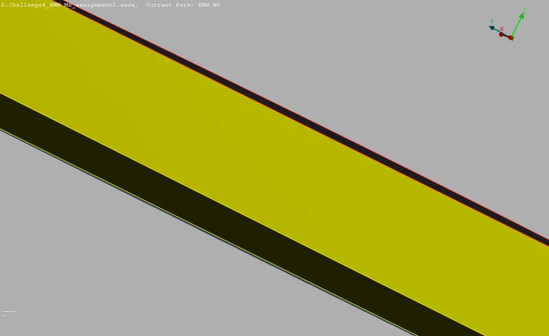 |
Two single cons with a gap in between is solved using the 'Paste' tool | 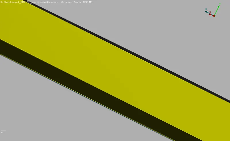 |
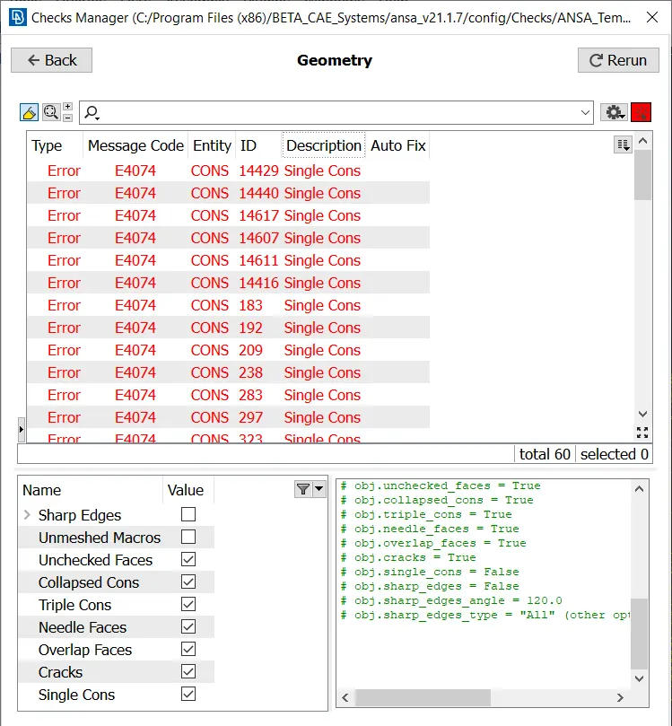
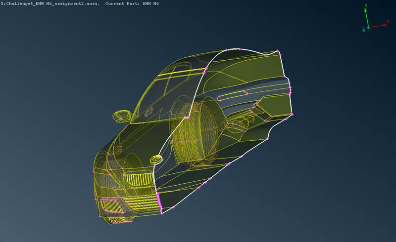
After resolving all the anomalies, the geometry is a perfect model with a cutting plane; which can be taken to surface meshing. It is verified by a final geometry check after resolving.
3.4 Assigning PIDs:
PIDS are assigned to individually define the parts of the model based on the purpose of giving unique element size in meshing. In this model, various PIDs include The BMW hood ornament, The exhaust, The front and rear lights. the front grills, The rear view mirror, The wind shield, The rims and tyres and the body skin.
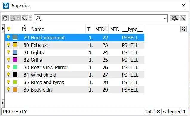
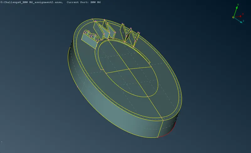
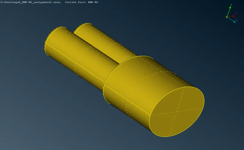
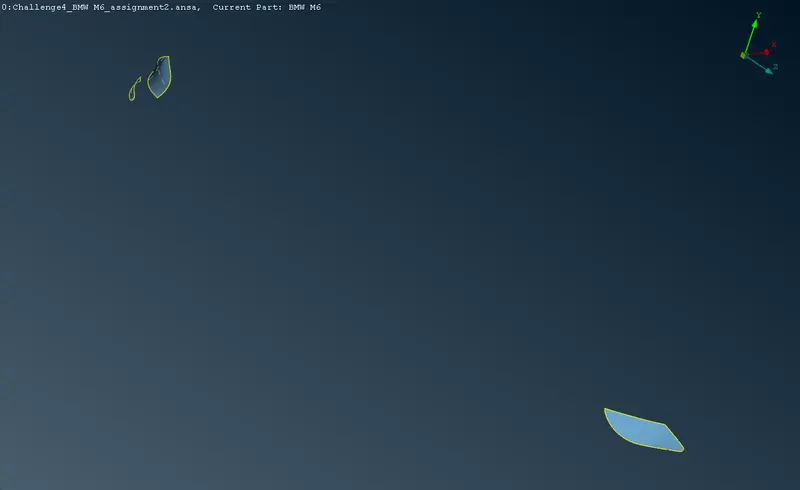
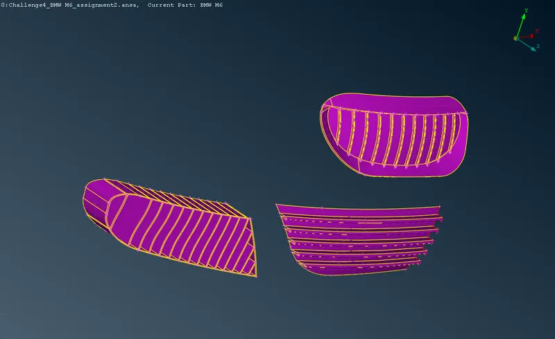
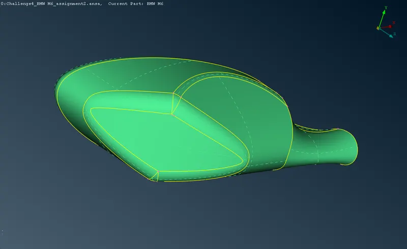
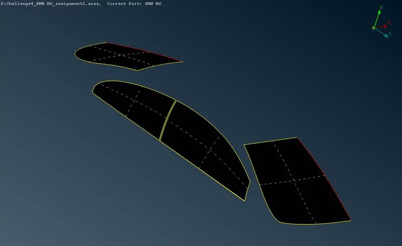
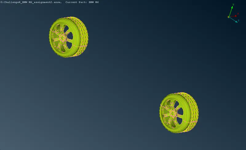
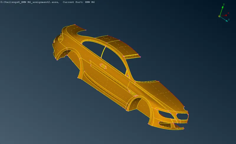
Each PID and its interface with the other adjoining PID is identified by the color coding given in the PID manager.
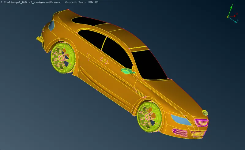
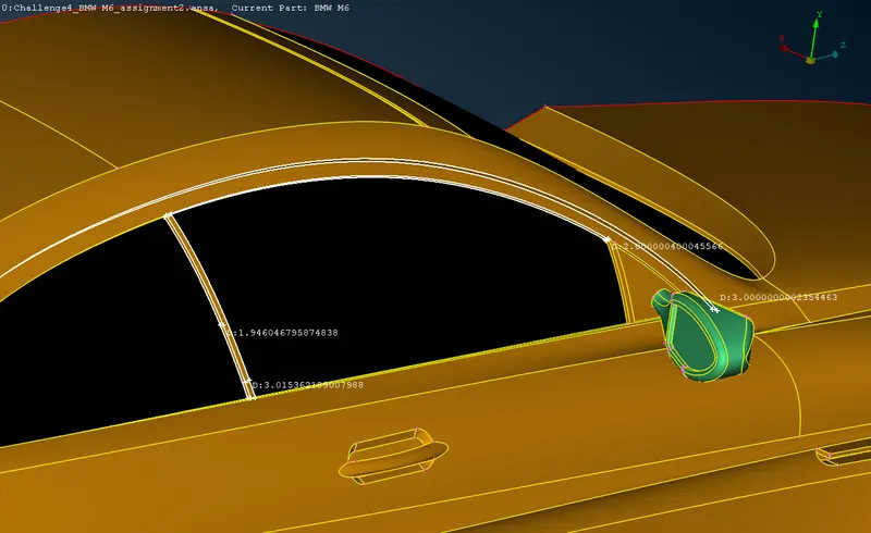
3.5 Entities measurement:
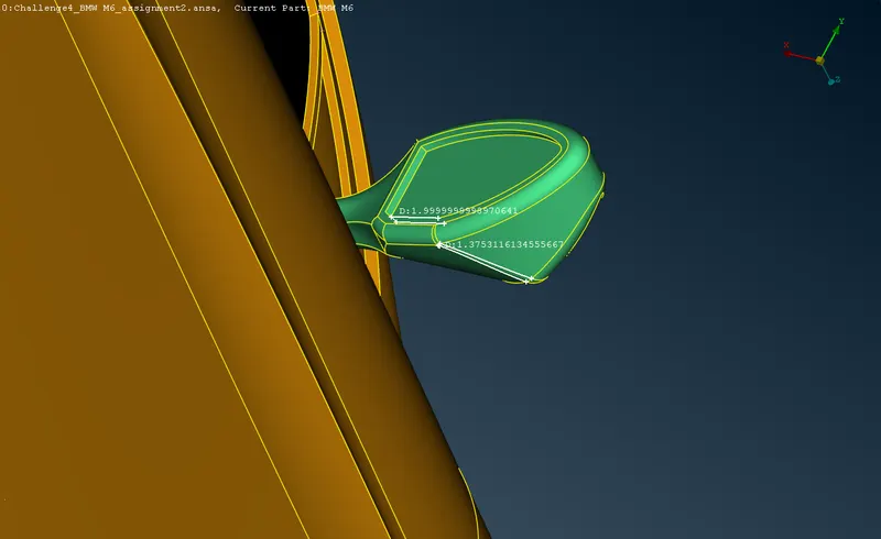
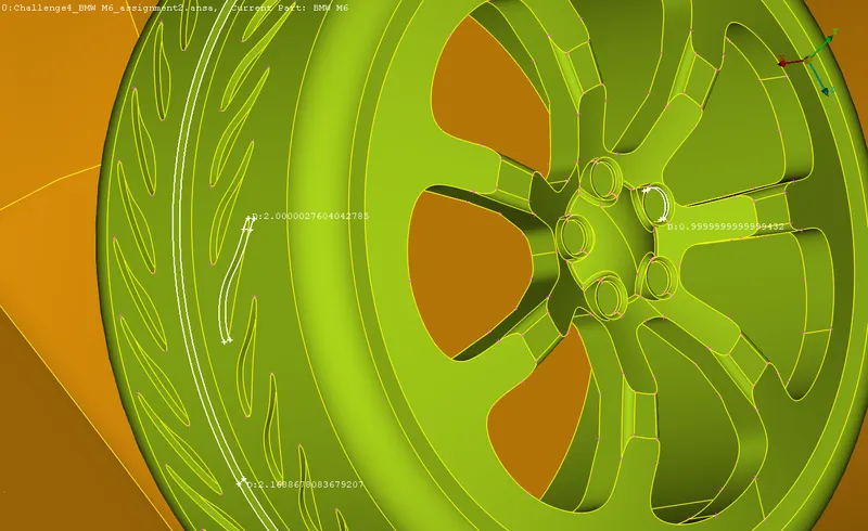
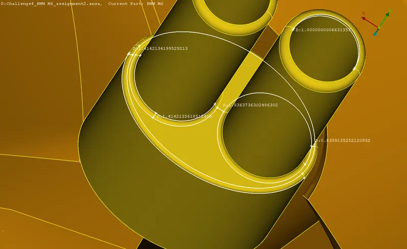
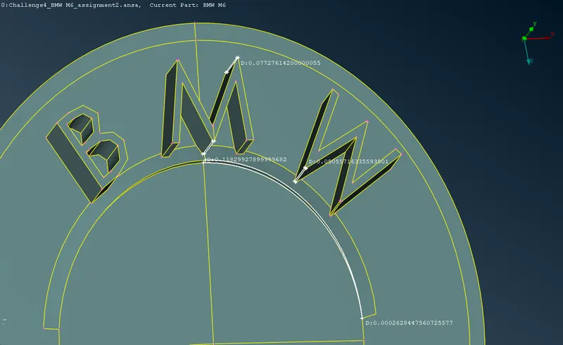
Smallest surfaces in the entities are measured to determine the minimum and maximum length parameters for the surface mesh. These measurements are referred to fix the quality criteria. For an optimized mesh the smallest surfaces are avoided up to an extent. Some features of the entities cannot be avoided and hence used as the min and max quality criteria.

3.6 Quality check and optimization:
3.6.1 Surface optimization:
Before surface meshing is done, the surfaces are inspected manually to qualify the quality criteria and optimization is also done to eliminate those surfaces. Measured entities are used as reference to identify the small surfaces and optimize them.
| Before optimization | Tools and methods | After optimization |
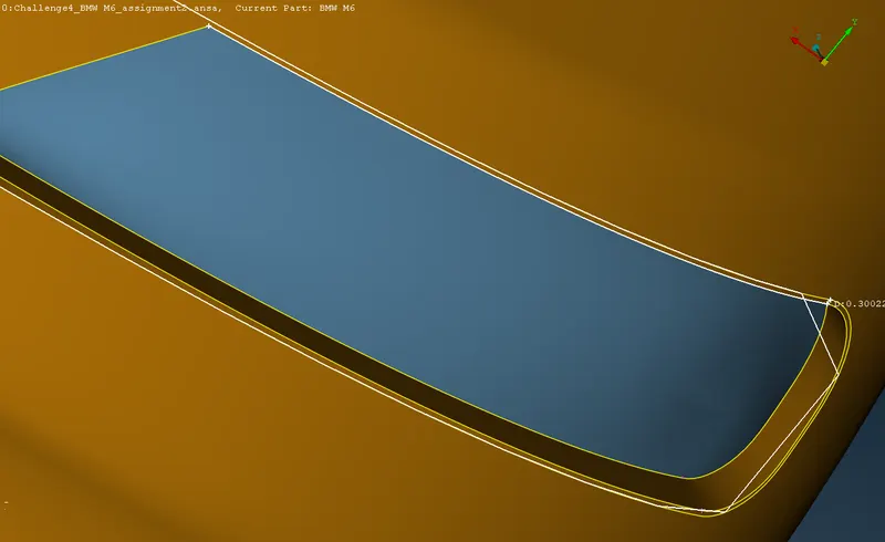 |
There are two layer of double cons present outer to the rear lights, which is made into one layer of double cons to eliminate the small cross sectional surface. | 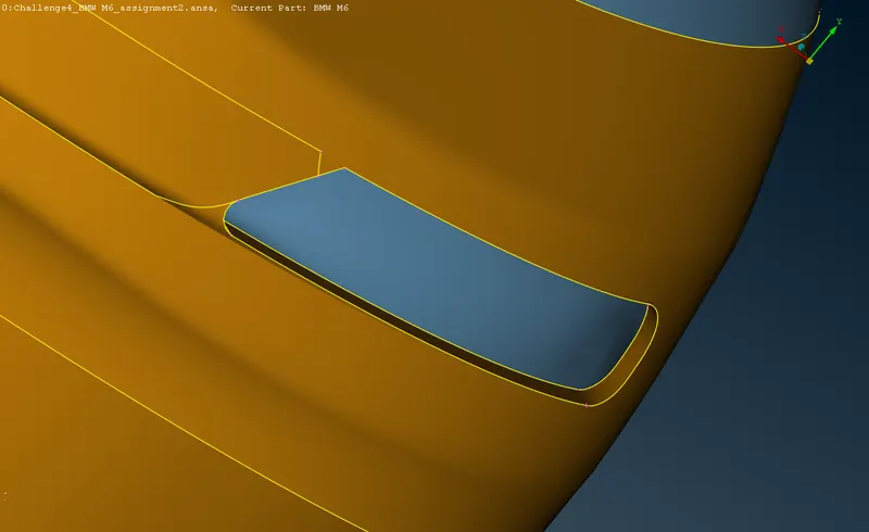 |
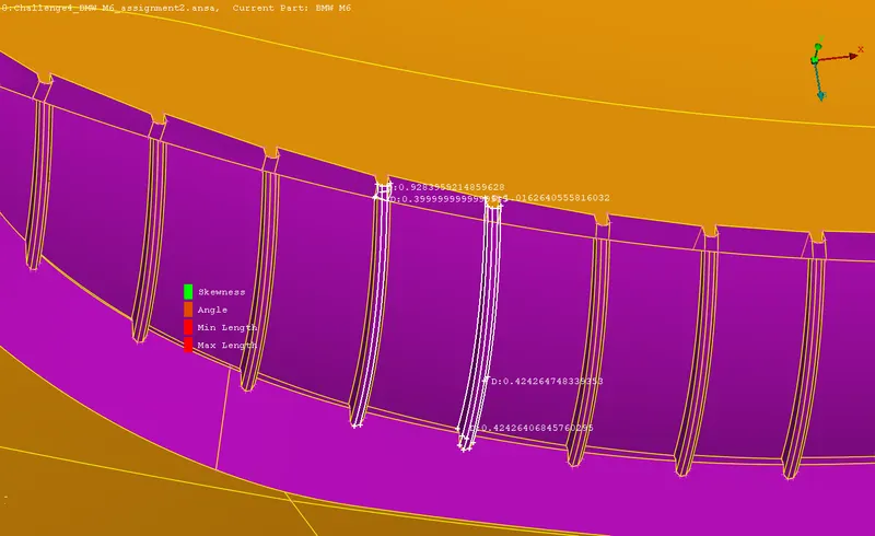 |
The unwanted cons are cut and the hot points are removed which resulted in a single surface on the top side, eliminating small surfaces. | 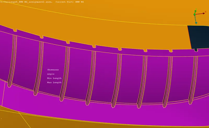 |
|
The small quadrant is eliminated while the bottom small surface of M and W is converted into a single surface fusing with the slant surface. | 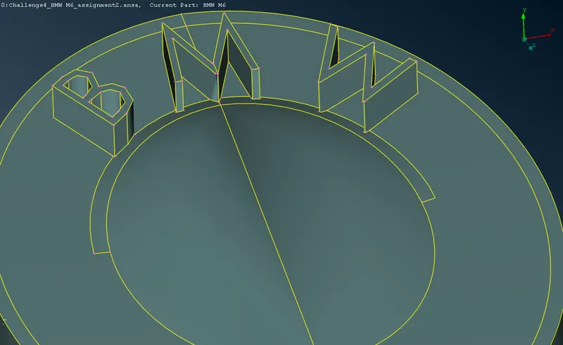 |
|
|
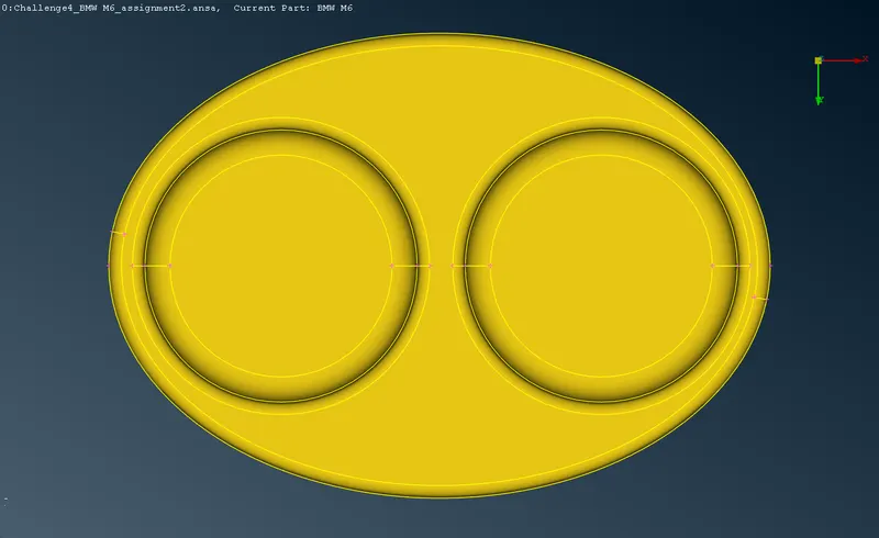
The cuts which are required to maintain the fillets are shifted from the areas of corner proximity and placed elsewhere around the exhaust outlet. | 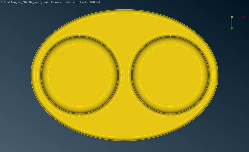 |
3.6.2 Mesh optimization:
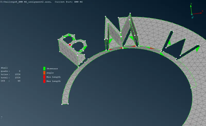
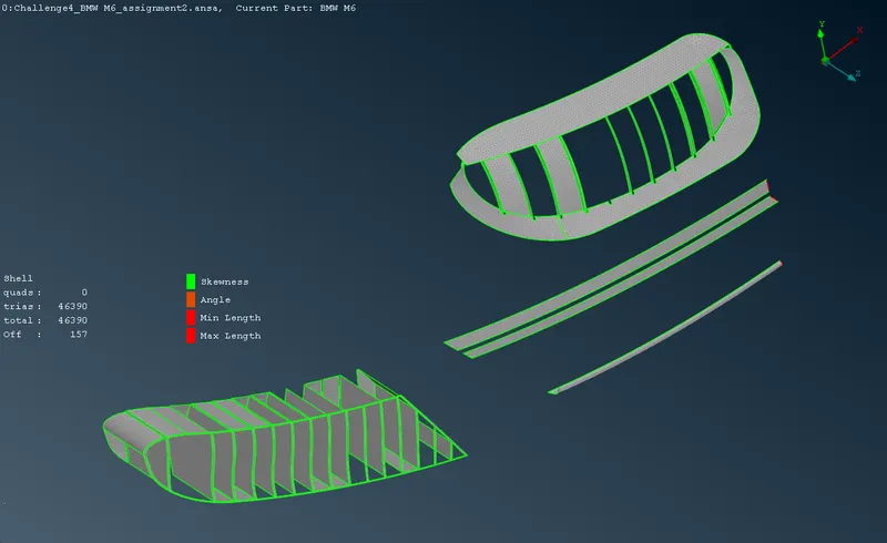
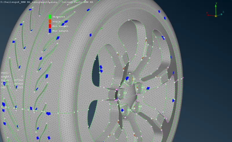
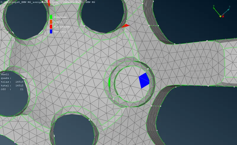
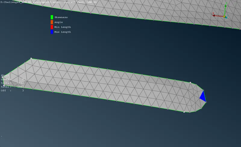
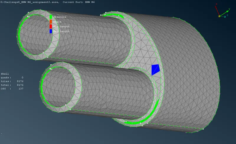
The off elements in the surface mesh have to be optimized to satisfy the quality criteria. Shell mesh > Reconstruct, Shell mesh > Improve, Shell mesh > Smooth tool is used to automatically optimize some of the off elements. The remaining off elements have to be optimized manually by using the mesh improvement tools. The various defects in the mesh is identified with the visual color palette. Tools like Grids > Move, Grids > Paste, Grids > Origin, Grids > Align in the Grids group and Elements > Swap, Elements > Split, Elements > Stitch, Elements > Join in the shell mesh group from the Topo menu is used for mesh improvements.
3.7 Surface mesh:
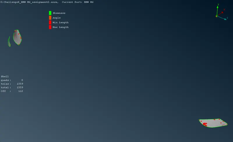
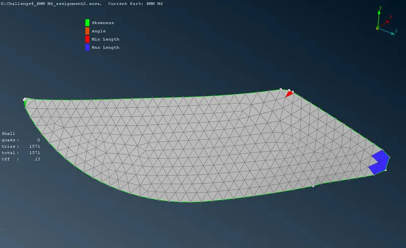
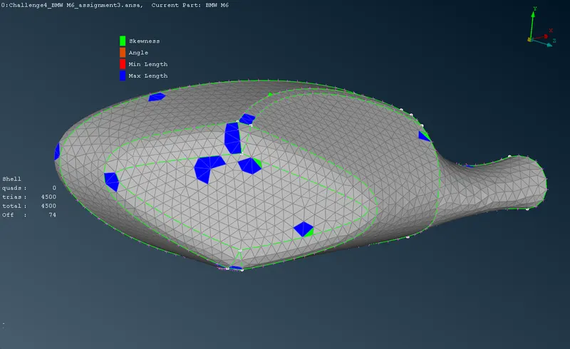
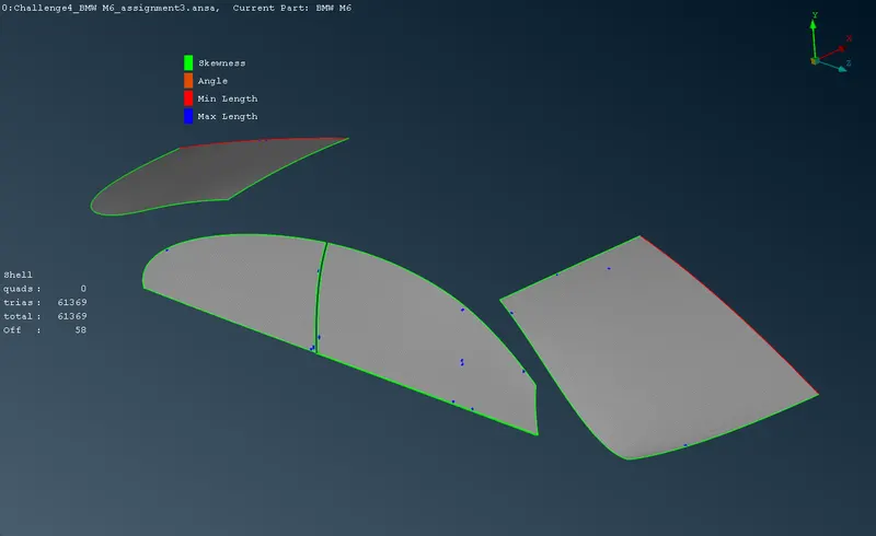
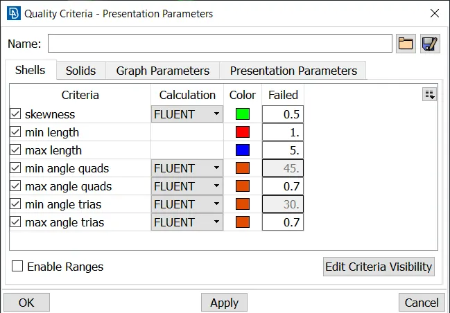
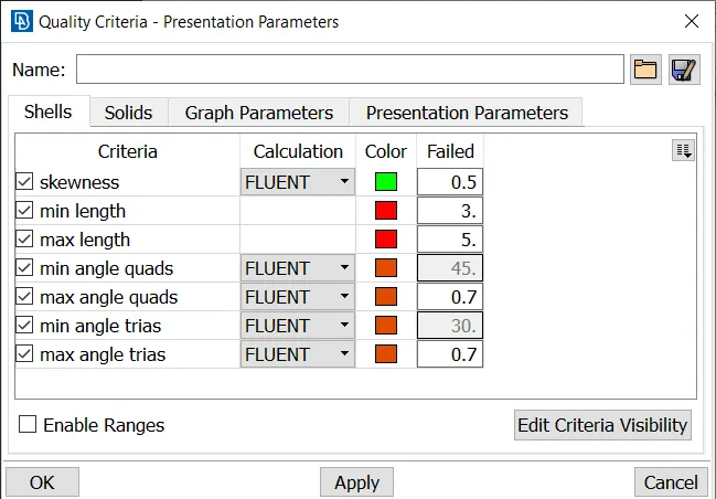
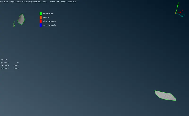
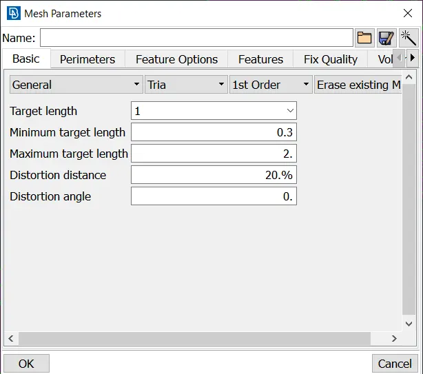
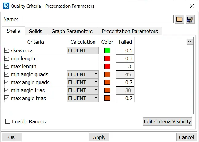
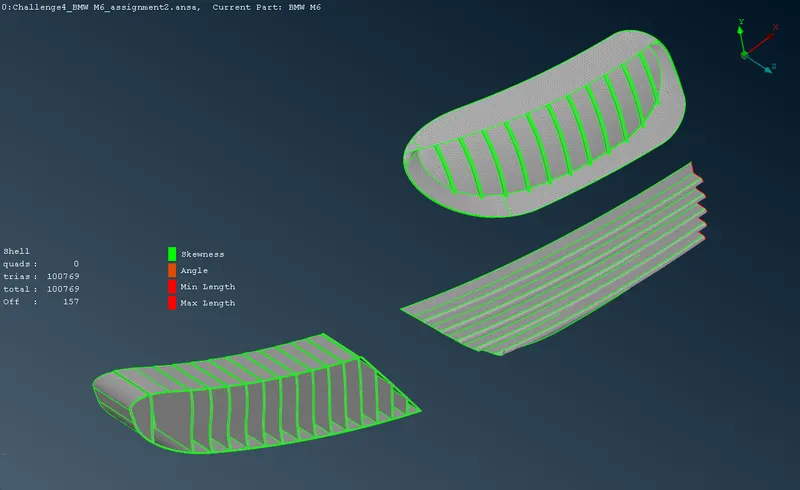
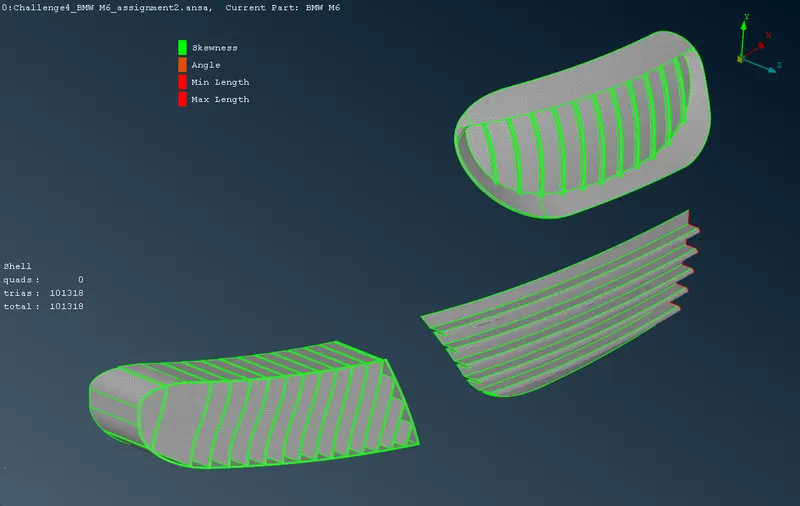
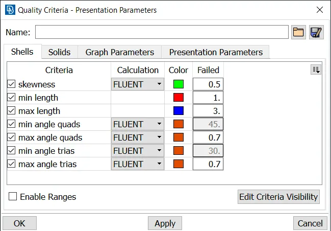
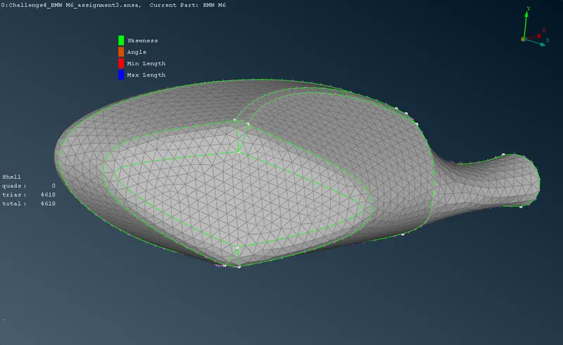
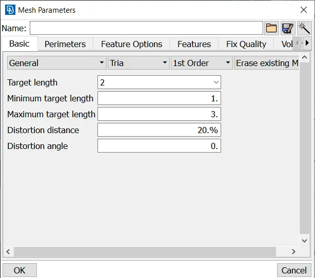
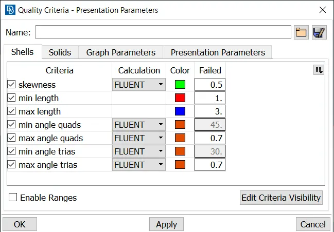
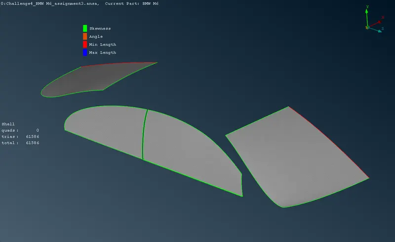
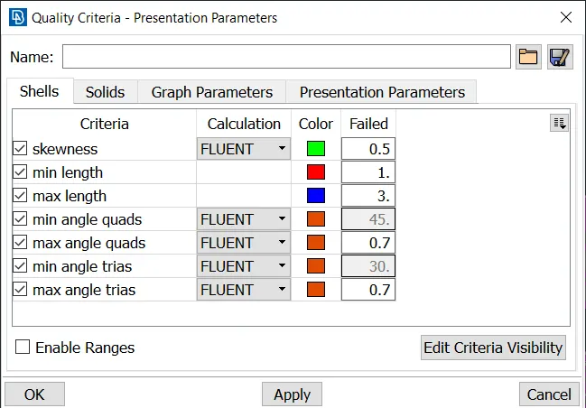
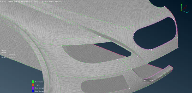
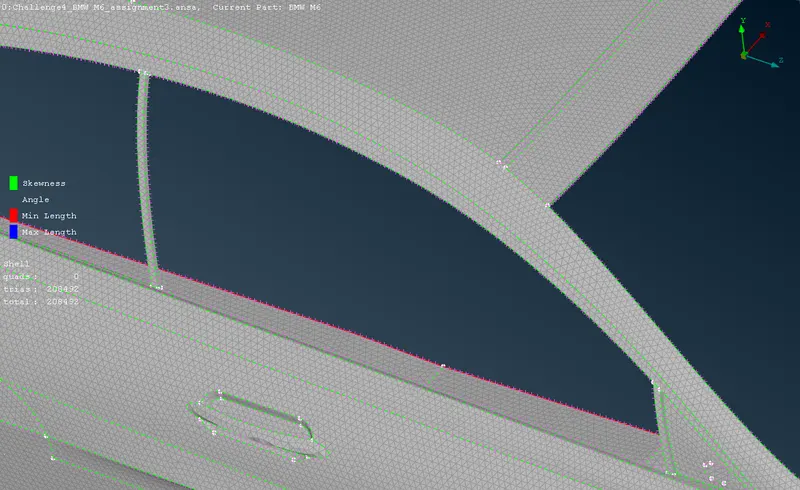
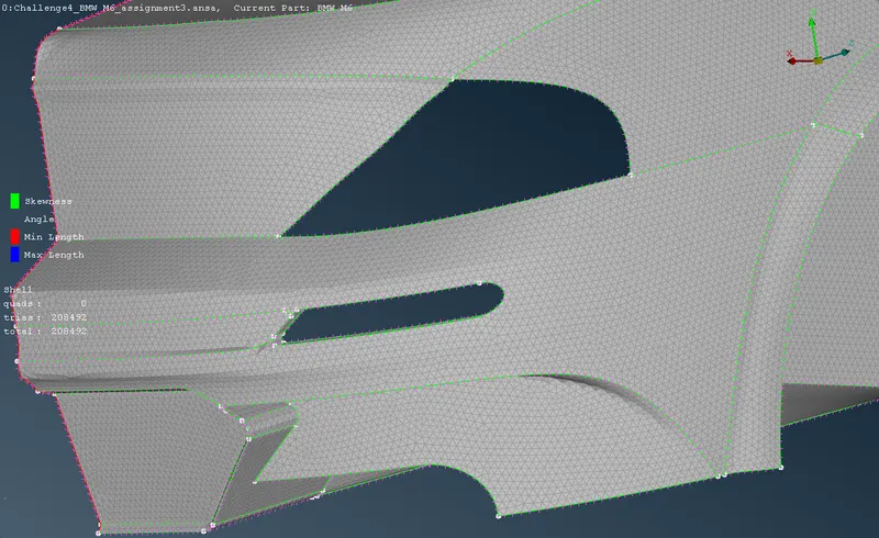
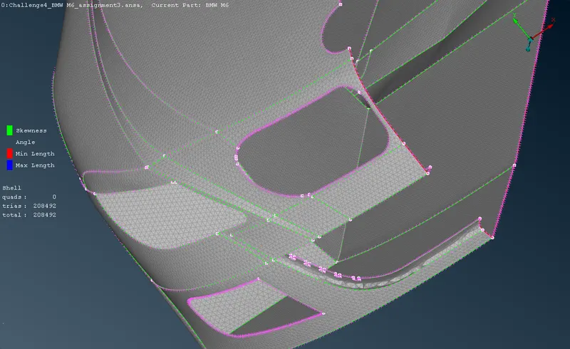
Surface meshing is done to individual PIDs with different sizes to satisfy the quality criteria. The quality criteria include skewness, max and min length with max and min angle trias.
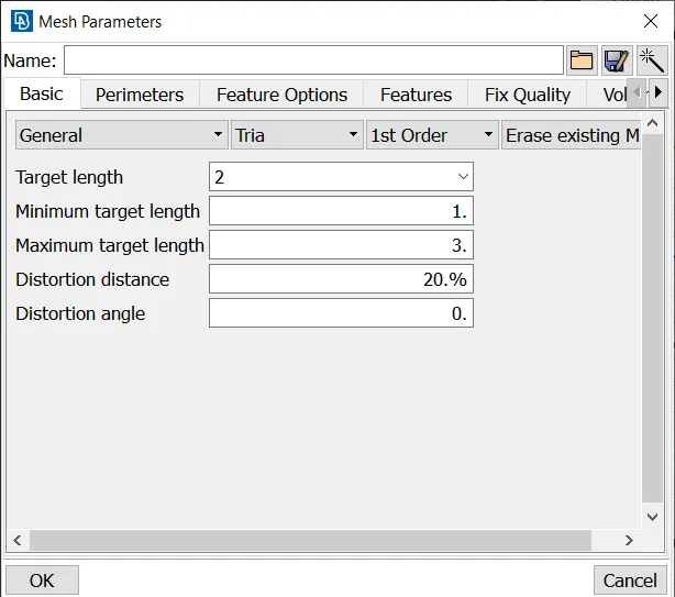
'Perimeter > Length' and 'Macro > Length' is used to define the meshing length of the surfaces.
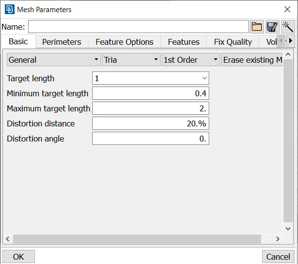
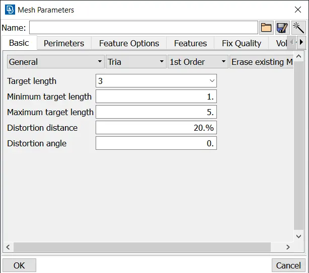
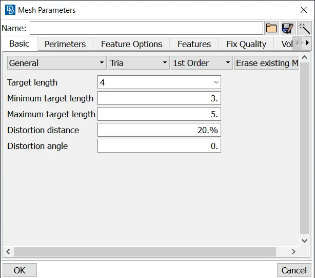
'Tria' mode with sufficient max and min size based on the measurements is defined to the PIDs.
The min and max length depends on the smallest and biggest surface present in the PIDs which cannot be avoided in the topology correction stage.
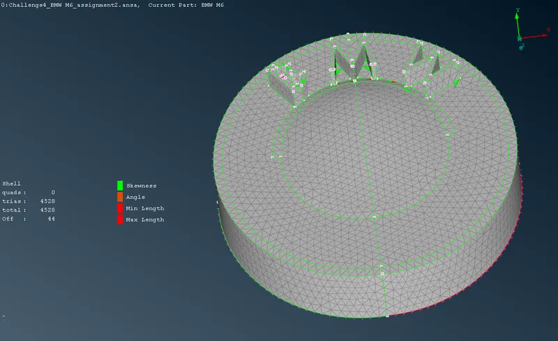
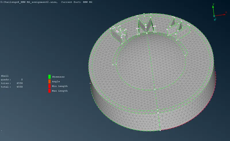
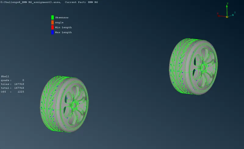
The off elements which failed to satisfy the quality criteria are identified using the color pattern and resolved with mesh improvement tools, which are briefly defined above.
3.7.1 PID 1 - Hood Ornament:
|
Mesh parameters: |
Quality criteria: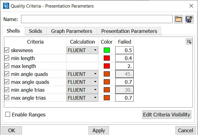 |
|
Base mesh: |
Quality mesh: |
3.7.2 PID 2 - Exhaust:
|
Mesh parameters:
|
Quality criteria:
|
|
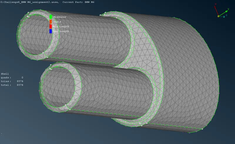
Base mesh:
|
Quality mesh:
|
3.7.3 PID 3 - Lights:
|
Mesh parameters:
|
Quality criteria:
|
|
Base mesh:
|
Quality mesh:
|
3.7.4 PID 4 - Grills:
|
Mesh parameters:
|
Quality criteria:
|
|
Base mesh:
|
Quality mesh:
|
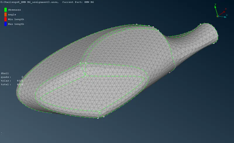
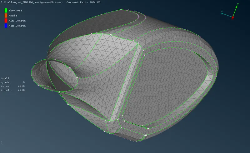
3.7.5 PID 5 - Rear view mirror:
|
Mesh parameters:
|
Quality criteria:
|
|
Base mesh:
|
Quality mesh:
|
3.7.6 PID 6 - Windshield:
|
Mesh parameters:
|
Quality criteria:
|
|
Base mesh: |
Quality mesh: |
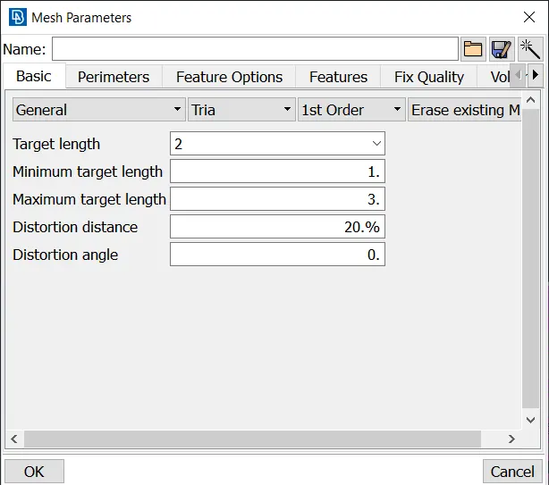
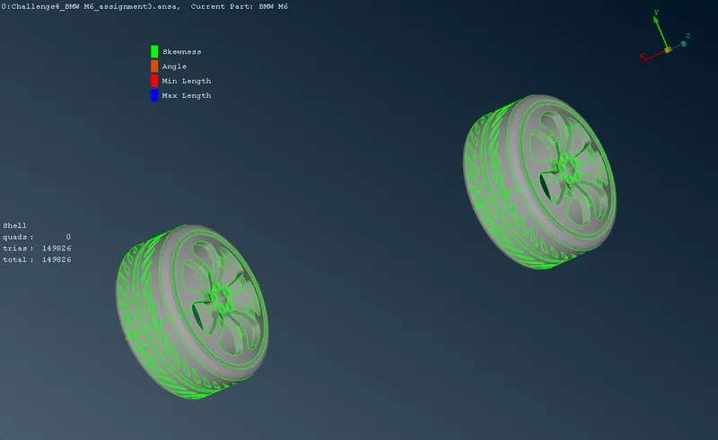
3.7.7 PID 7 - Rims and Tyres:
|
Mesh parameters:
|
Quality criteria:
|
|
Base mesh:
|
Quality mesh:
|
3.7.8 PID 8 - Body skin:
|
Mesh parameters:
|
Quality criteria:
|
|
Base mesh:
|
Quality mesh:
|
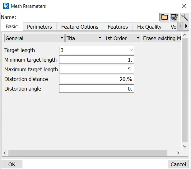
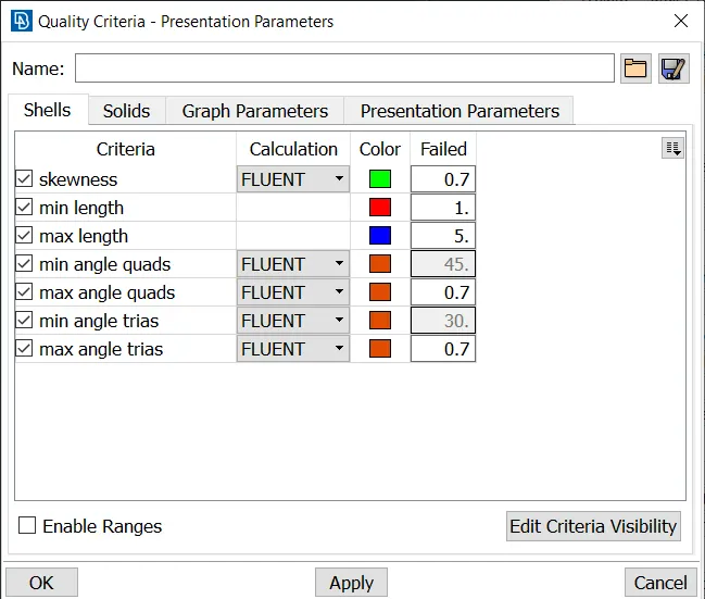
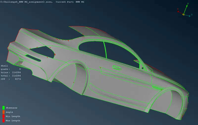
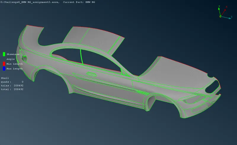
All the PIDs are successfully meshed and is in accordance with the quality criteria after mesh improvement.
3.8 Geometry duplication:
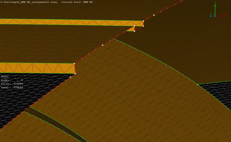
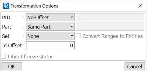
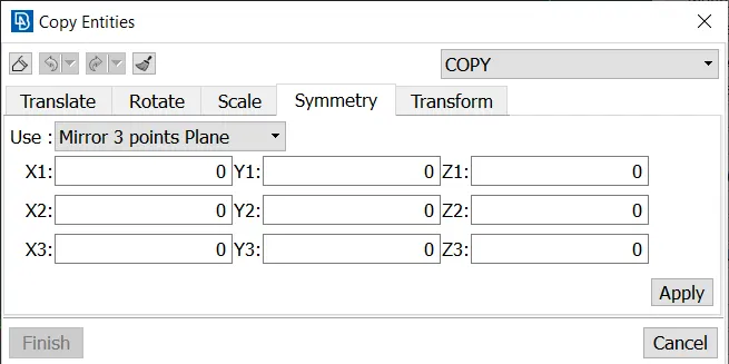
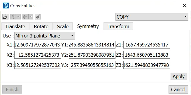
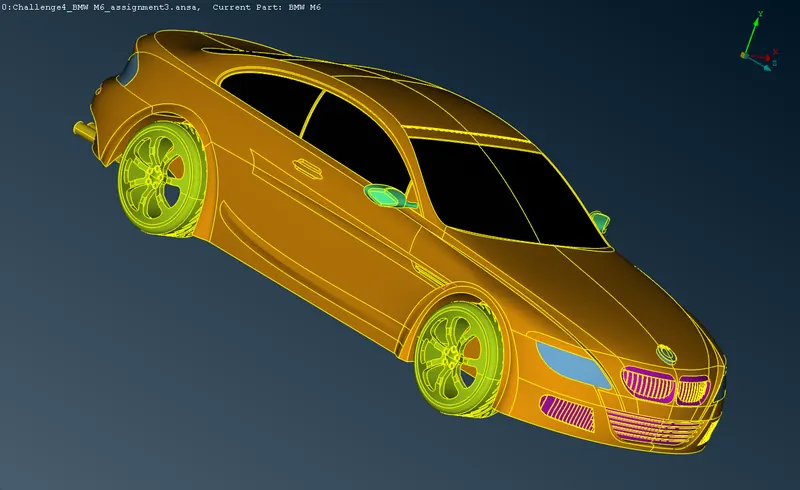
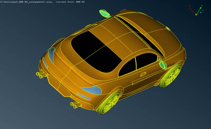
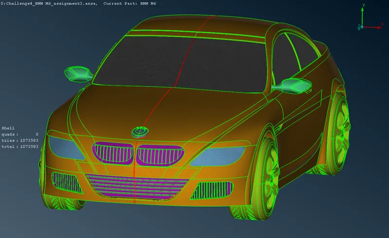
After surface meshing and the quality criteria for all the PIDs have been justified, the model is duplicated symmetrically on the YZ plane with the same PIDs and shell mesh.
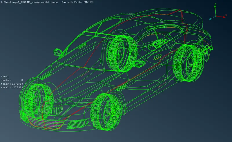
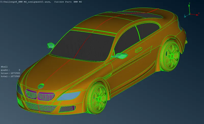
3.9 Wind tunnel designing:
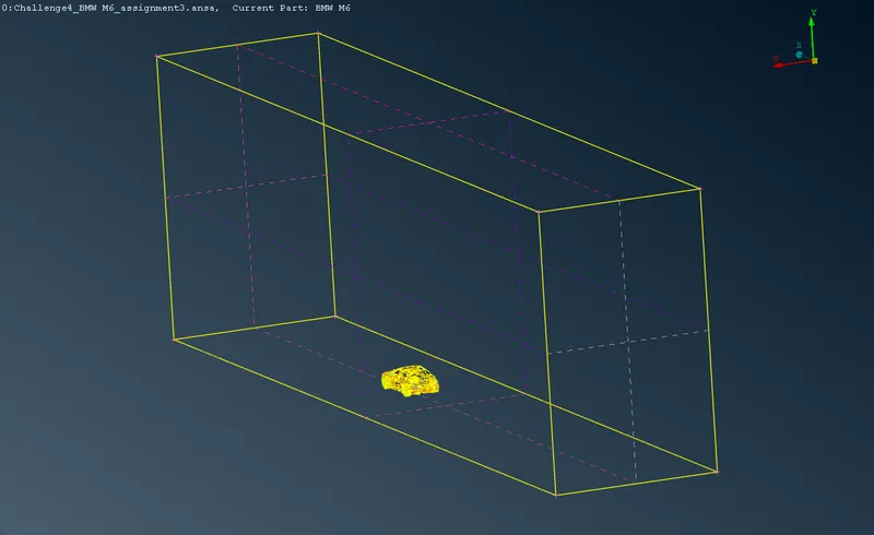
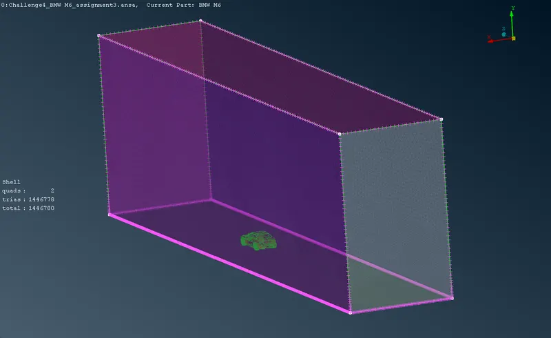
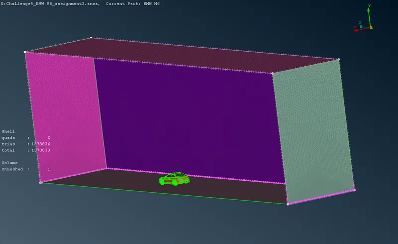
The measures are taken on the car body to determine the wind tunnel size. A typical wind tunnel has 4x distance in the front, 6x distance in the back, 3x distance in the top and x distance on both the sides, with a minimal distance in the bottom.
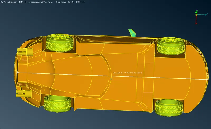
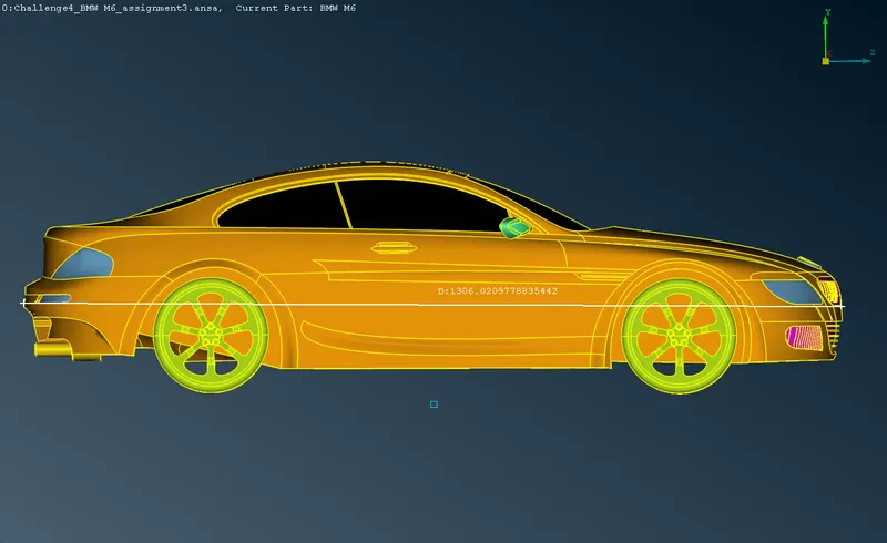
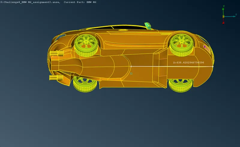
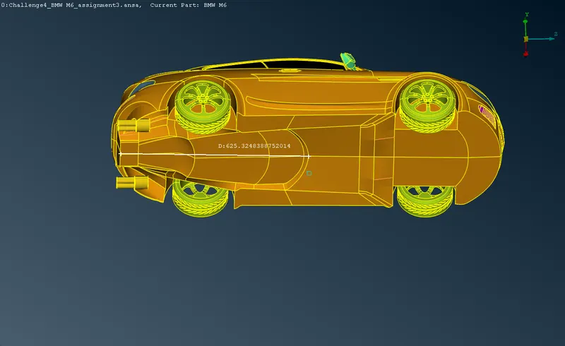
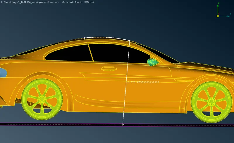
To build the wind tunnel, a single point is defined at 75mm (-y) from the lowest point of the car, using Points > Create tool. Another point at 5800mm (+z), 8425mm (-z) , 1300 (+x), 1300 (-x) are defined which makes the base surface of the tunnel; based on the measurements. The base surface is offset to create the roof of the tunnel using Faces > Offset tool. The walls on the 4 sides are defined as the new surface coons using Faces > New > Fitted.

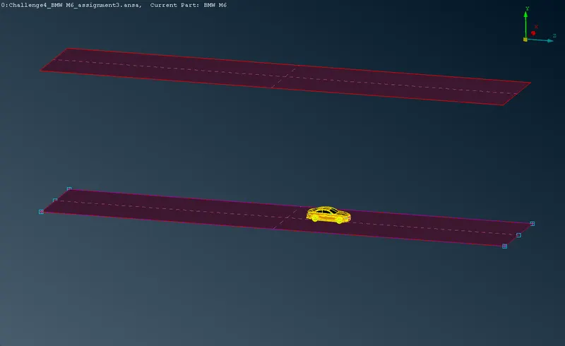
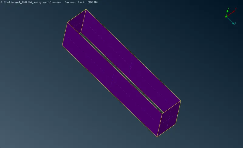
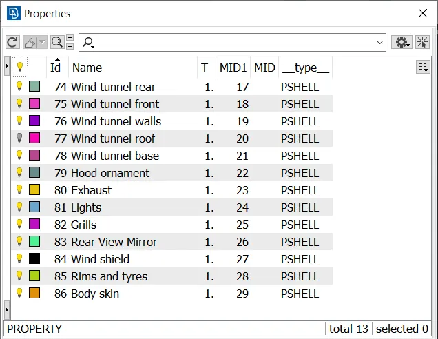
The PIDs are defined as per the convenience of the meshing application. The side walls are given as separate PID. The roof and the base are given as separate PIDs.
3.10 Wind tunnel surface mesh:
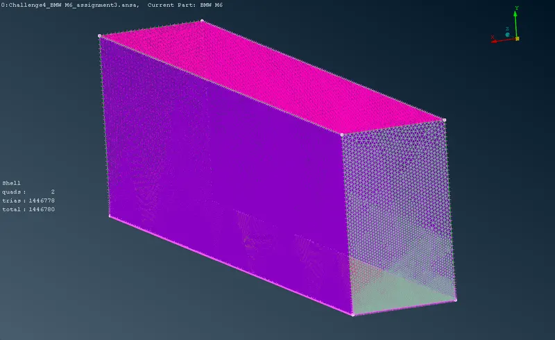
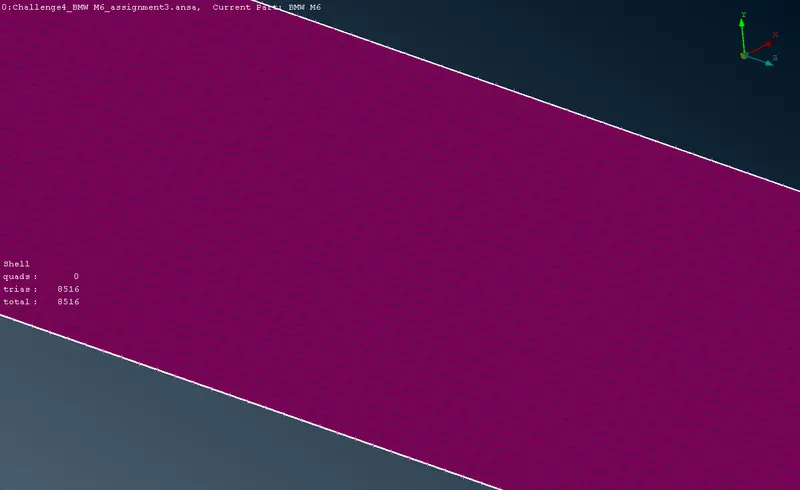
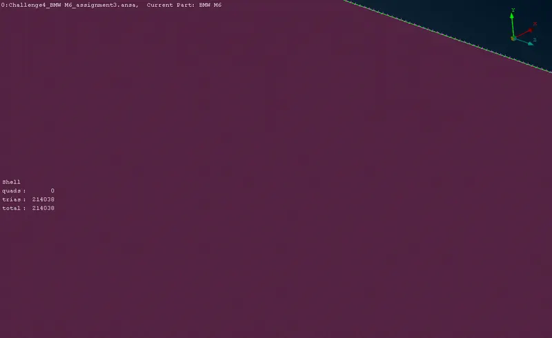
The roof and base of the tunnel are meshed with a uniform mesh size of 100mm and 20mm respectively with tria elements. The perimeter and macro lengths are also defined as 100mm and 20mm respectively.
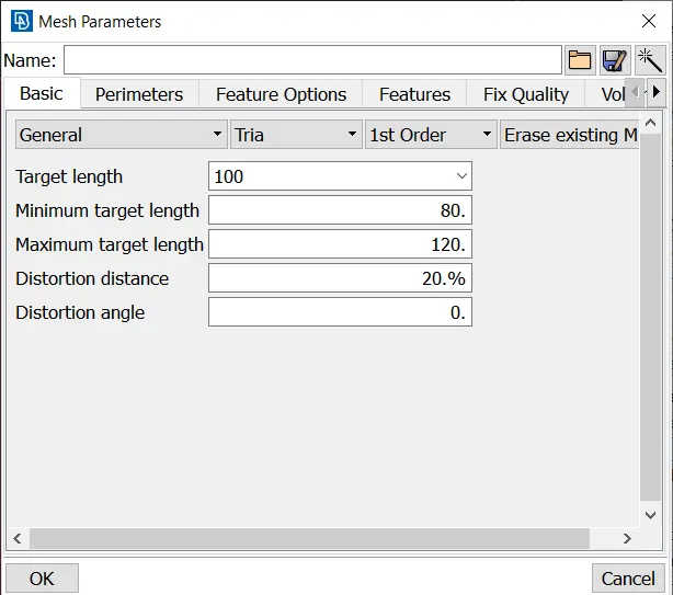
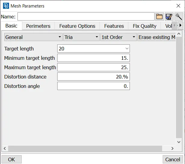
The side walls perimeter is defined using the perimeter > Spacing tool to provide a linear varying perimeter from 20mm to 100mm by a factor of 1.1.
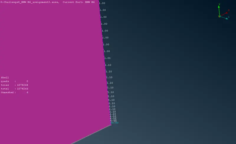
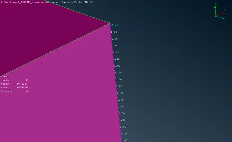
The side walls are meshed individually using Mesh Generation > Spot Mesh tool as the lengths are already defined.
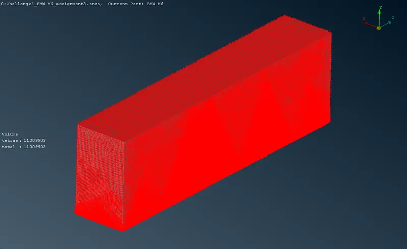
3.11 Volumetric meshing:
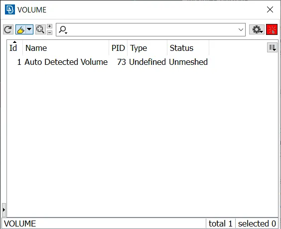
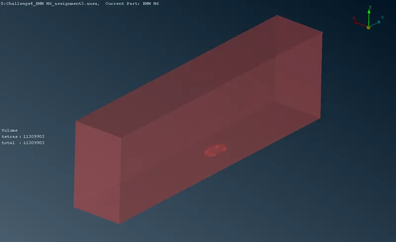
Volumes > Define > Auto define is used to define the volumes present in the whole database. 8 volumes has been detected automatically by ANSA in which the volumes other than the volume between the tunnel and the car body has to be removed, which is not an area of concern.
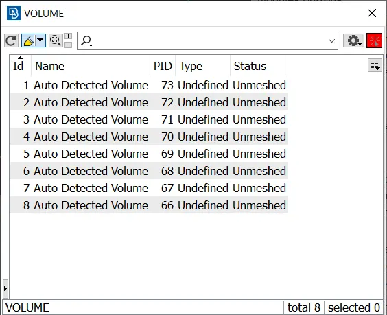
The below-mentioned volumes are deleted as they are not involved in the study.
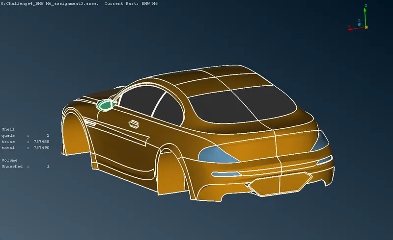
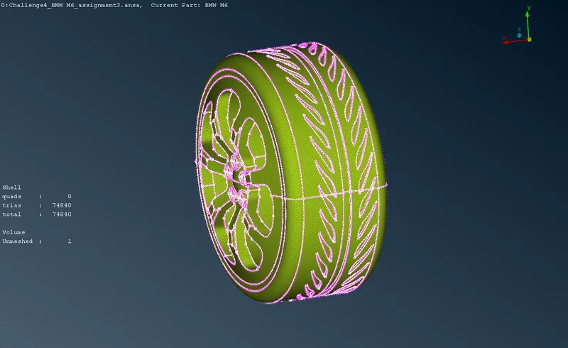
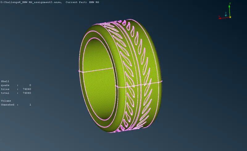
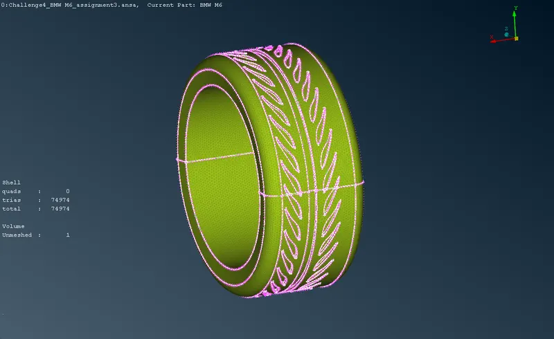
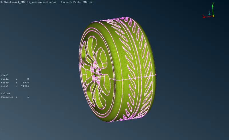
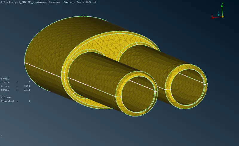
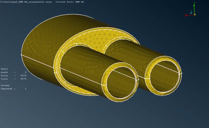
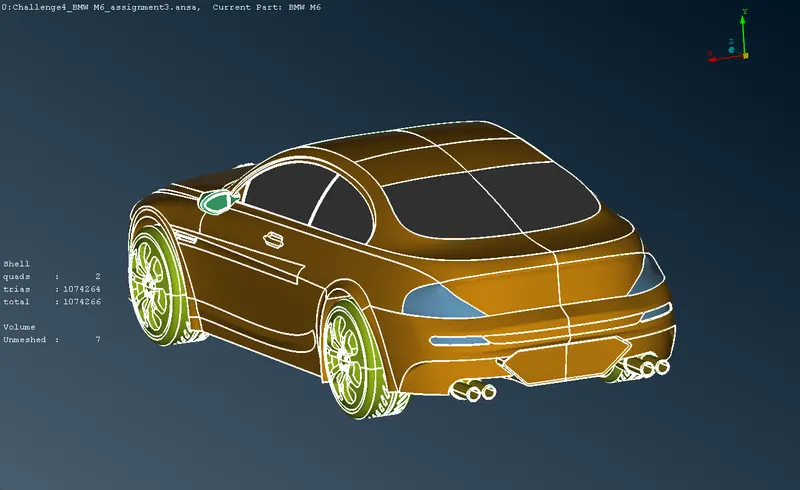
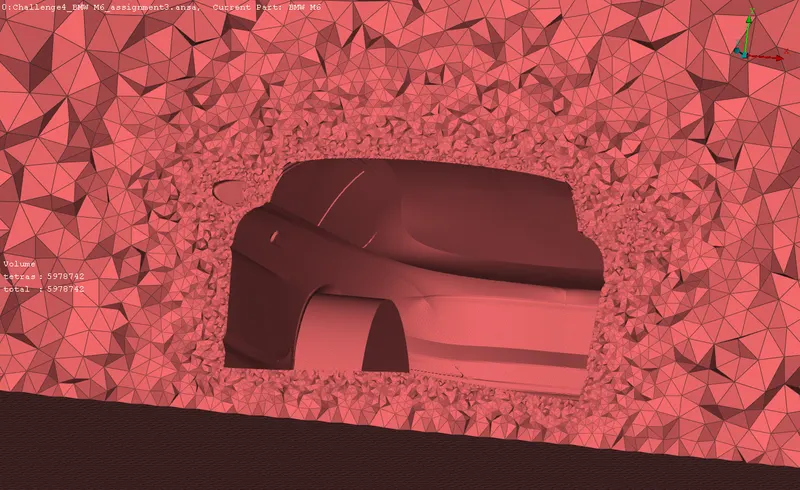
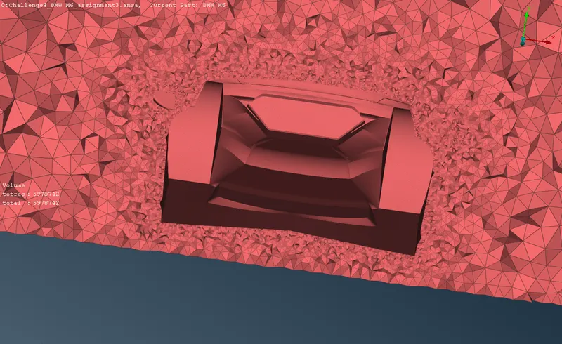
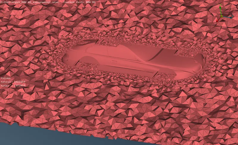
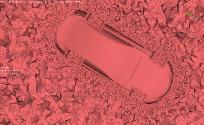
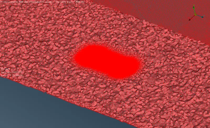
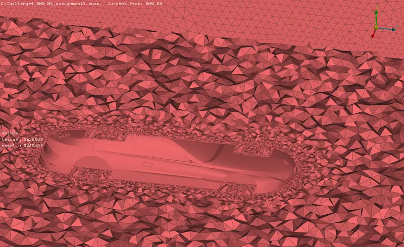
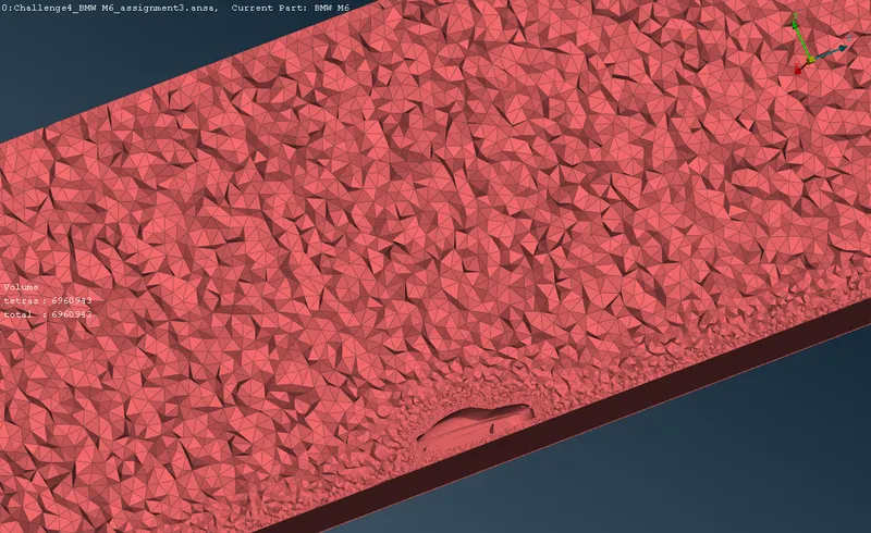
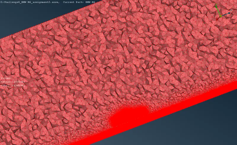
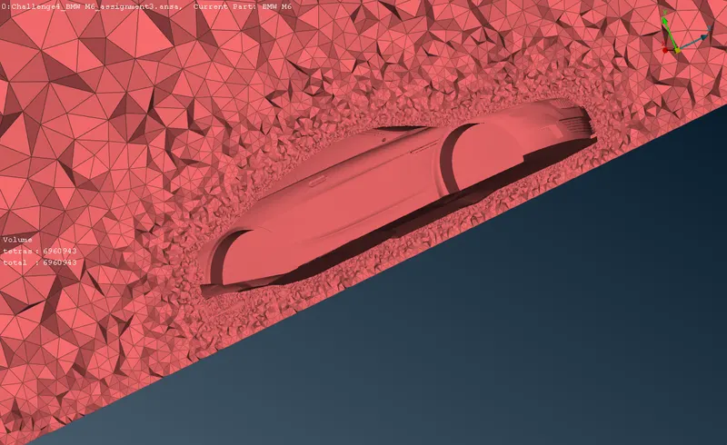
The single volume which remains is the volume between the wind tunnel and the car body. Remesh option is used to perform the volumetric mesh on the defined volume.
4 RESULT:
4.1 Car Surface mesh
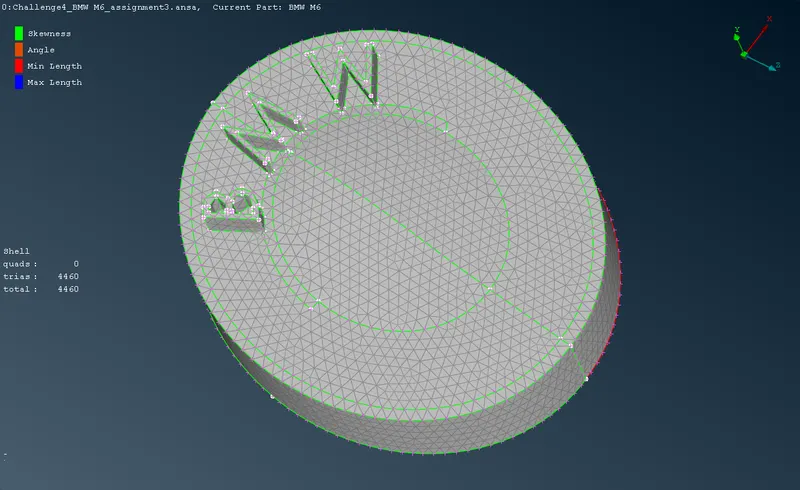
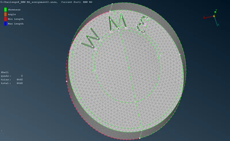
4.1.1 PID 1 - Hood Ornament:
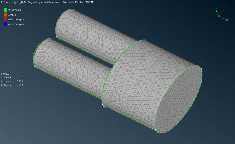
4.1.2 PID 2 - Exhaust:
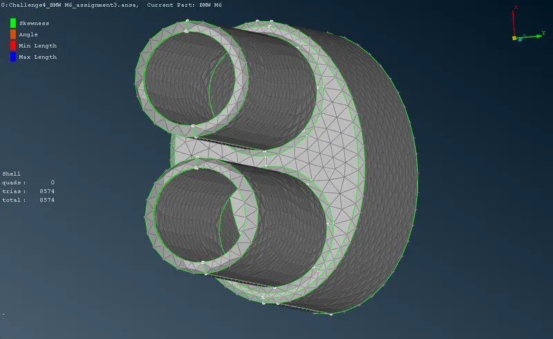
4.1.3 PID 3 - Lights:
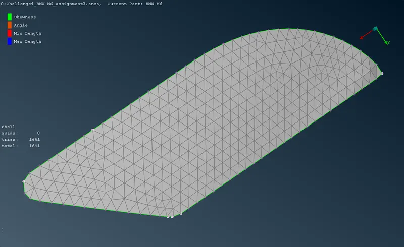
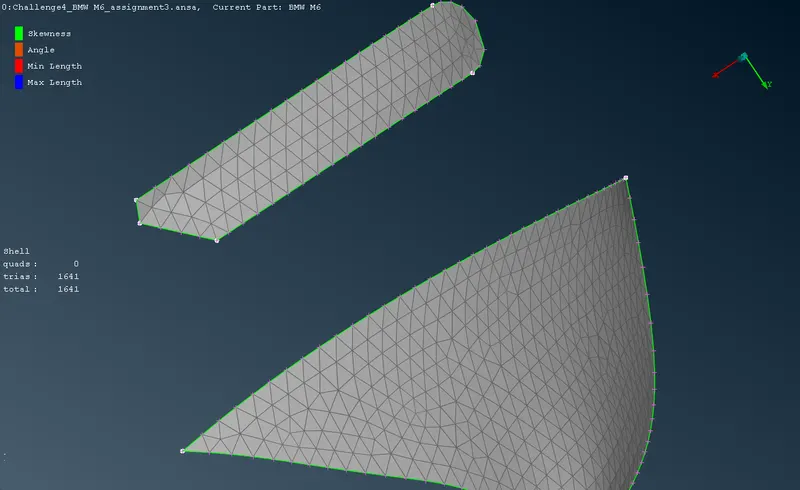
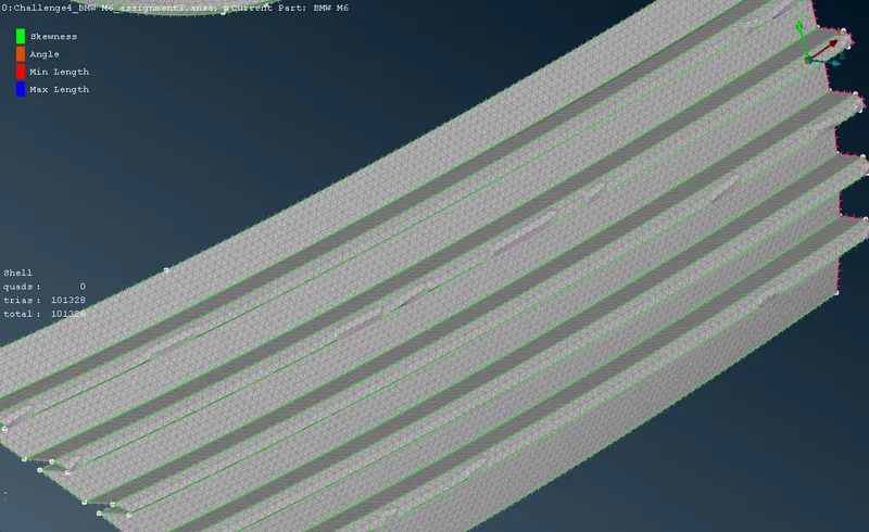
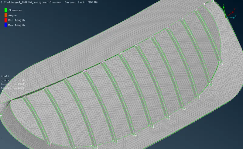
4.1.4 PID 4 - Grills:
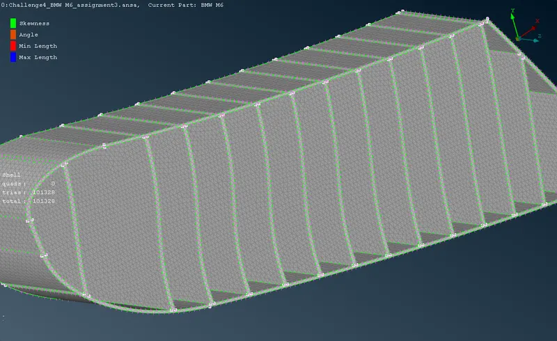
4.1.5 PID 5 - Rear view mirror:
4.1.6 PID 6 - Windshield:
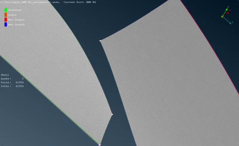
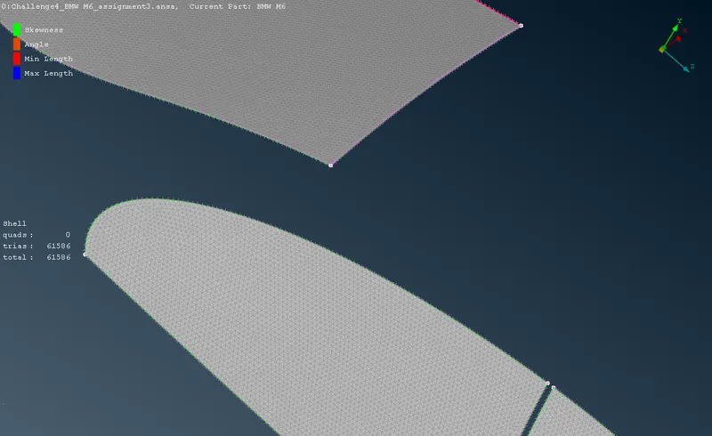
4.1.7 PID 7 - Rims and Tyres:
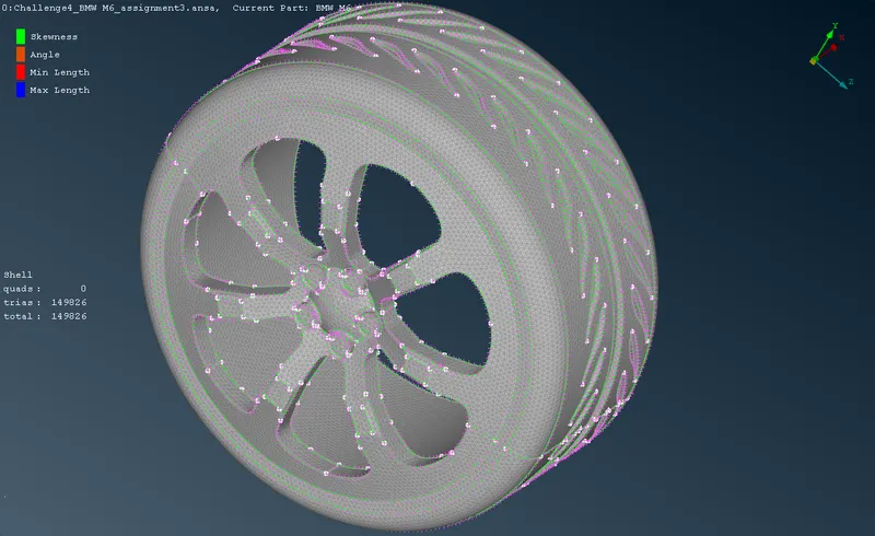
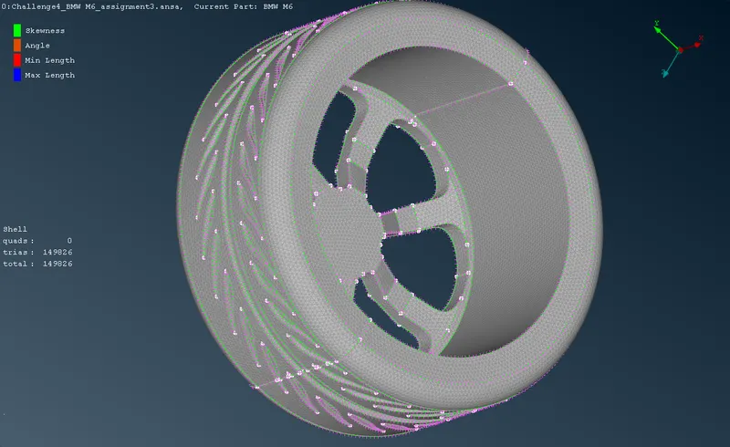
4.1.8 PID 8 - Body skin:
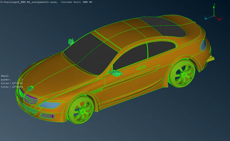
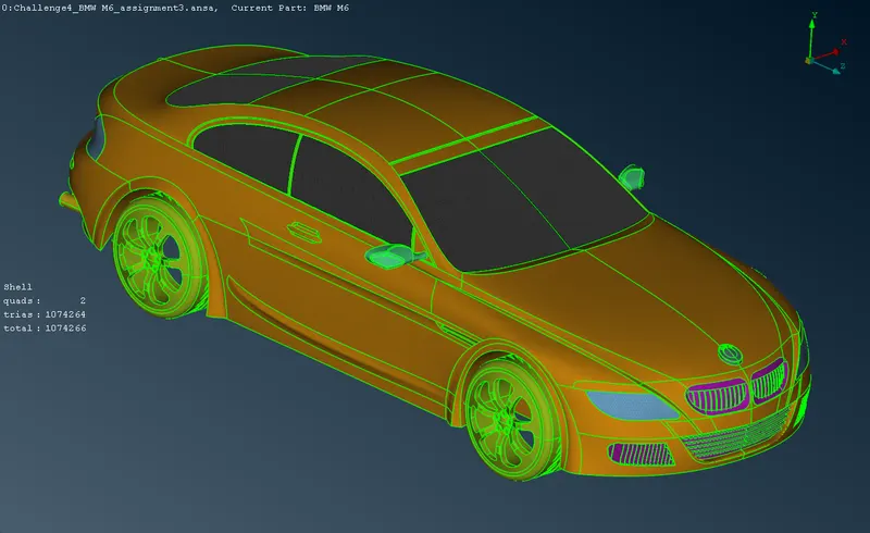
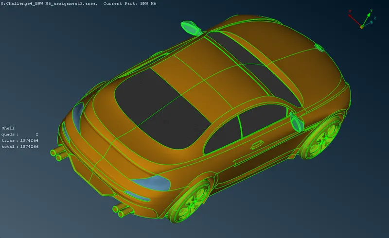
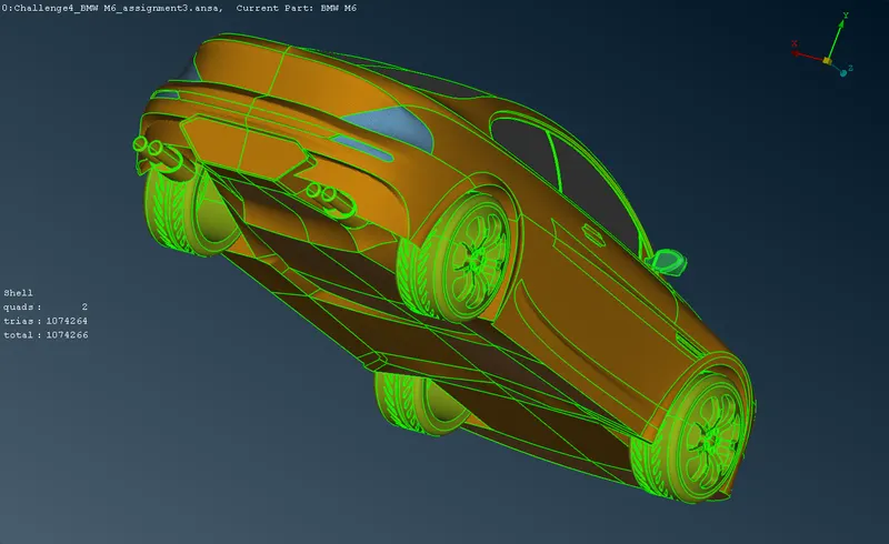
4.1.9 Full body surface mesh:
4.2 Tunnel surface mesh:
4.2.1 PID 9 - Tunnel side walls:
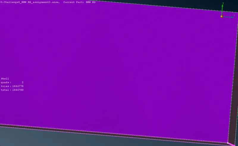
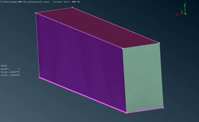
4.2.2 PID 10 - Tunnel rear and front faces:
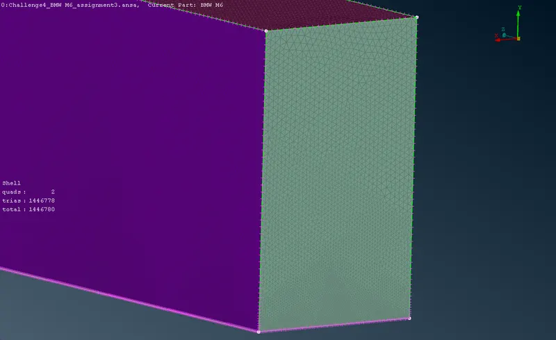
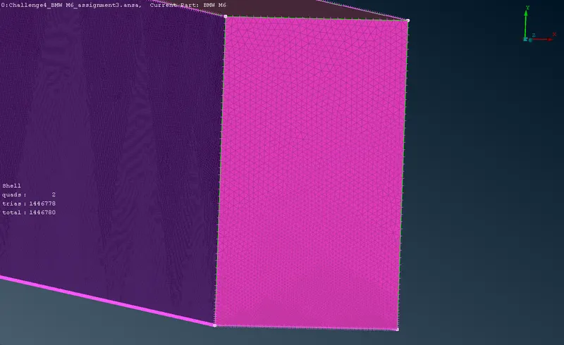
4.2.3 PID 11 - Tunnel roof and base:
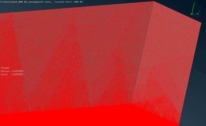
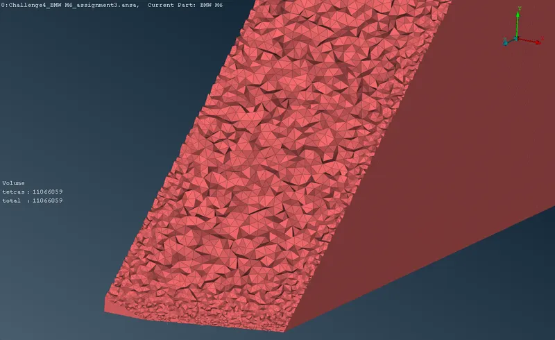
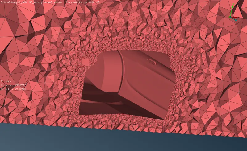
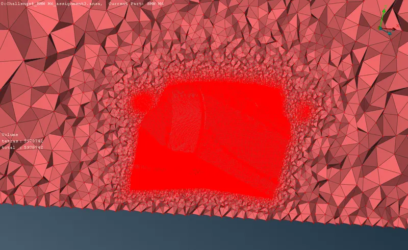
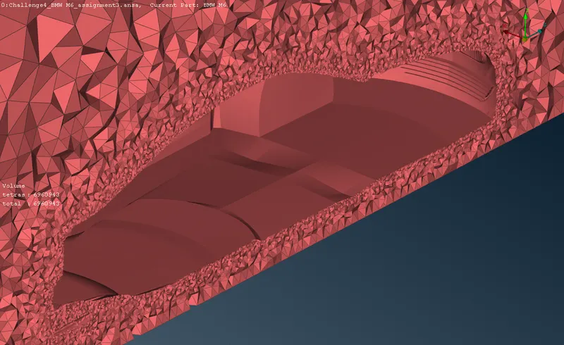
4.3 Volumetric mesh:
5 INFERENCE:
The topology cleanup is done on the car body with a variety of tool to get rid of the single and double cons. After the cleanup is done, the entities are meshed with individual mesh sizes based on the measurement made. The quality criteria is also rectified with the available tools for the 7 quality criteria which is necessarily determined. After all the quality criteria is rectified the entities are mirrored on the symmetry line to build the complete car body model along with the surface mesh.
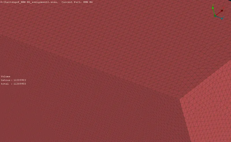
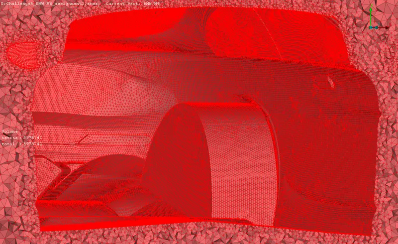
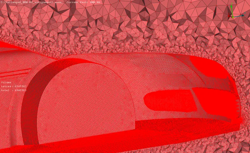
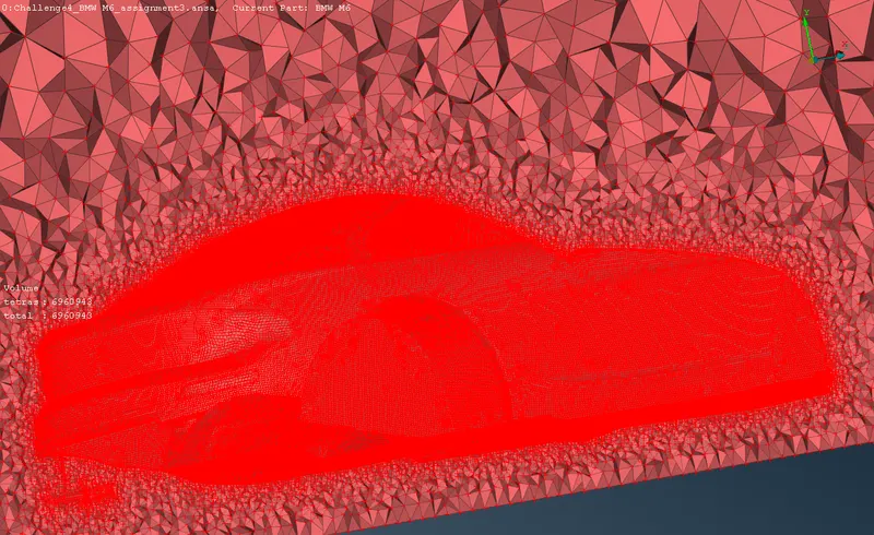
The wind tunnel is build with ideal dimensions and is meshed with roof and base having a uniform mesh. The walls can be observed having a mesh with linearly varying cell size. The cells at the bottom of the tunnel has a smaller cell size a 20mm and the cell size increases linearly up to 100mm at the roof surface. The volumetric mesh too has a similar kind of cell size based on the surface mesh. Further, the bottom side of the car has only 75mm of space which is filled with cells of the size ranging around 20mm, which is used to determine the CFD co-efficients.
The single volume is meshed with a finer mesh near the car and coarse mesh away from the car. This is essential for a CFD application in which all the variables have a major scope of solving near the car body. The area away from the car body near to the walls of the wind tunnel does not require an intense solving as the variables are pretty intact. This adds up to the accuracy of the results. In another way, this method also adds up to the efficiency of the solver, as the bigger cells gives a mesh with smaller number of cells. This saves the computing effort of the solver system, hence the efficiency.
The intricate features of the car has been addressed as the minimum size of the mesh cells has been determined from the measurements of the entities, hence the geometry is preserved which increases accuracy of the results. The check manager is a great in-built function which reduces the defect percentage in the mesh results. The geometry checks is run to ensure that the the geometry is perfectly fine for an error-free surface mesh which can be auto generated. The surface mesh is generated only if there are no anomalies detected. The same way the pre-surface mesh checks also provides a proof of the error-free surface mesh which can be used for volumetric meshing. Since there are no duplicates, interactions and overlaps found by the checks manager, the 3D meshed volume is a perfectly genuine mesh result.
6 CONCLUSION:
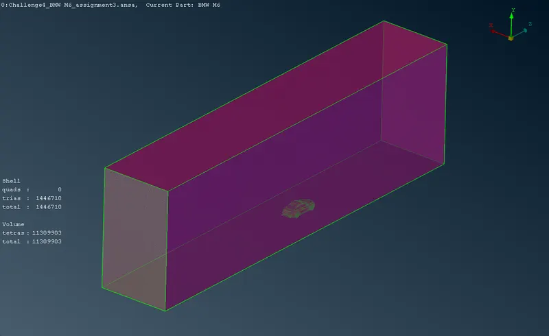
The volume generated is meshed with tetra cells and has 1,13,09,903 tetragonal 3d cells for a convenient application. The variable size of the grid elements can give an accurate and precise result for the solver. The surface has 14,46,710 2D triangular cells which formed the base for the volumetric mesh. The entire domain has an efficient mesh to facilitate an accurate solver result and also has optimum computing efficiency.
LINK TO THE ANSA FILE:
https://drive.google.com/file/d/10w8S_OPl0M8fLlNIzHksUTpBTFf153x9/view?usp=sharing