Week 3 Challenge : CFD meshing on Turbocharger
MESHING OF A TURBOCHARGER:
AIM:
To conduct surface and volumetric meshing on a turbocharger model.
INTRODUCTION:
CFD simulations are always the forefront of memory demanding CAE applications, as size of volume mesh used for them increases continuously. Current CFD simulations for external aerodynamics are performed on meshes of the order of hundreds of millions of elements, while billion size meshes will very soon no longer be considered as exotic. This imposes demanding challenges on the pre-processing software as it has to deliver te maximum mesh size, within the shortest time and all these on a limited amount of available hardware RAM. The Octree based Hexatreme algorithm of ANSA now provides CFD users with very fast mesh generation turnaround times, as it does not rely on watertight geometry or high quality surface mesh, and runs on multiple CPU threads. An appealing match to the automotive industry which deals with complex geometries and short development cycles. On the traditional bottom up approach of surface meshing and volume meshing is carried on in the case.
Volumetric mesh:
Typically volume meshes in three-dimensional are designed to conform to an underlying two-dimensional surface mesh, with volume mesh element size growing larger away from the surface. The surface mesh may be uniformly spaced or highly graded, and may have the fine resolution due to extrinsic mesh size concerns. When we desire that such a volume mesh have good aspect ratio, we require that some space-filling scaffold vertices be inserted off the surface.
Surface mesh vs volumetric mesh:
Surface meshes are two-dimensional elements - typically triangles or quads to approximately the outer surface of a 3D body. Surface meshes are used in manufacturing or rendering applications and CAE simulations.
Volume meshes also known as solid meshes, use three dimensional elements - typically tetrahedrons, hexahedrons, polyhedrons to define the surface and interior structure. Surface meshes can be converted into volume meshes to run FEA or CFD simulations.
PROCEDURE:
Step 1: Initial geometry check:
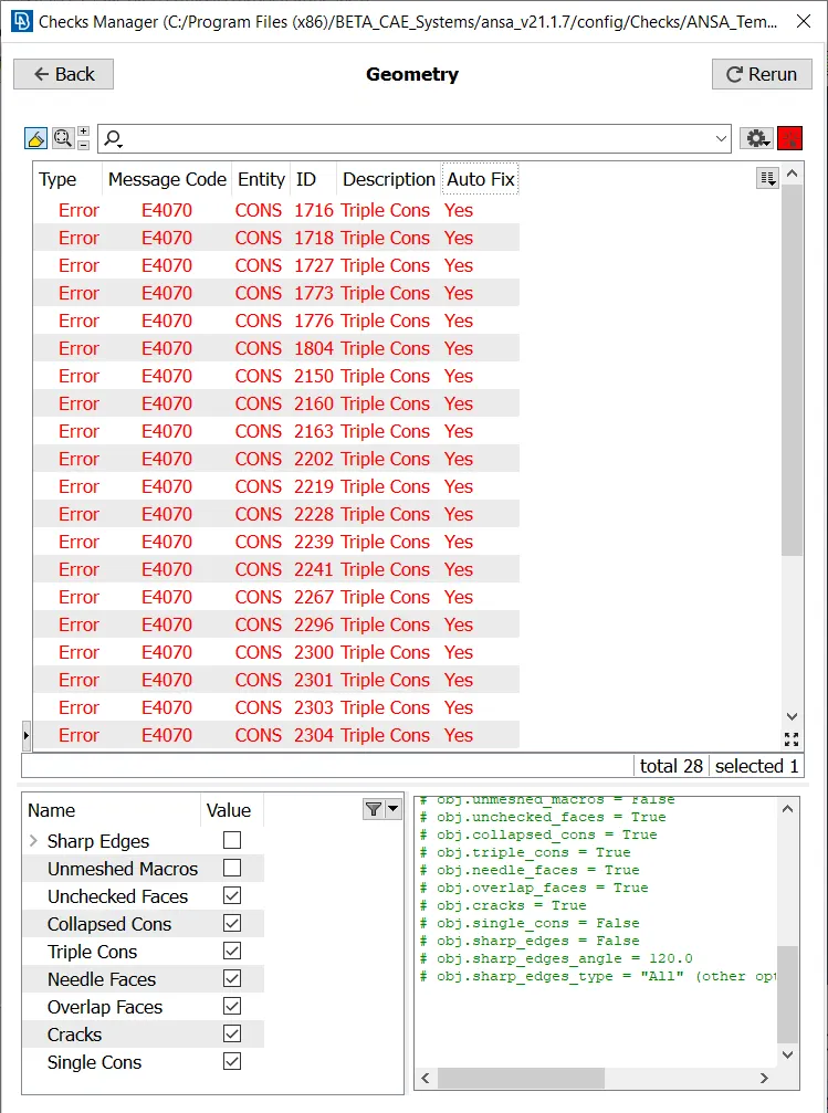
The given geometry is initially checked for all the errors due to single cons, triple cons, overlaps and cracks. The built-in Checks manager>Geometry checks is executed to find out all the anomalies automatically.
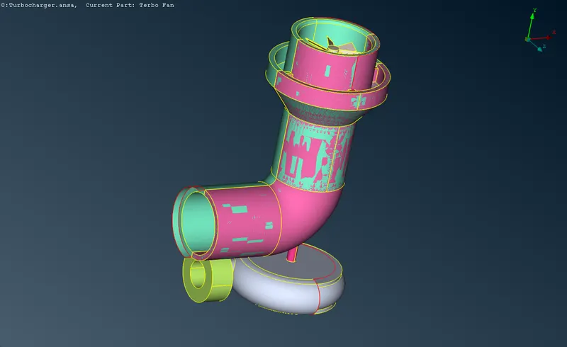
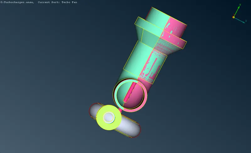
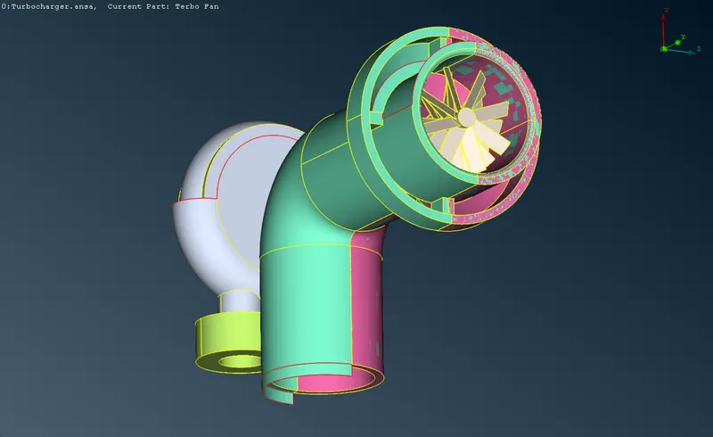
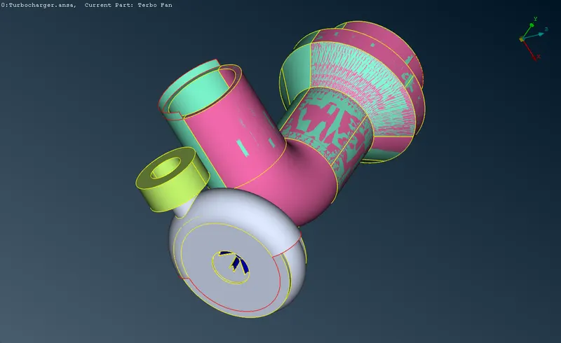
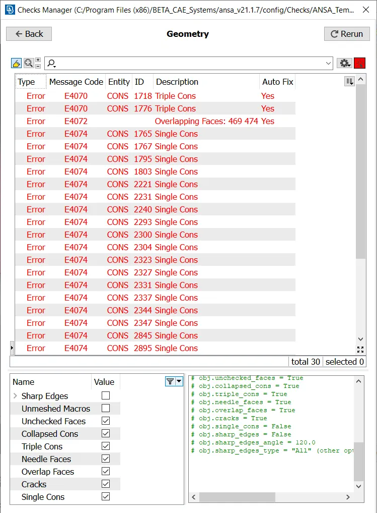
All the single cons, overlaps, cracks and intersections are to be resolved, while the triple cons has to be revised to be error free or unnecessarily present.
Step 2: Topology clean-up:
All the anomalies which are auto-detected by the checks are resolved one by one by using various tools in the Topo menu.
Step 2.1: Resolving single cons:
| Parametric tool is used to define hot points at the perimeter. New face>coons is used to create new face. | 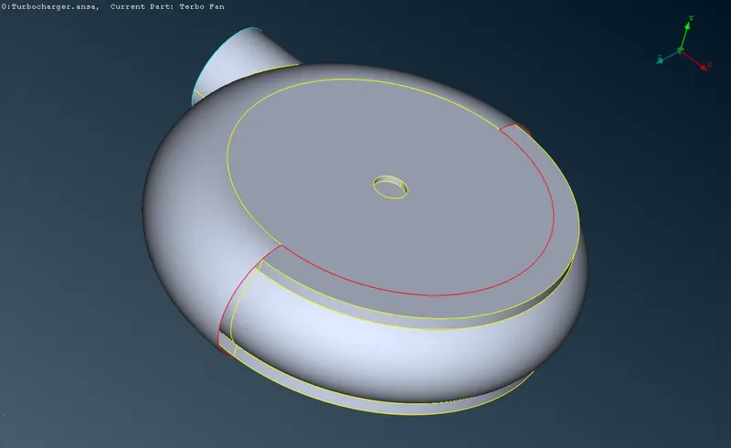 |
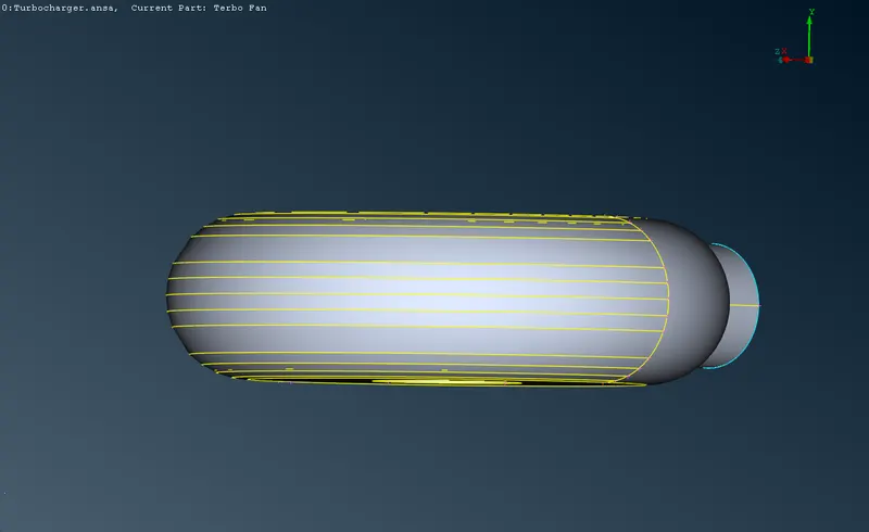 |
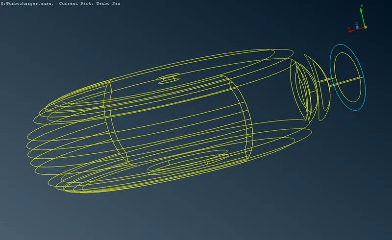 |
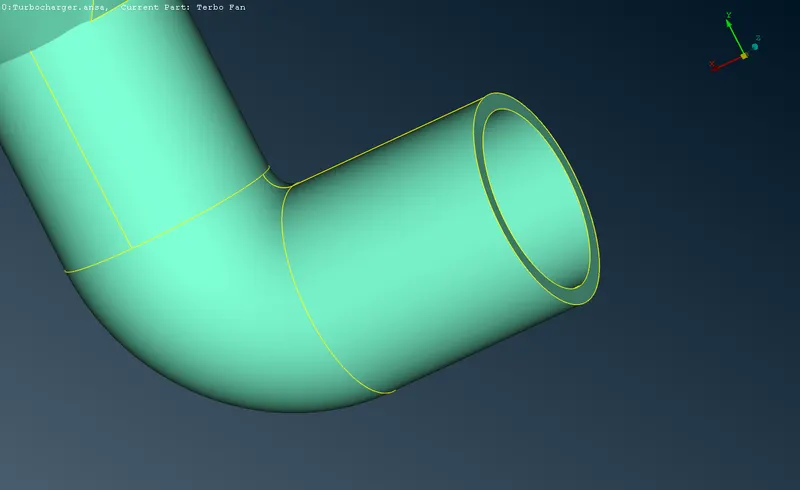
| This extended surface is deleted, and Fill Hole is used to create new surface. | 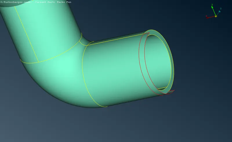 |
 |
|
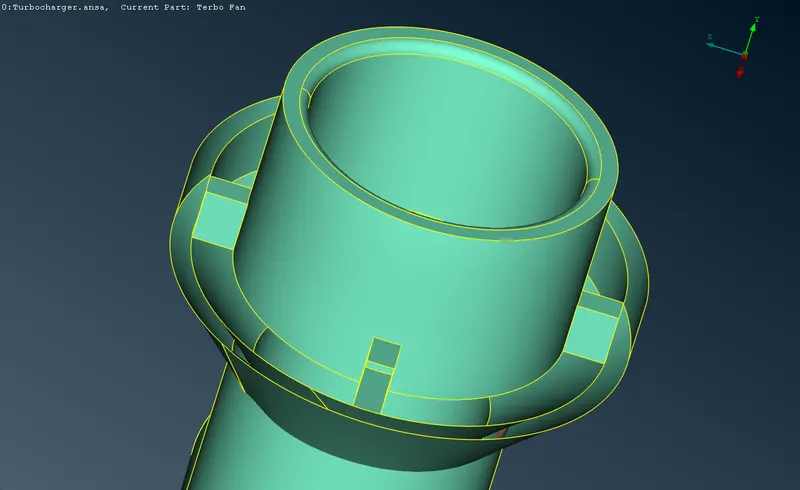
| Fill hole is used to create this entire cylindrical surface. | 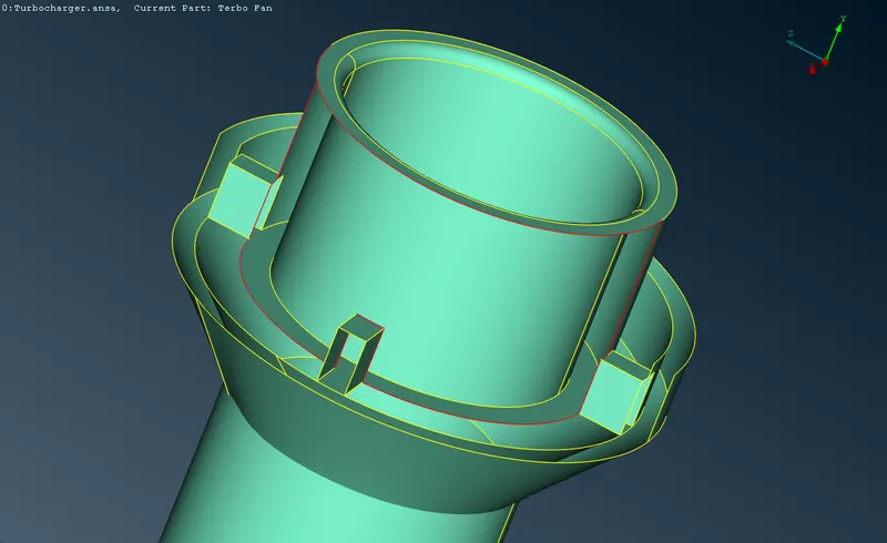 |
 |
|
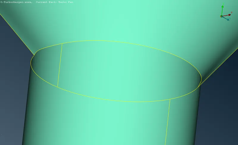
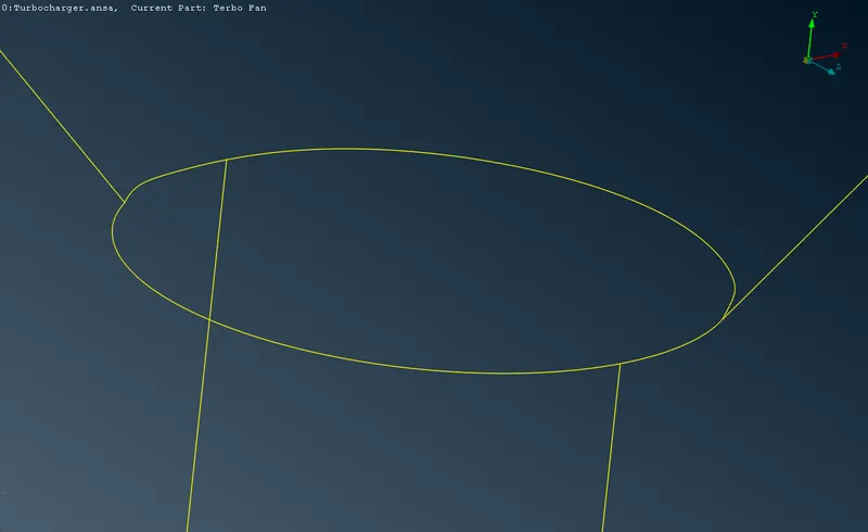
| Intersect tool is used to create a double cons, and the additional surfaces are deleted by the resulting option from the intersect tool. | 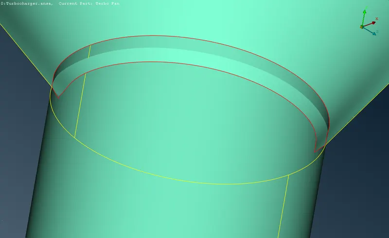 |
 |
 |
Step 2.2: Resolving triple cons:
| All these horizontal circular surfaces are deleted, and verified with the resulting double cons. | 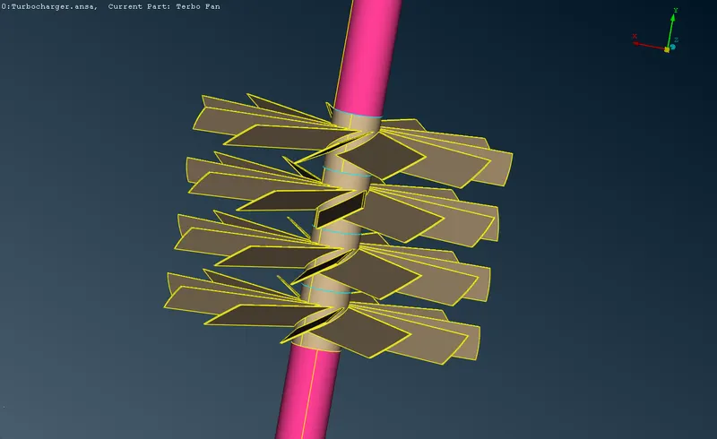 |
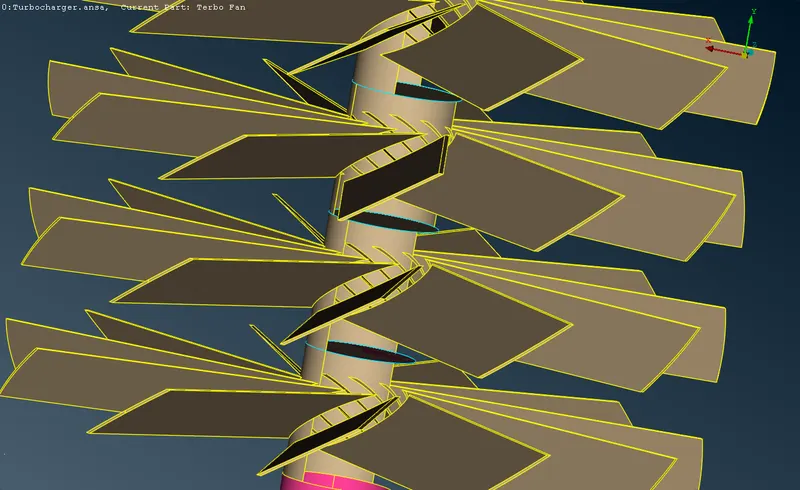 |
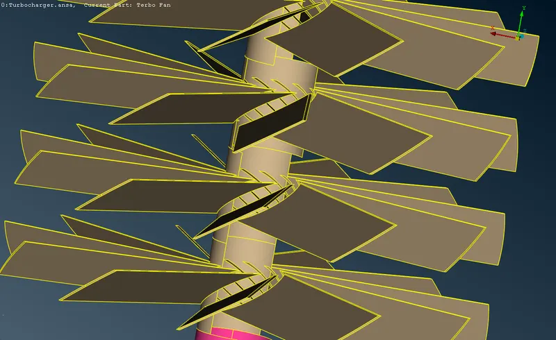 |
| All these horizontal circular surfaces are deleted, and verified with the resulting double cons. | 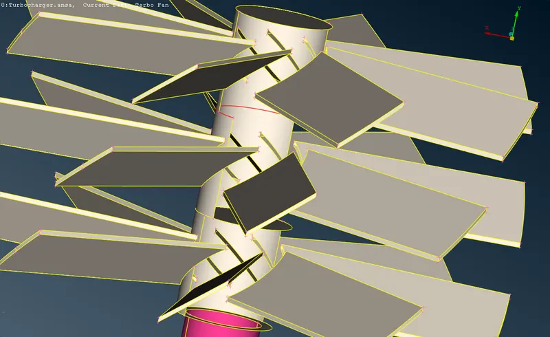 |
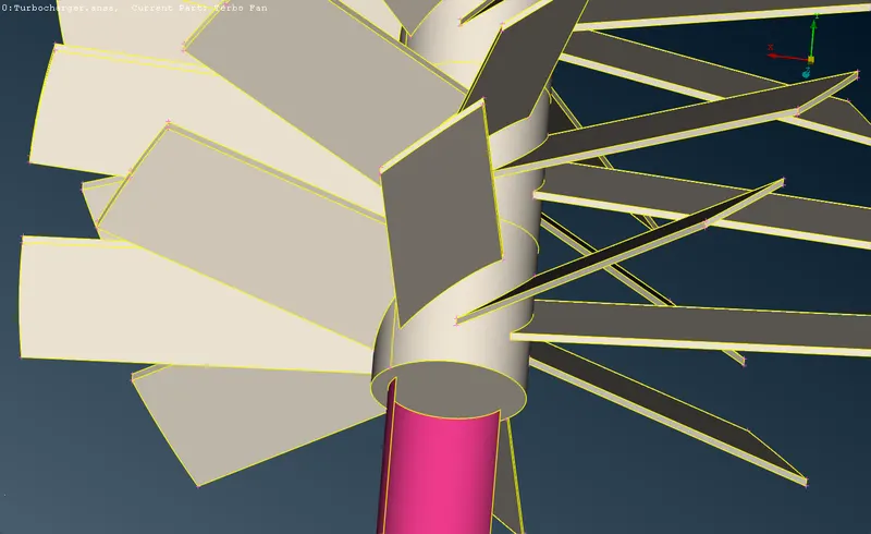 |
Topo tool is used to combine the remaining single cons to a double cons, after deleting the surfaces. |
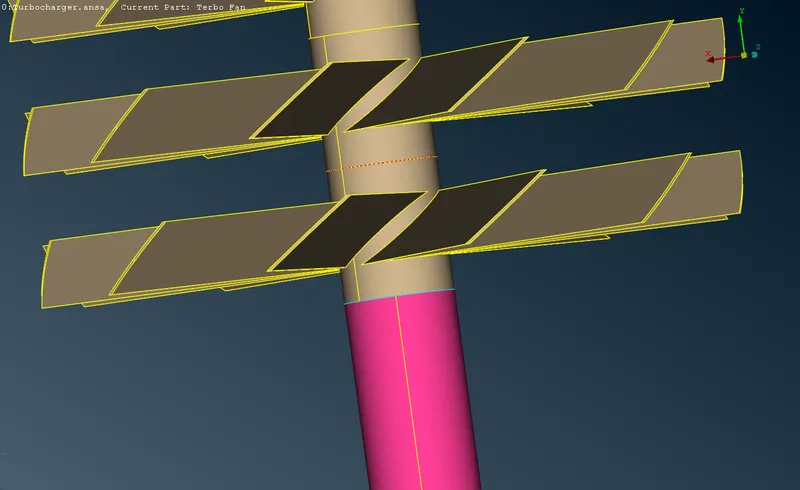
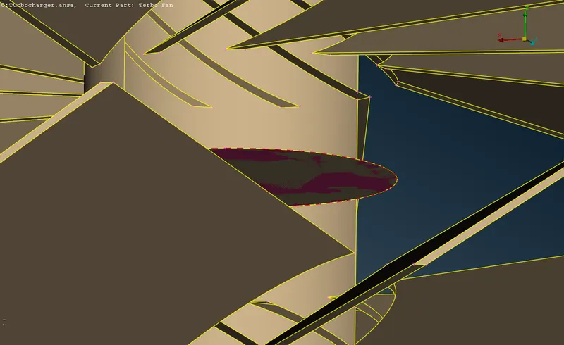
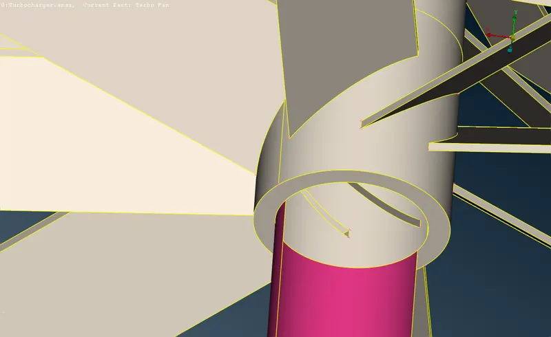
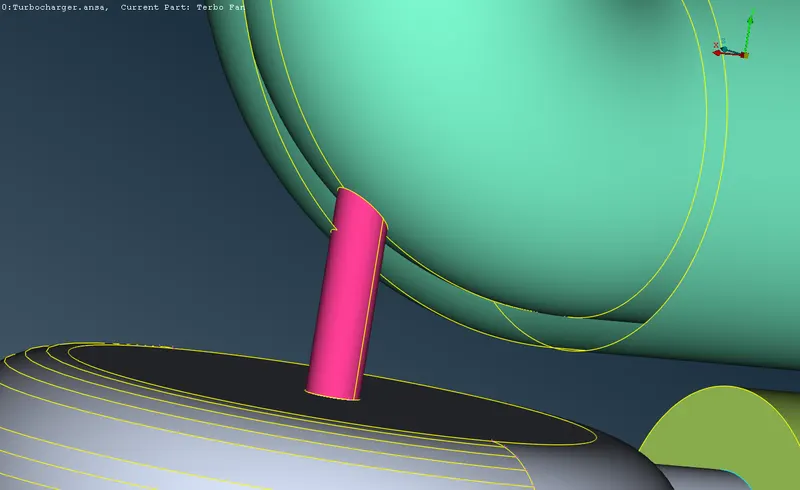
Step 2.3: Resolving overlaps:
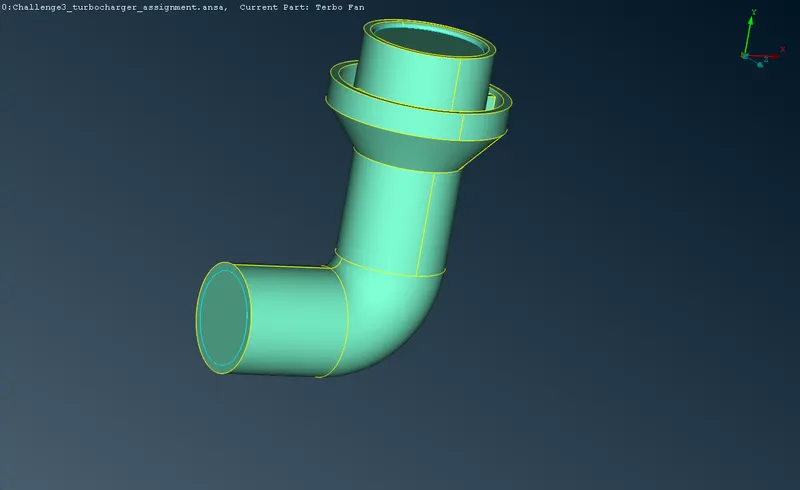
| This overlapping surface is deleted directly from the PID. | 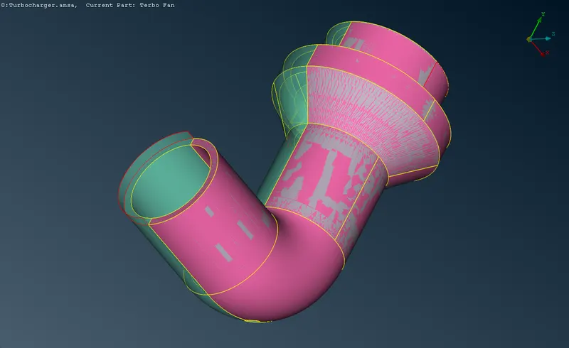 |
 |
|
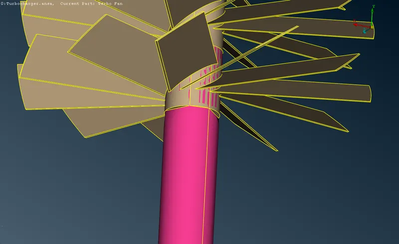
| This surface is selected individually and deleted. | 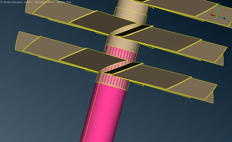 |
 |
 |
| This surface is selected individually and deleted. | 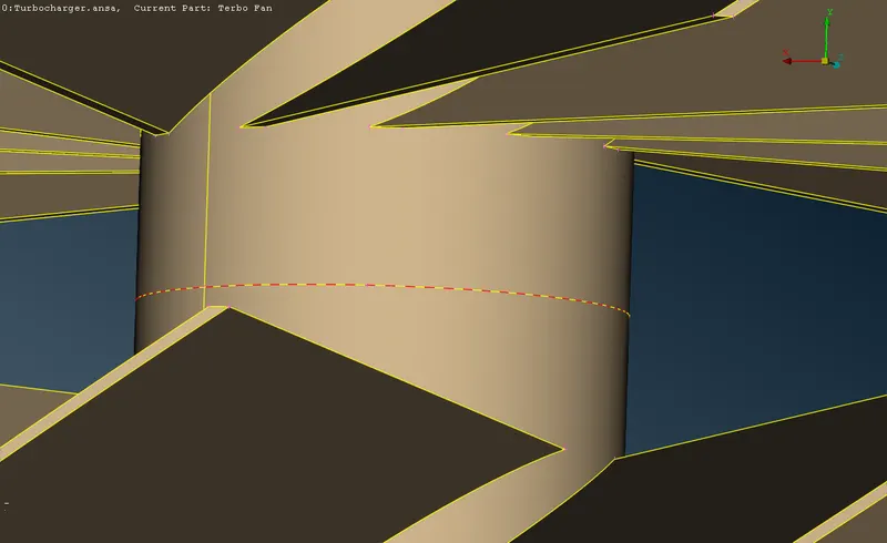 |
 |
|
| This surface is selected individually and deleted. | 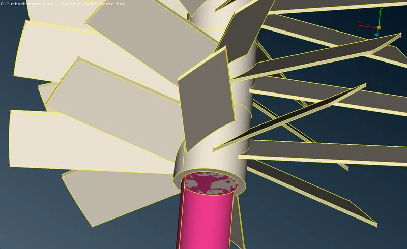 |
 |
|
| This surface is selected individually and deleted. | 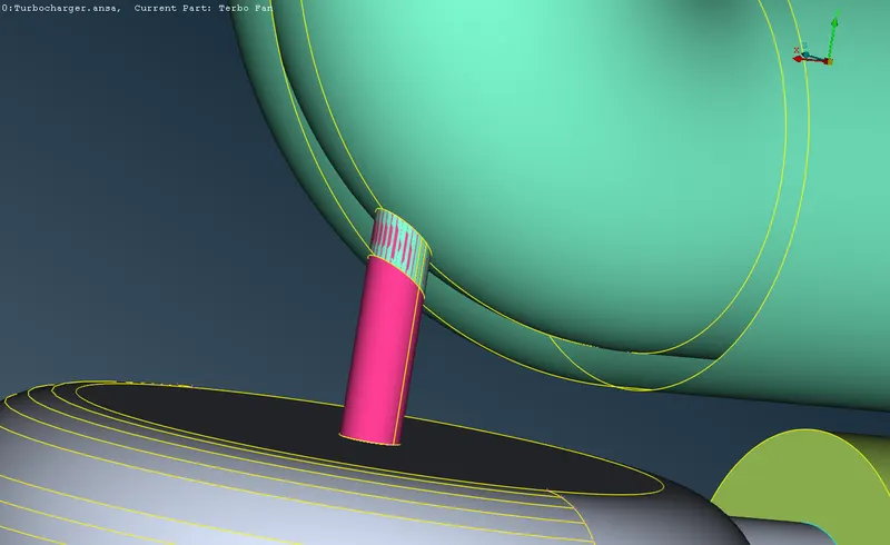 |
 |
|
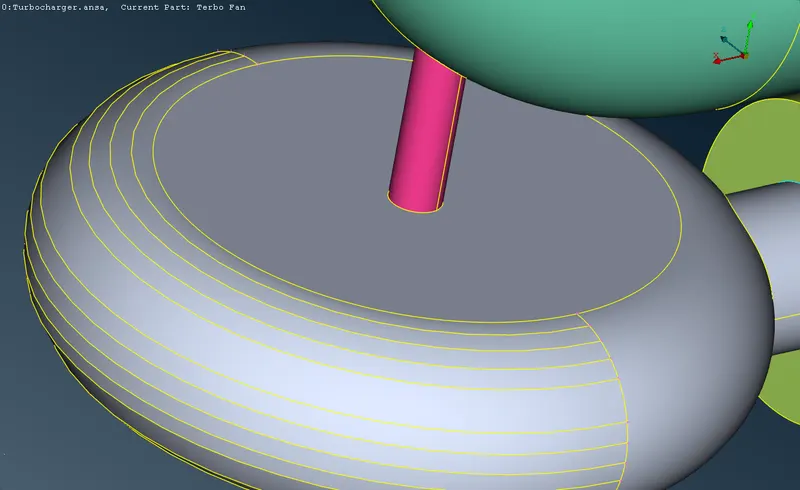
| This surface is selected individually and deleted. | 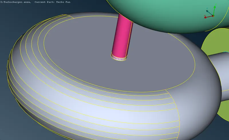 |
 |
|
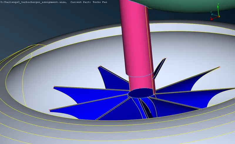
| This surface is selected individually and deleted. | 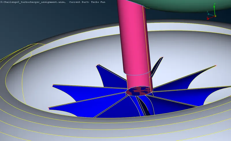 |
 |
Step 2.4: Defining a closed geometry:
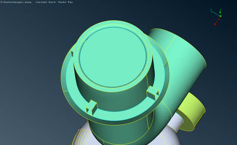
| All these surfaces which are open to the space are closed with a surface to confine the geometry as a solid volume. | 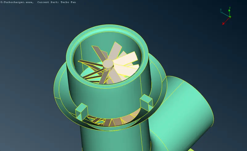 |
 |
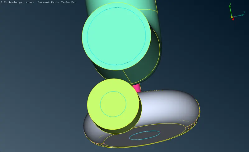
| All these surfaces which are open to the space are closed with a surface to confine the geometry as a solid volume. | 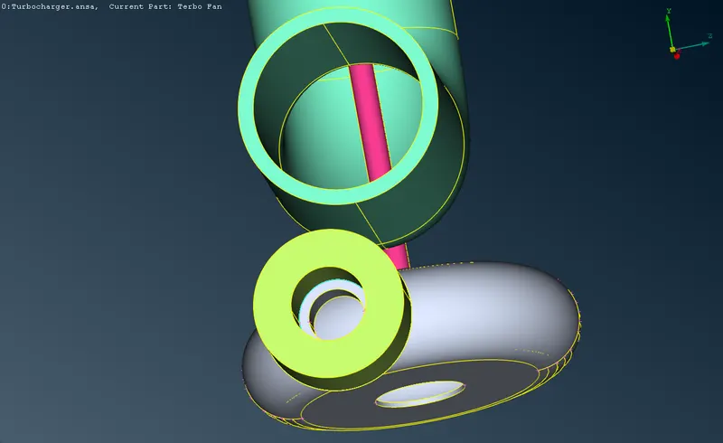 |
 |
Step 3: Final geometry check:
After resolving all the anomalies, geometry is again run to verify the error free geometry. All the single cons, overlaps, intersection are resolved, and the unnecessary triple cons are resolved, while the remaining triple cons are verified as necessary.
Step 4: Assigning PIDs:
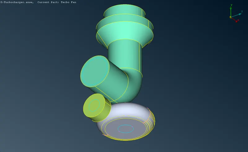
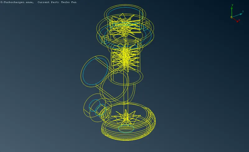
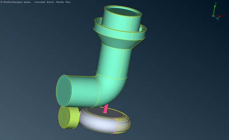
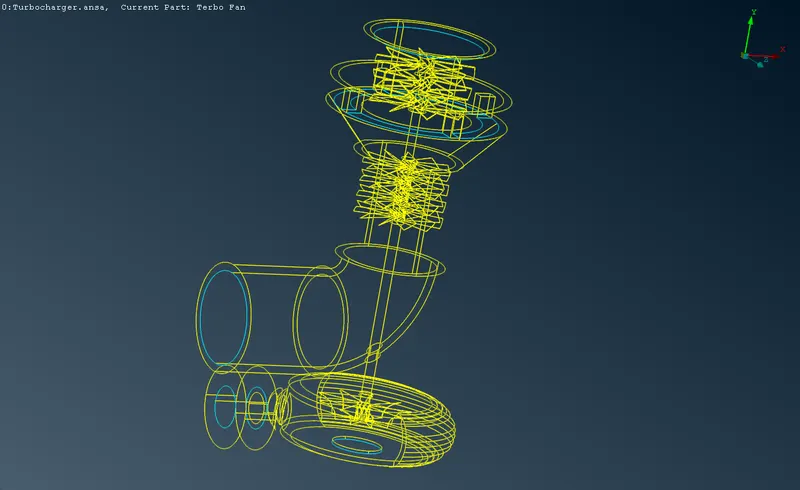
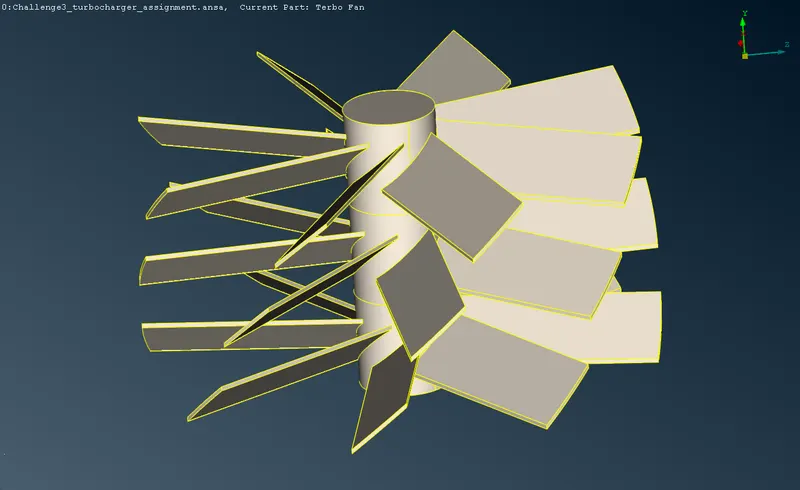
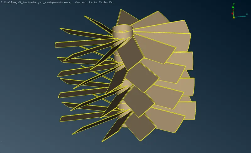
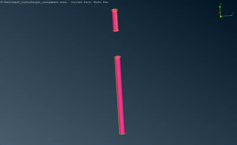
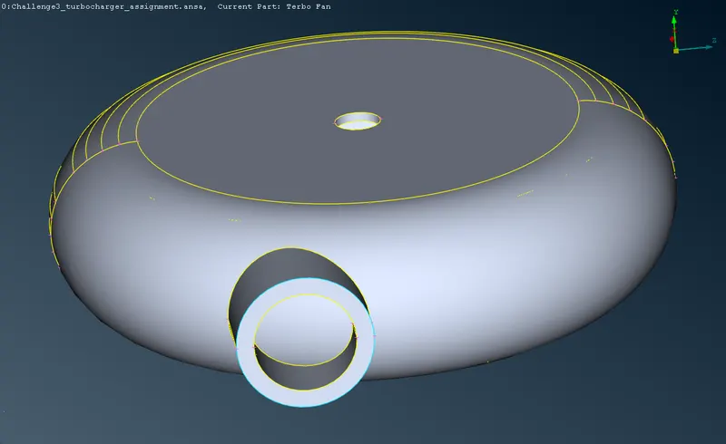
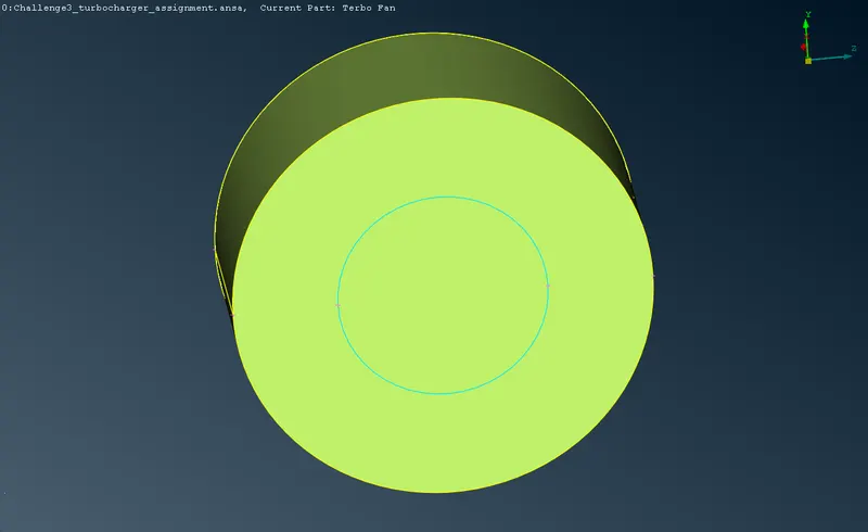
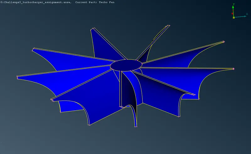
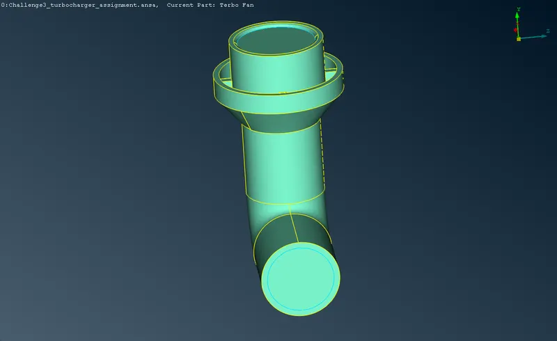
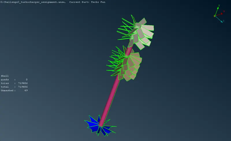
PIDs are assigned to separate geometries among blades stage 1, blade stage 2, the shaft, the impeller, the compressor casing, turbo casing and the inlet casing.
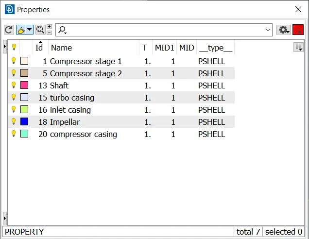
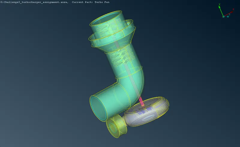
All the PIDs defined are visually represented by different colors.
Step 5: Surface meshing:
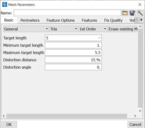
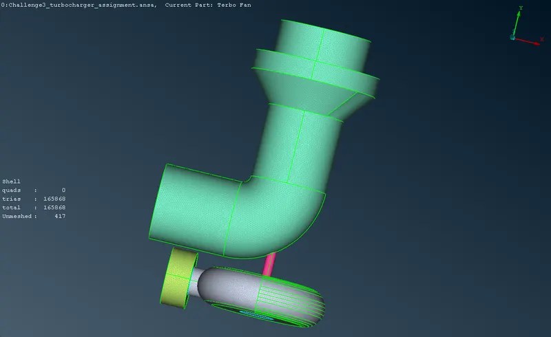
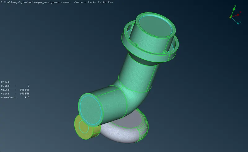
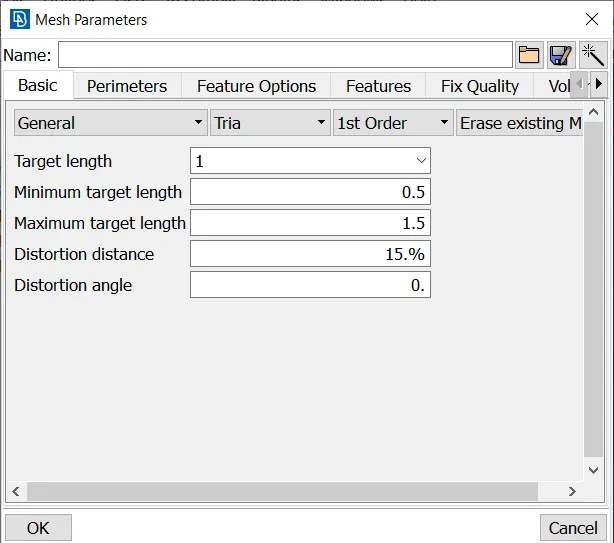
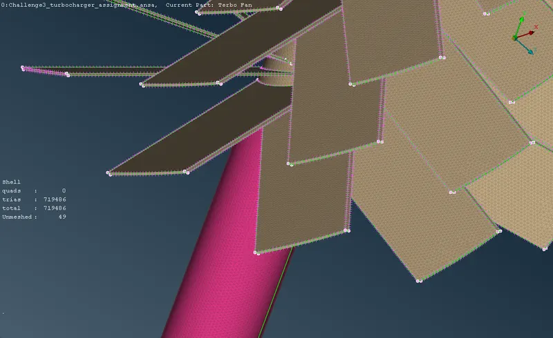
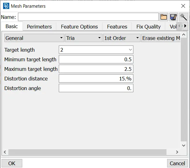
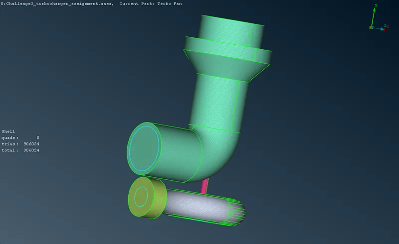
Different PIDs are surface meshed separately with different lengths according to the mean size of the geometry. Perimeter>Length, Macro>Length tools are used to define the lengths of the surfaces before meshing. Min and max length based on the target length is defined.
 |
 |
 |
 |
 |
 |
 |
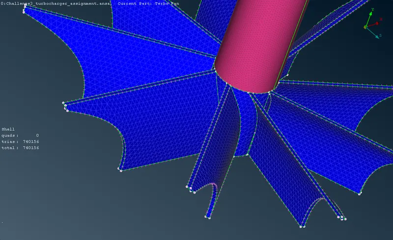 |
Spot Mesh > Select, Tria method tool is used to mesh individual surfaces by selecting based on various PIDs defined.
Step 6: Preparation for volumetric meshing:
After surface meshing, Pre-surface-meshing-checks is done to make sure, the geometry properly meshes on the surface and the anomalies if detected is resolved, before doing a volumetric mesh.

Step 7: Volumetric meshing:
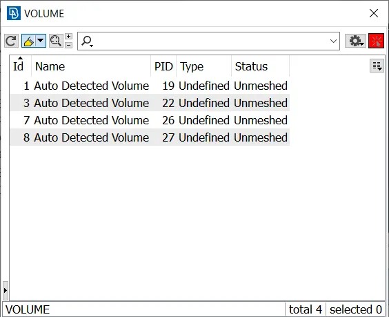
Define > Auto detect tool is used to define the various volumes of the geometry. The volumes which are the thickness of the present geometry are deleted, and only the voids are kept as the meshing volumes.
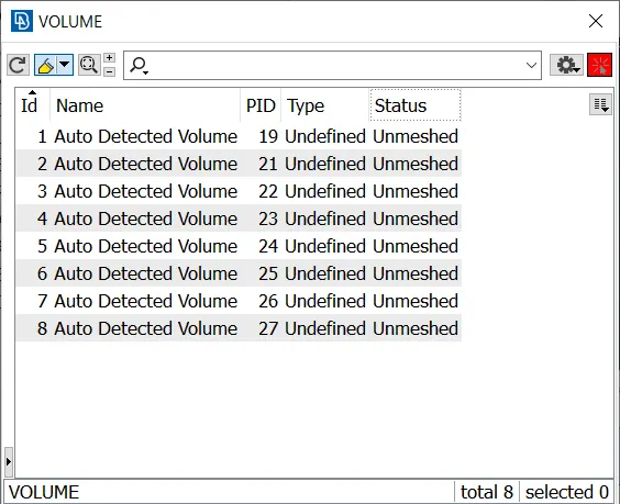
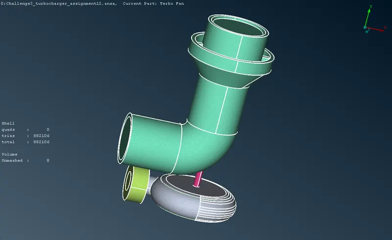
The auto detected volumes 21, 23,24,25 are deleted as they are the thickness elements of the geometry.
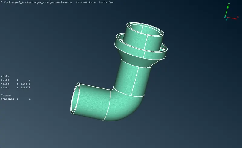
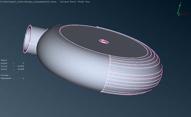
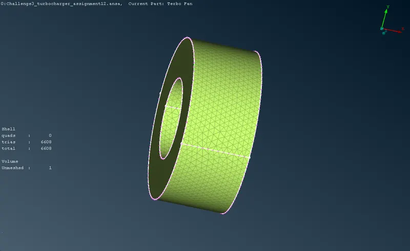
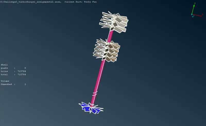
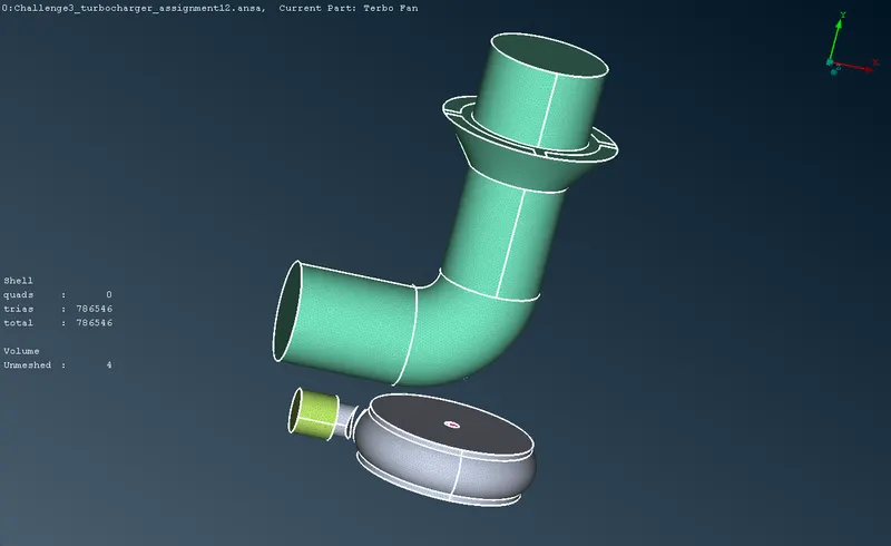
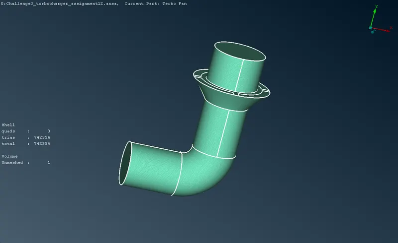
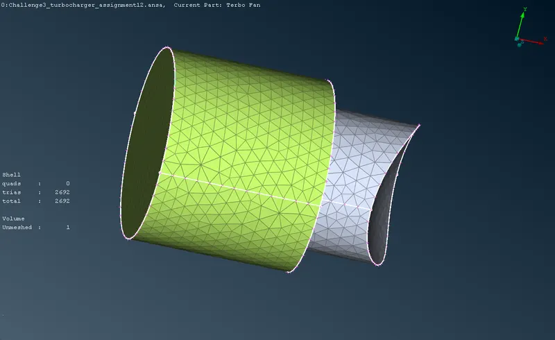
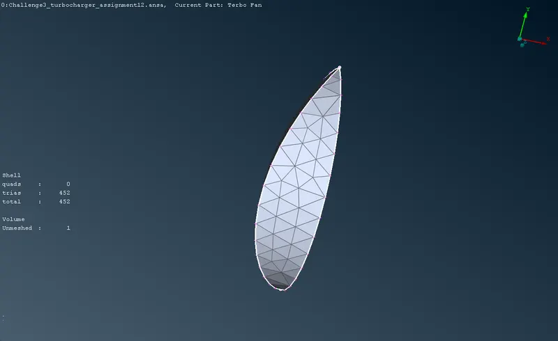
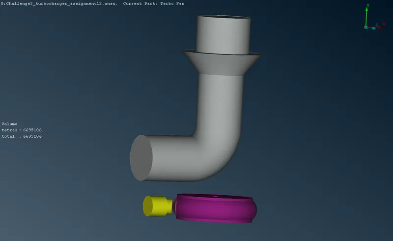
The auto detected volumes 19,22,26,27 are meshed by using Remesh> Tetra CFD to obtain tetrahedral cells in the volumetric mesh.

RESULTS:
Surface mesh:
 |
 |
 |
 |
 |
 |
Volumetric mesh:
 |
 |
 |
 |
 |
 |
INFERENCE:
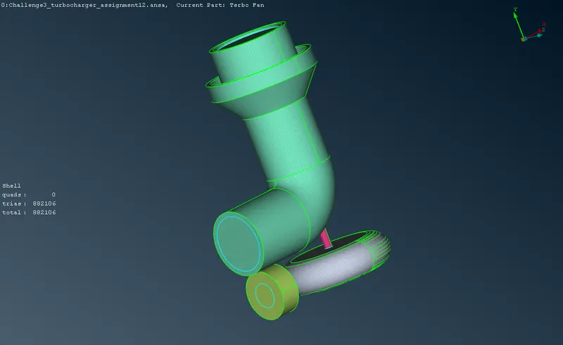
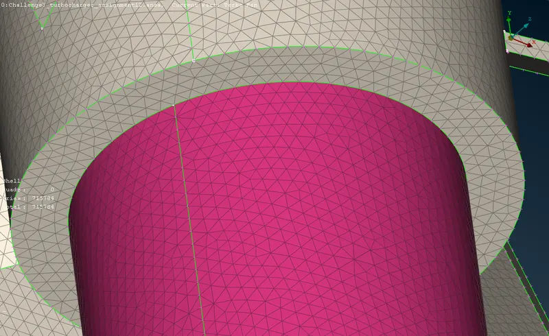
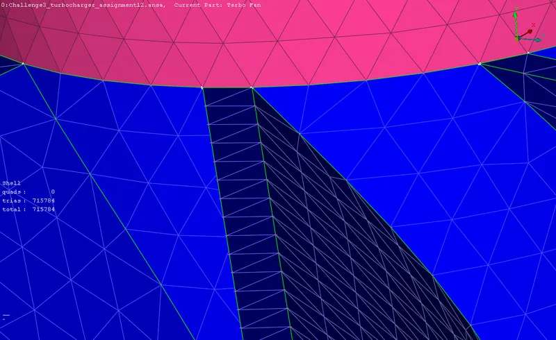
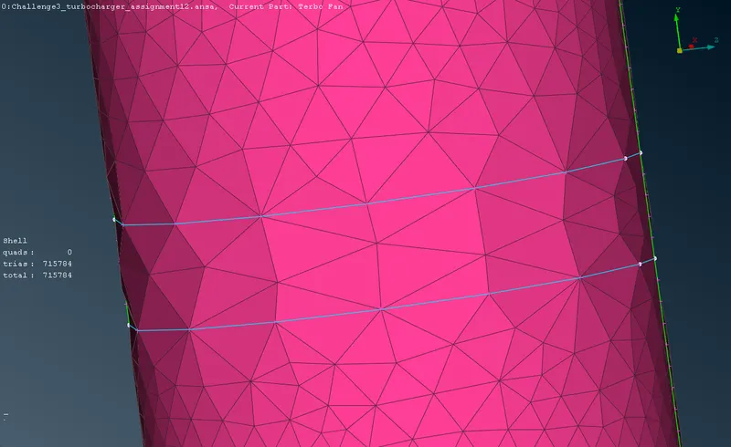
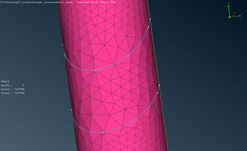
Surface mesh: From the images, it is observed that different sizes for different entities must be used to obtain a perfect meshed geometry which can be used in advanced CFD simulations. The blades of the compressor and their shaft are given a mesh length of 1mm with min size of 0.5mm and max size of 2mm. The impeller length is given as 2mm with min 1mm and max 3mm. The casings are given a size of 5mm with min 3mm and max 7mm. Measure tool is used to verify the meshed surface to be in accordance with the defined max and min lengths. The number of triads in noted to verify the quality of the surface mesh. Triads are the result of the tria method defined during the surface mesh generation. A total of 8,82,106 triads are formed in the surface mesh.
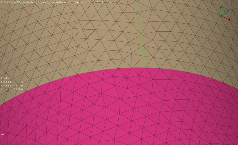
Conformal mesh: The surface mesh at the interfaces are observed to have a conformal mesh. The nodes and cells at the adjoining interfaces are assured to be concurrent. This is the result of the mesh length being a range of values rather than being a single average value. In addition to this, the triple cons formed during the topology cleanup is the adjoining interface of the surfaces transforms to a conformal mesh during the mesh formation. This is evident from the above images. The shaft seemed to have an average element size of 1mm with cells of the range 1mm to 2mm at the interface region of the shaft and the impeller.
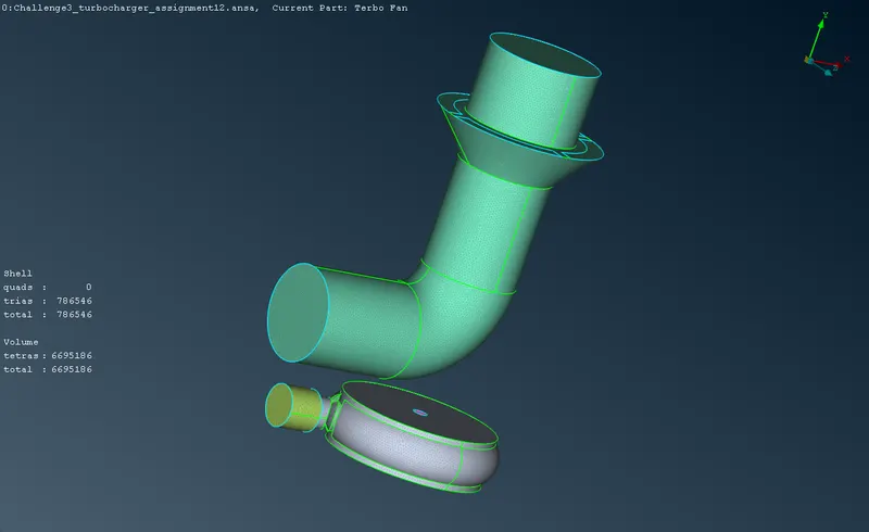
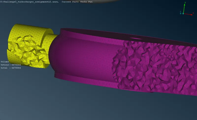
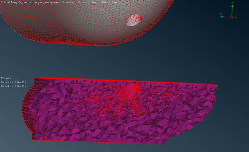
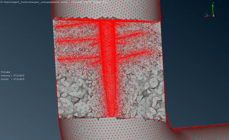
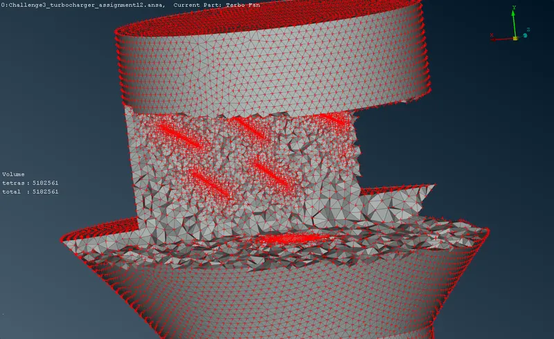
Volumetric mesh: The void elements of the volumes which are auto detected are meshed successfully, which is observed in the images. the element sizes are transformed from the surface mesh elements directly. The conformal mesh is also successfully transformed from the surface mesh. The various entities of the blades inside the casing in analysed visually by using the grid points display. The compressor casing has the shaft and the compressor blades which has fine mesh with average elements size at the interface of the surfaces. The same mesh is seen observed at the turbo casing and the impeller interface. A total of 66,95,186 tetras are formed in the volumetric mesh.
CONCLUSION:
Thus the given turbocharger model is cleaned up for the topology anomalies, and the volumetric meshing is carried out after surface meshing. The checks at the various levels are executed and then the meshing is carried out. 8,82,106 triads at the surface and 66,95,186 tetras are formed at the volumetric meshes.
LINK TO THE ANSA FILE:
https://drive.google.com/file/d/10vLE6LzqawzeHdivR4d20fxqMI-c6SGx/view?usp=sharing