Project 1 : CFD Meshing for Tesla Cyber Truck
CFD MESHING OF TESLA CYBER TRUCK SHELL
1 AIM:
To perform the volumetric meshing of a Tesla Cyber Truck with quality optimization, inside a Wind tunnel by a step by step process of geometry clean-up and surface meshing.
2 INTRODUCTION:
ANSA has a long history of development and application throughout many industries, namely automotive and motorsports, aerospace, energy, marine, and more. Its main characteristics are the ability to generate high-quality meshes for any CAE sector and for many commercial and academic codes. Specifically for CFD, it supports native output for all major CFD codes like ANSYS Fluent and CFX, STAR CCM+ , CFD++, DLR's TAU etc. In addition it supports CGNS I/O enabling it to provide meshes for all other CFD codes in the aerospace, defence sector and the academia. Of course for our specific investigation, ANSA provides support of native I/O for OpenFOAM, including the boundary conditions and solver setup.
ANSA is a complete pre-processing package, so all the required operations can be performed within its environment. From geometry import, check and clean-up to watertight preparation and controlled defeaturing if needed, to unstructured surface and volume meshing and finally to output. It also supports structures hexa meshing and even morphing of mesh and geometry for optimization studies. All element types are supported, standard and polyhedral.
The ANSA meshing process is bottom up, meaning that once the geometry is clean and watertight, surface mesh is generated and then extruded inwards to generate boundary layer elements and finally the remaining volume is filled with a volume mesh of typically hexahedral or tetrahedral elements.
The meshing process is automated via the ANSA Batch Mesh tool, a template-driven process that can be setup once, and then run automatically on different geometries. Batch mesh automation in ANSA is the result of the demands of the automotive industry to efficiently create consistent meshes in a purely automated and repeatable process that can be applied again and again during the design process for each design modification. In the motorsports industry for example, hundreds or thousands of design iterations may be examined in a week. It is therefore a necessity that meshing is a fully automated, consistent and error-free process.
3 PROCEDURE:
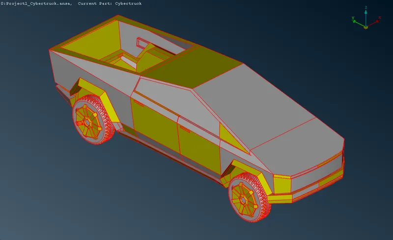
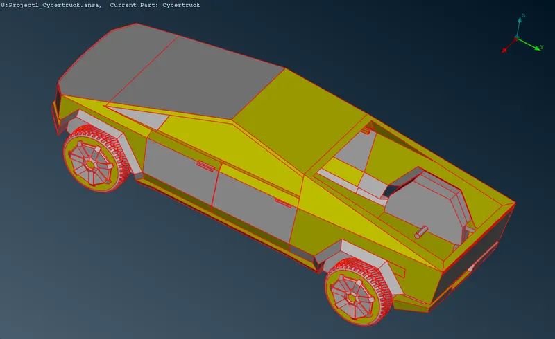
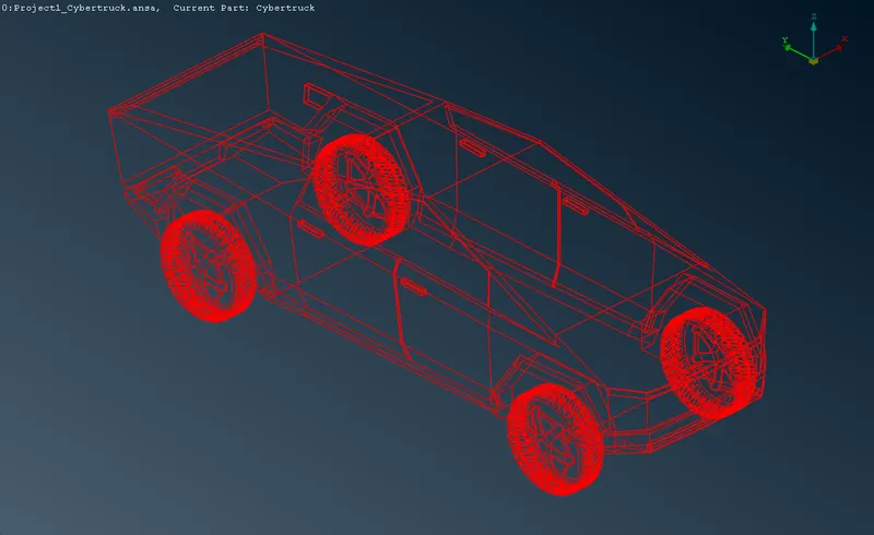
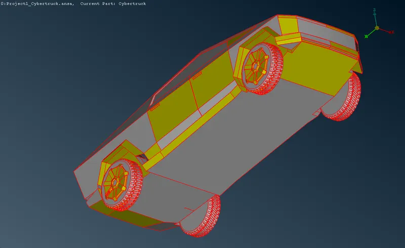
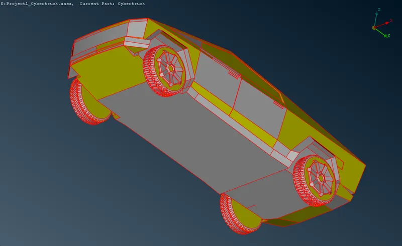
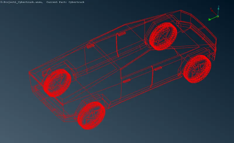
The initial geometry is observed to have a variety of entities with different PIDs and the same MIDs. The cons resolution is set to optimum initially before the beginning of the process.
3.1 Topology optimization:
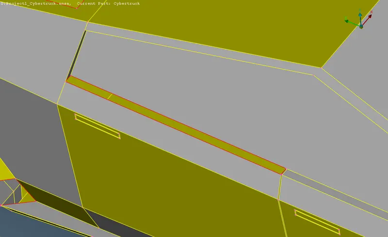
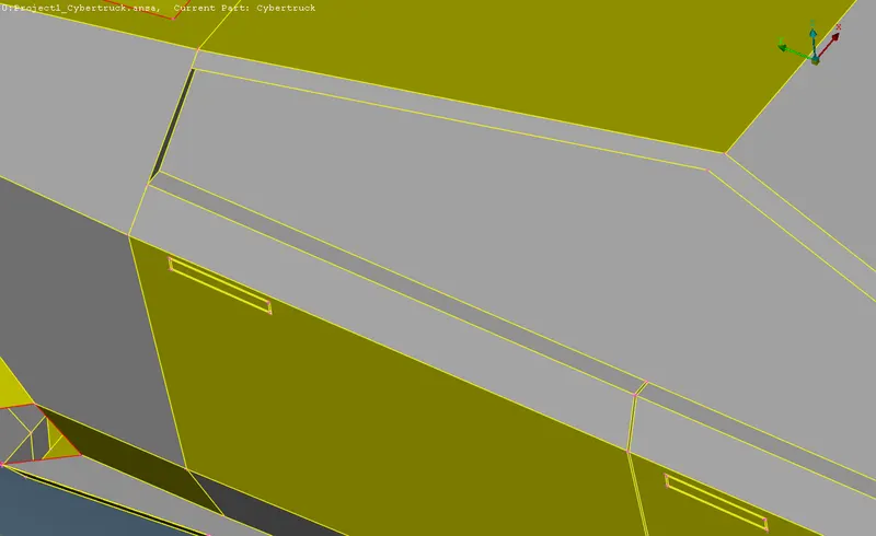
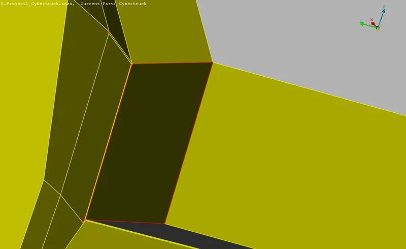
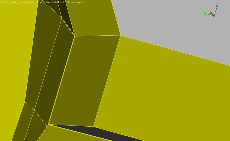
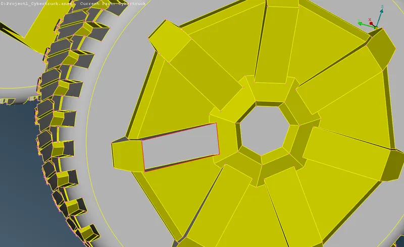
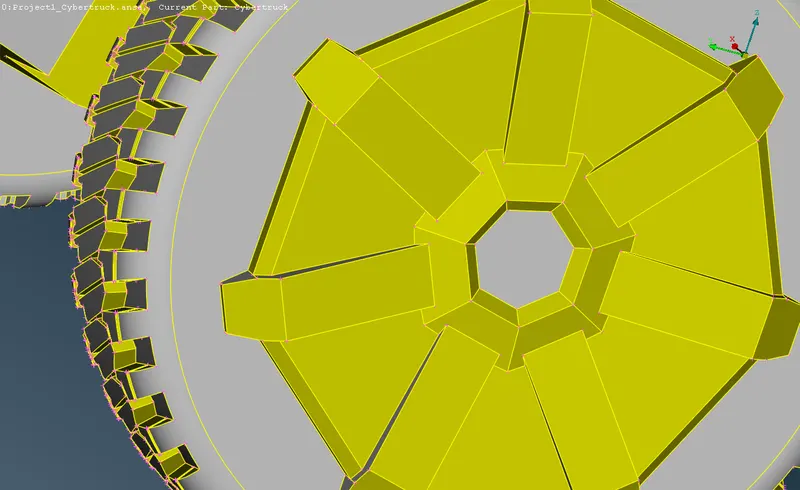
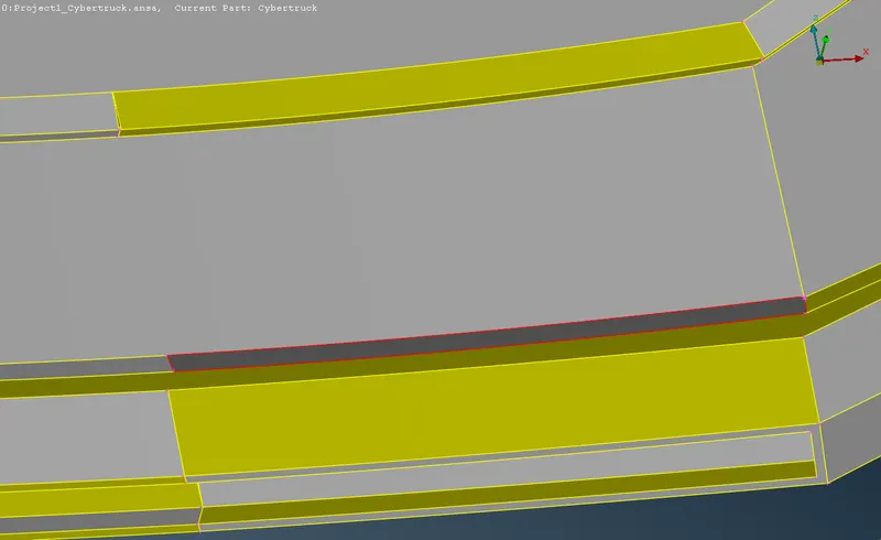
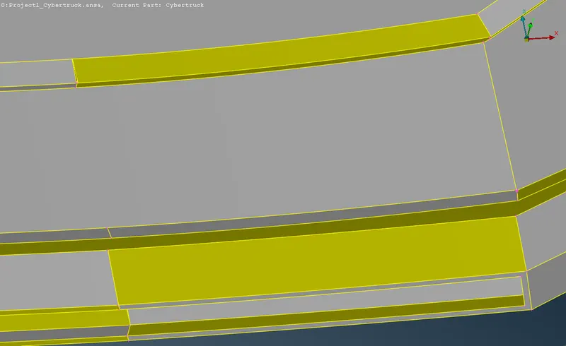
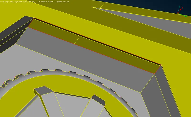
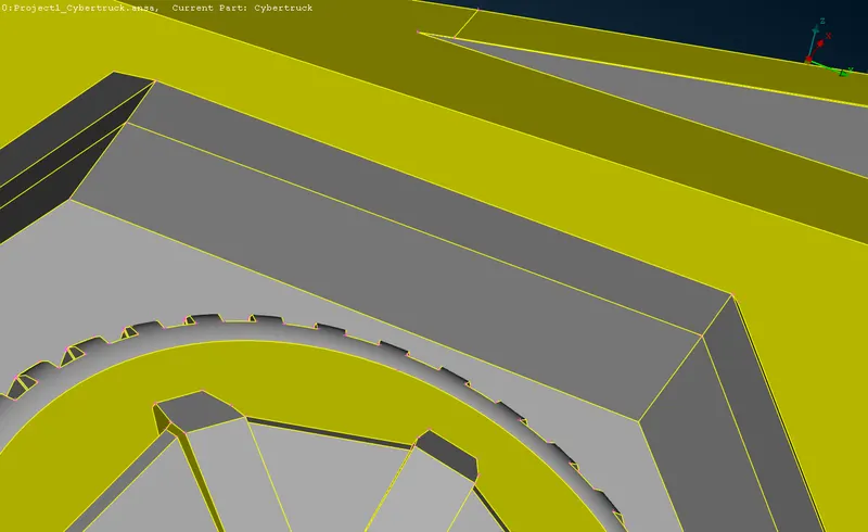
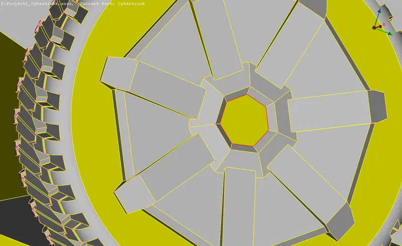
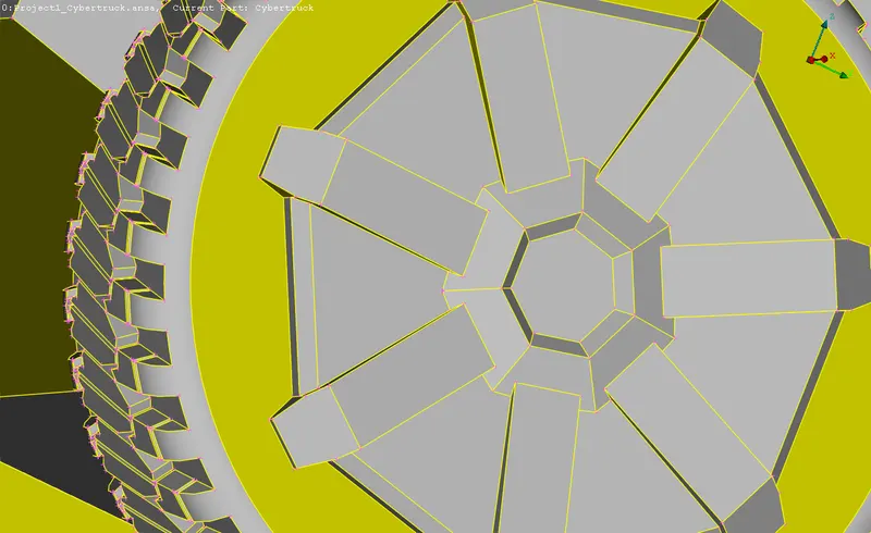
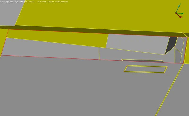
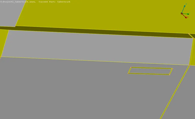
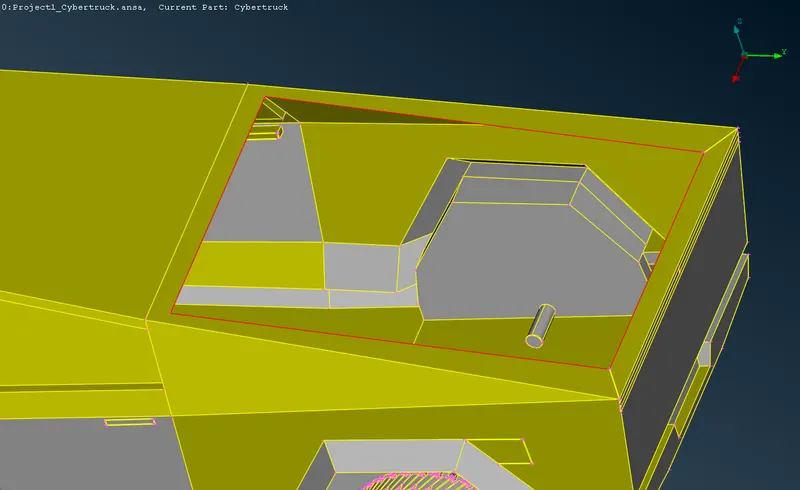
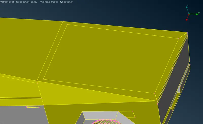
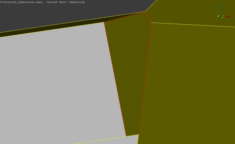
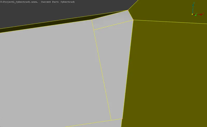
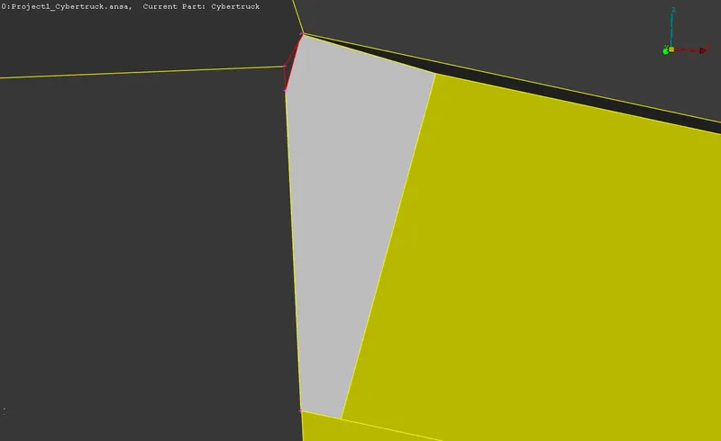
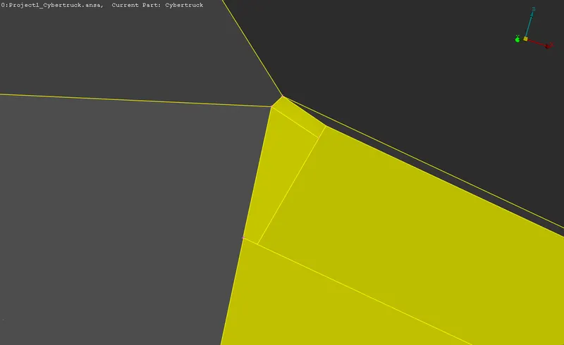
The topology cleanup is defined into types of cons and surfaces. The single cons, triple cons are resolved, followed by the identification of critical surfaces. The surfaces before and after optimization is portrayed in the below table.
3.1.1 Resolving single cons and surfaces
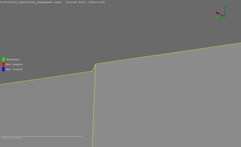
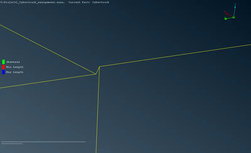
These single cons if unresolved would result in errors during surface meshing, hence it is necessary to resolve them. A variety of tools in the Topo deck is used to resolve these cons and surfaces.
| BEFORE OPTIMISATION | AFTER OPTIMISATION |
 |
 |
 |
 |
 |
 |
 |
 |
 |
 |
 |
 |
 |
 |
 |
 |
 |
 |
 |
 |
3.1.2 Resolving critical surfaces
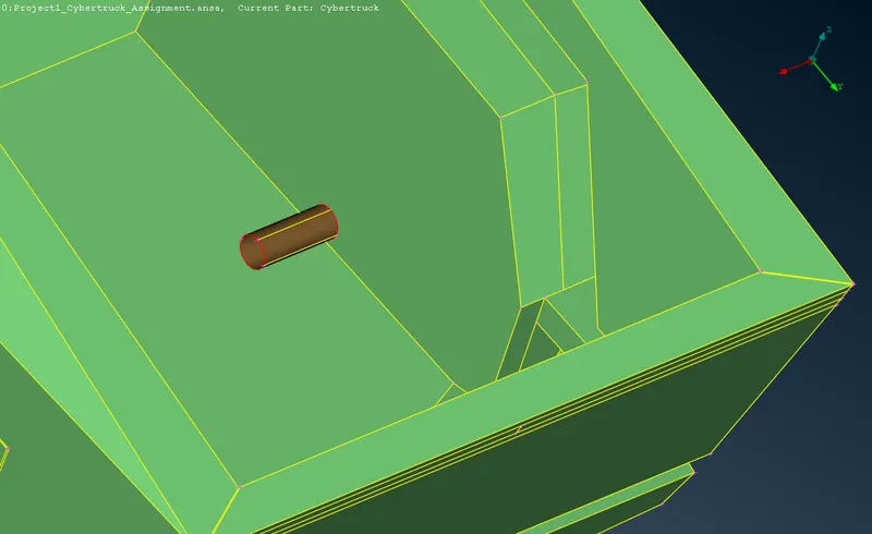
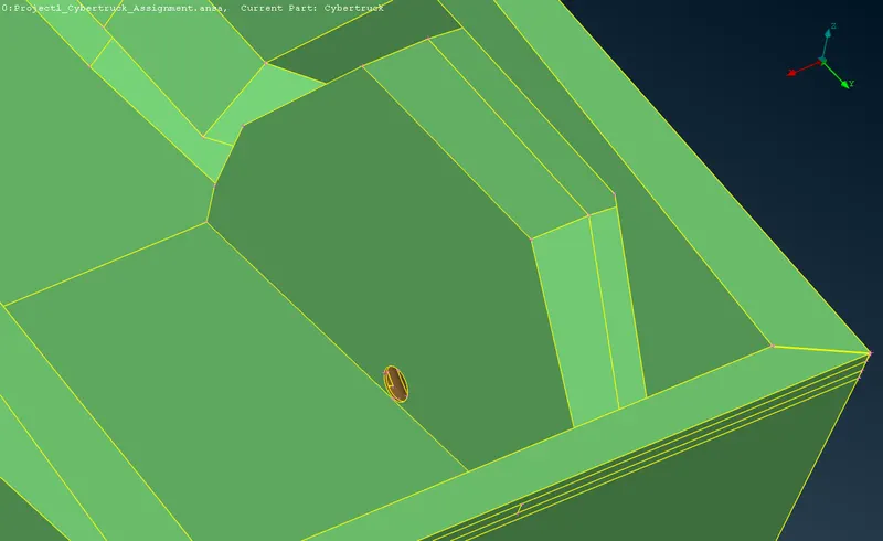
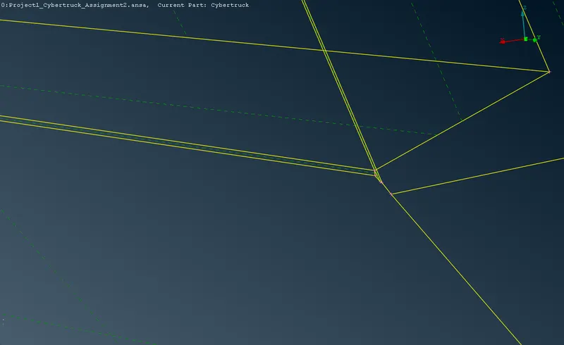
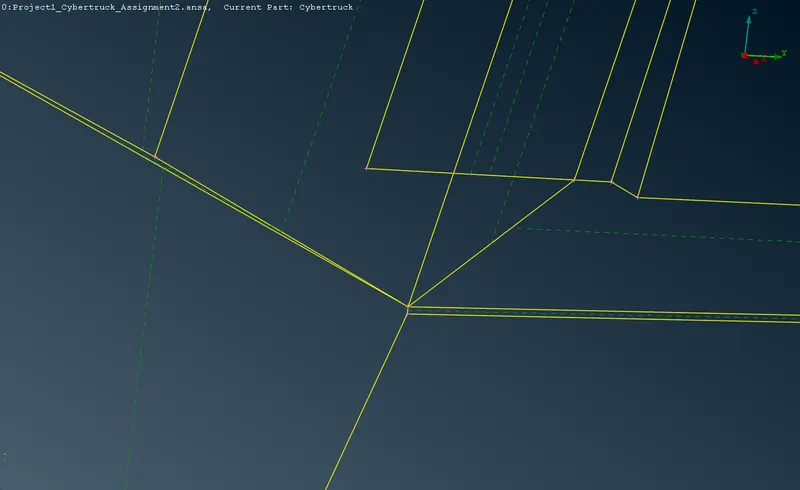
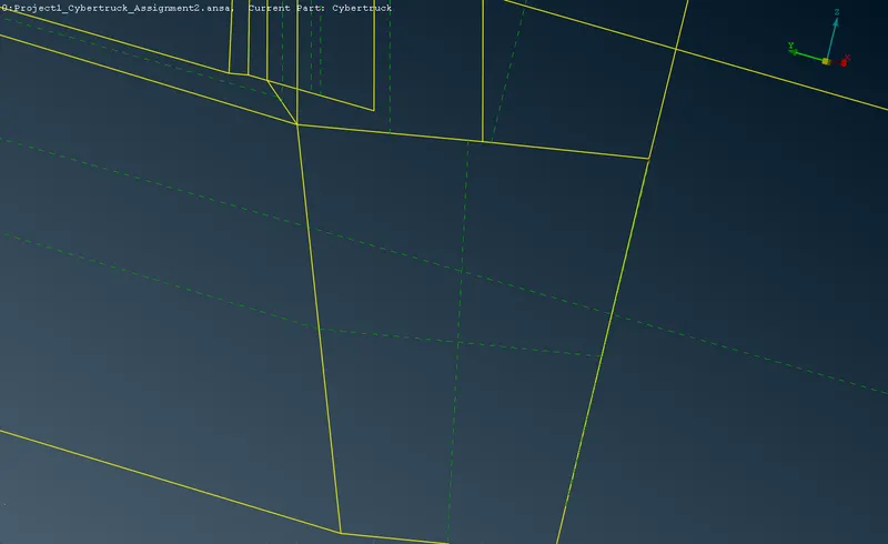
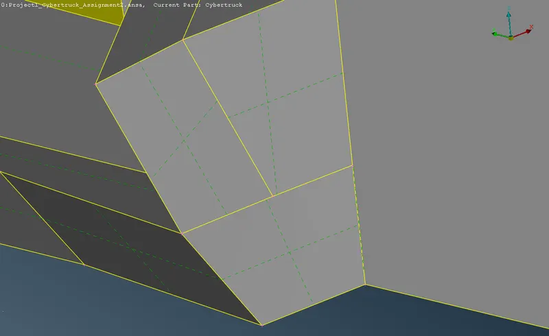
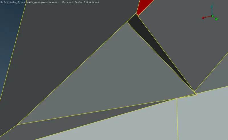
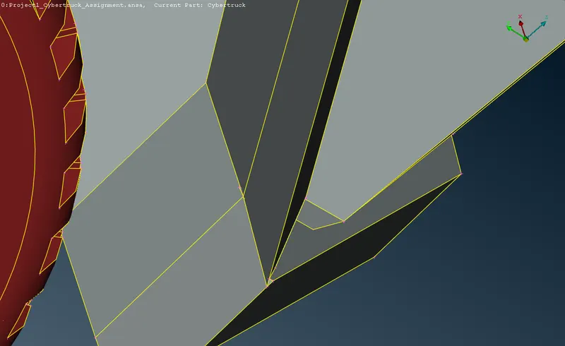
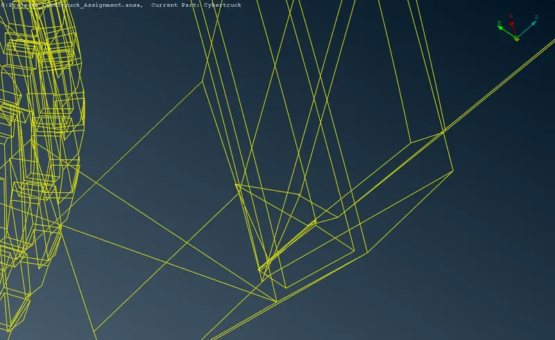
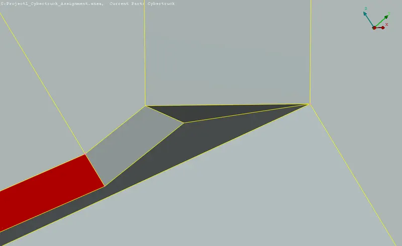
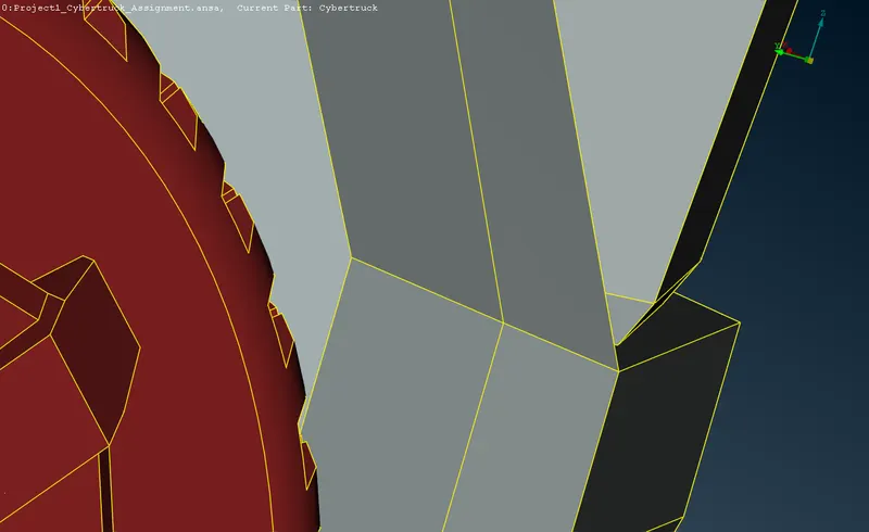
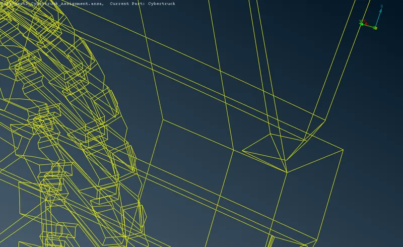
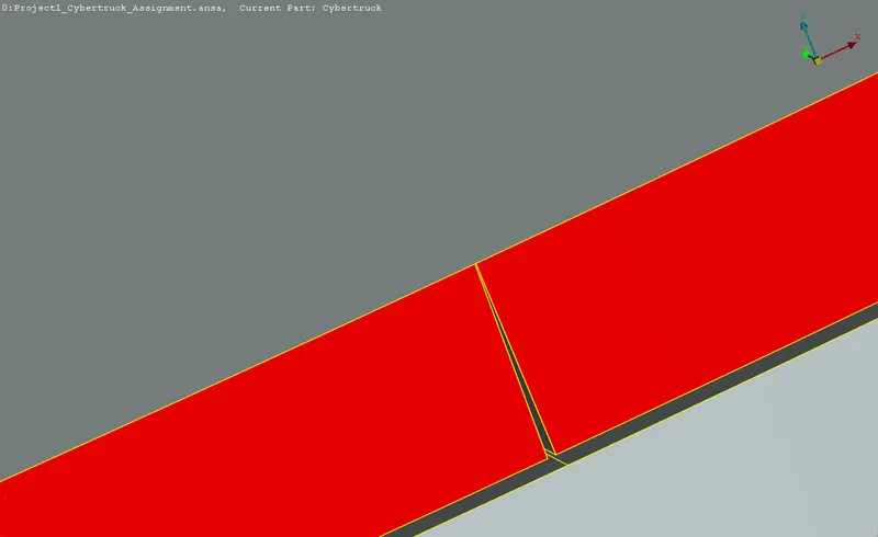
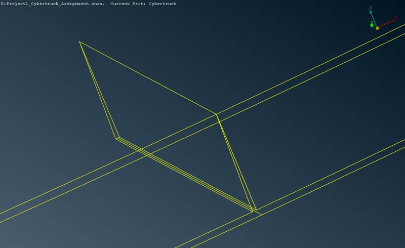
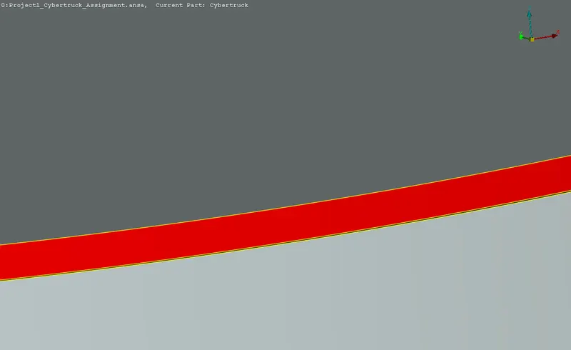
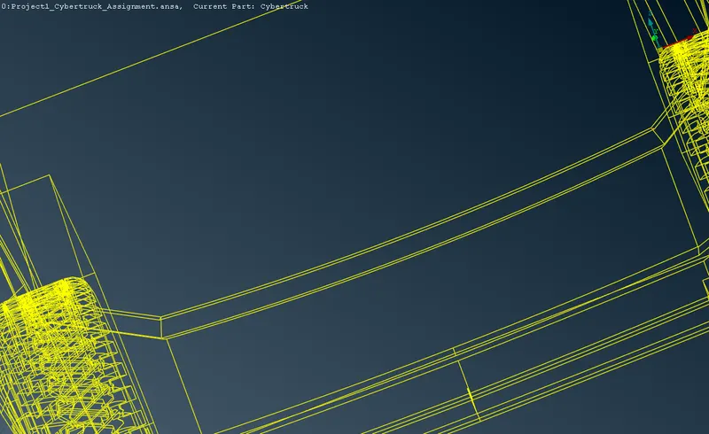
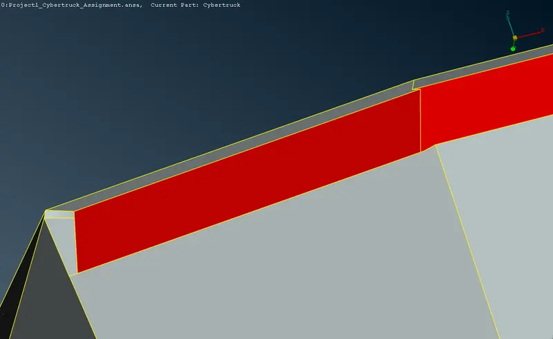
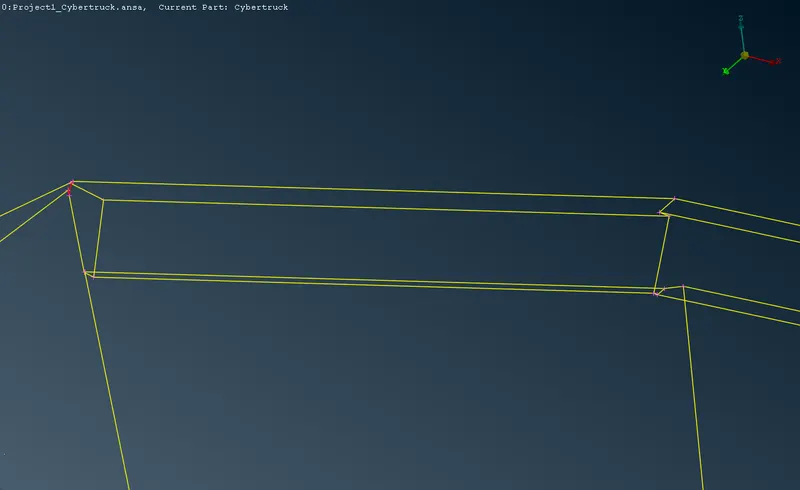
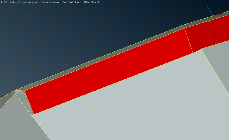
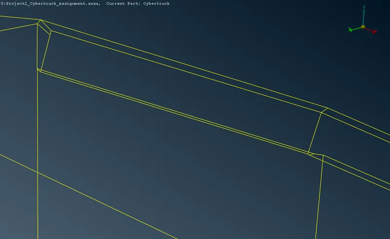
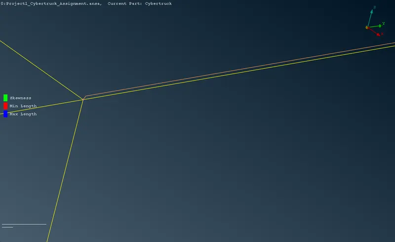
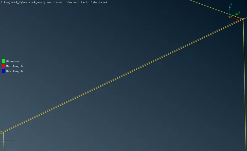
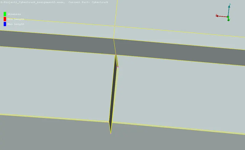
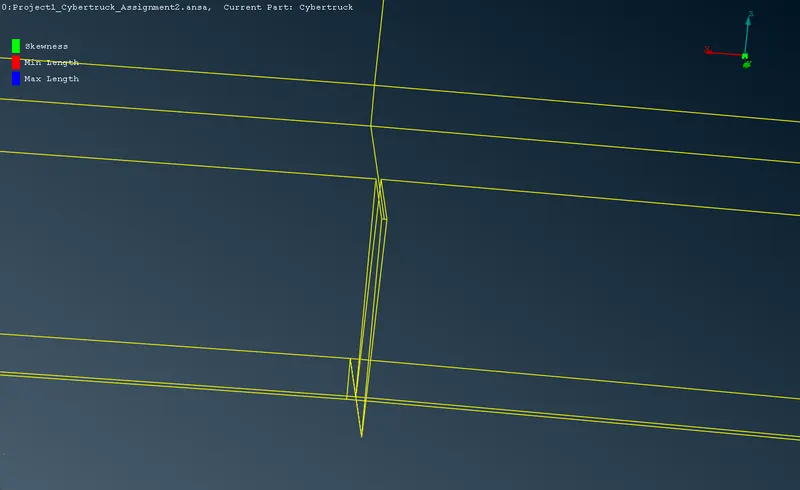
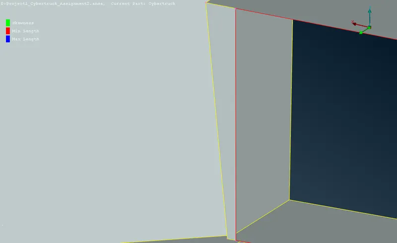
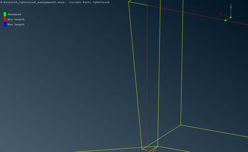
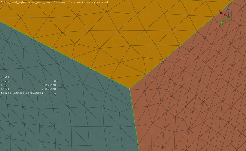
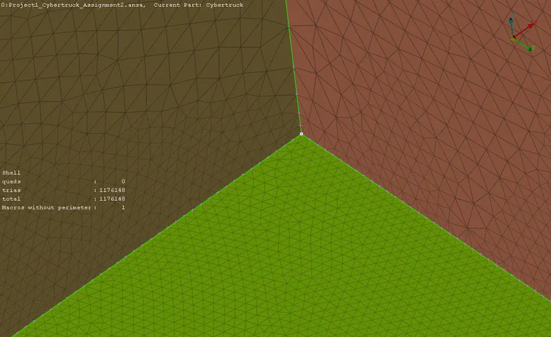
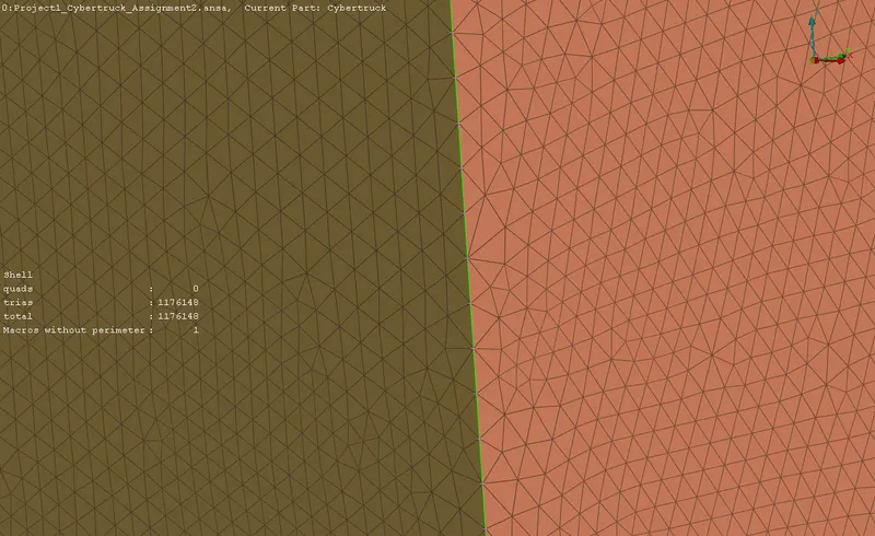
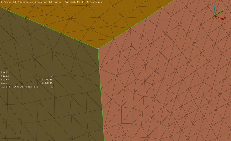
These critical surfaces would result in error during surface and volumetric meshing. The surfaces adjoining the triple cons would create a duplicate volume in volumetric meshing, hence they are resolved. Optimisation is done in a way that the result is a single volume to be meshed.
| Before optimization | After optimization |
 |
 |
|
|
|
|
|
|
|
|
|
|
|
|
|
|
|
|
|
|
  |
  |
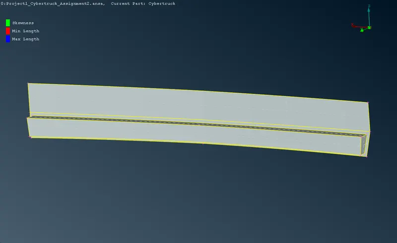
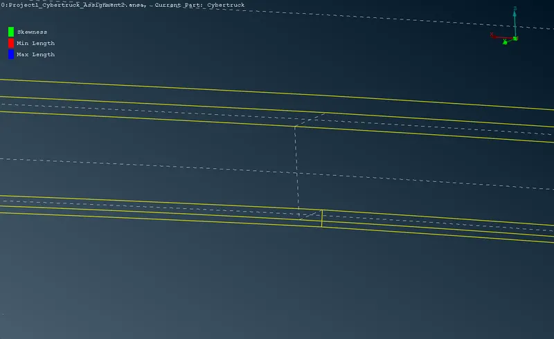
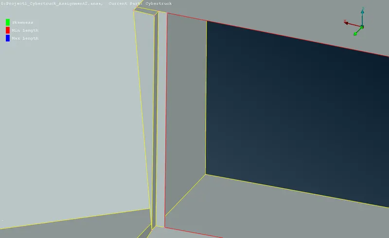
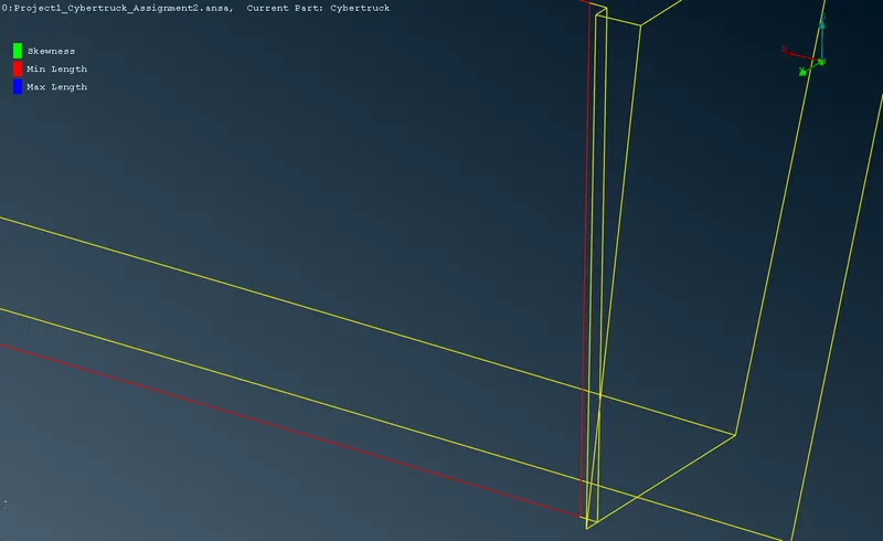
3.3 Assigning PIDs for the truck shell
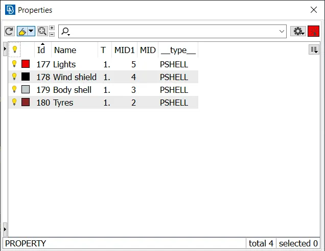
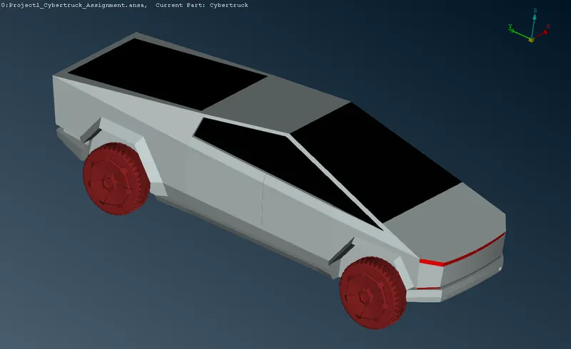
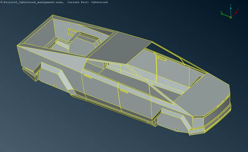
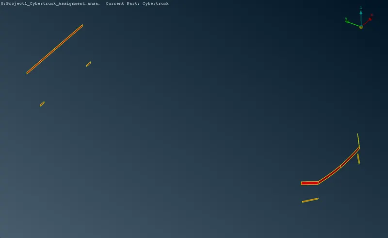
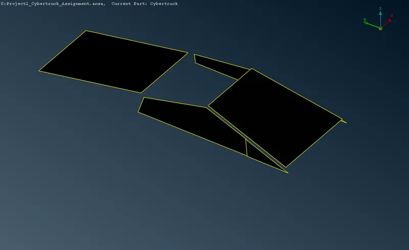
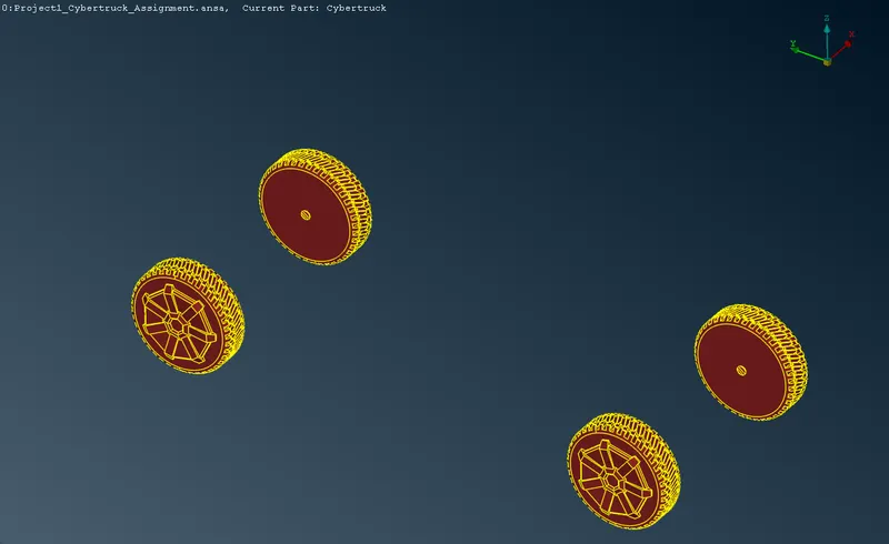
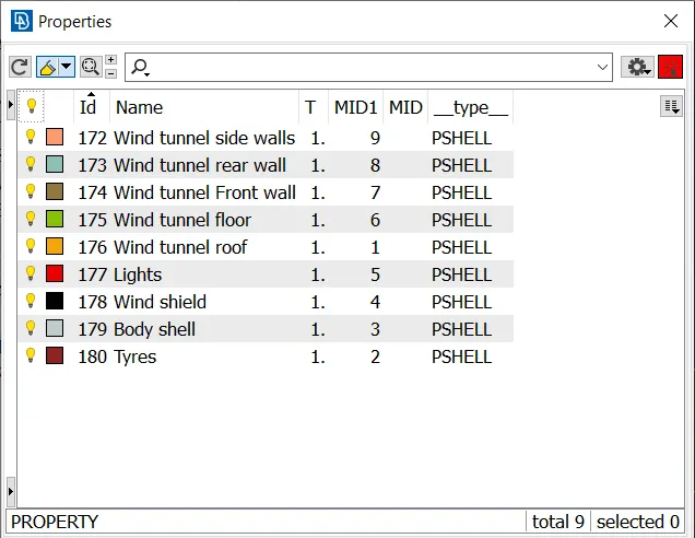
For the truck body alone, four different PIDs are defined for the body shell. wind shield, tyres and lights separatively. The PIDs can be visualized from the color coding defined.
3.4 Geometry check
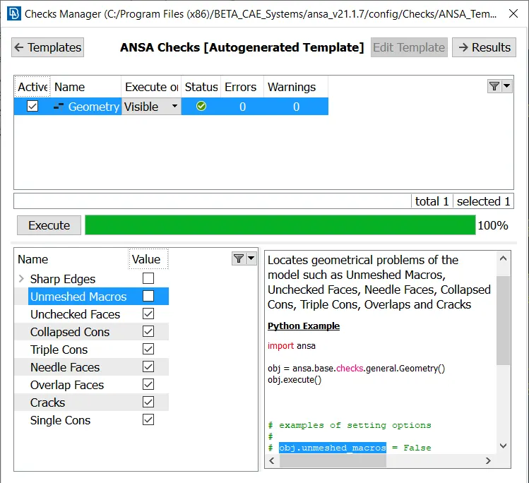
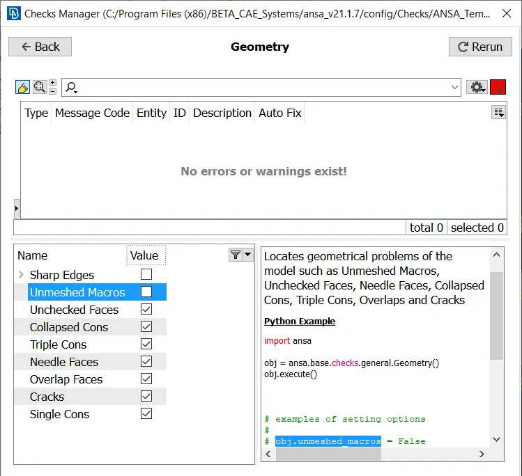
Checks manager > Geometry is an auto-generated tool employed here. After resolving surfaces and cons, the geometry checks is run to identify the anomalies in the model. It is observed that there are no anomalies in the geometry, hence the model can be used for surface meshing.
3.5 Measuring the features
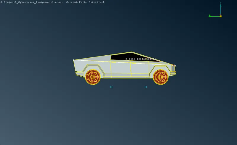
The entities are measured to find out the length of the features, using Measure tool; which is used to determine the mesh length of the PIDs. The entire measurement of the truck body is also measured which is used to build the wind tunnel. The dimensions of the truck body is measured as 6000 X 2000 X 2900 mm.
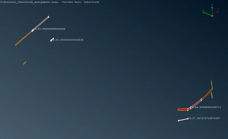
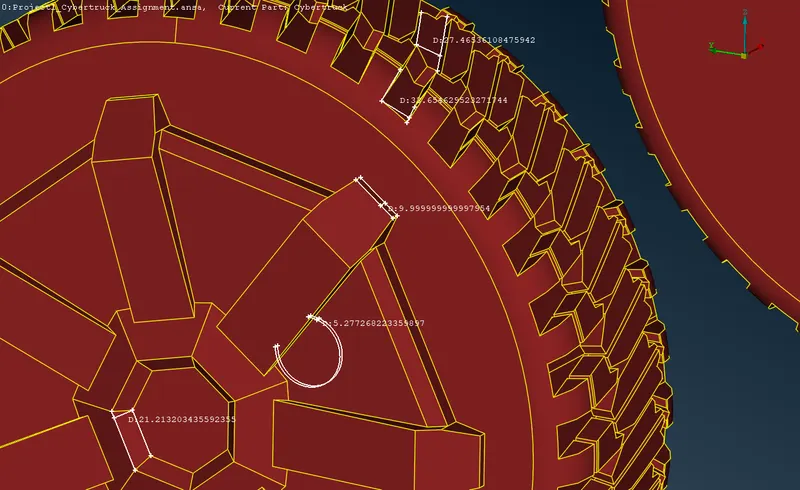
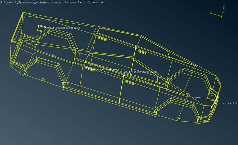
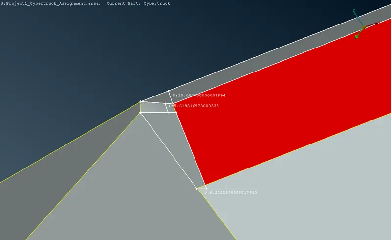
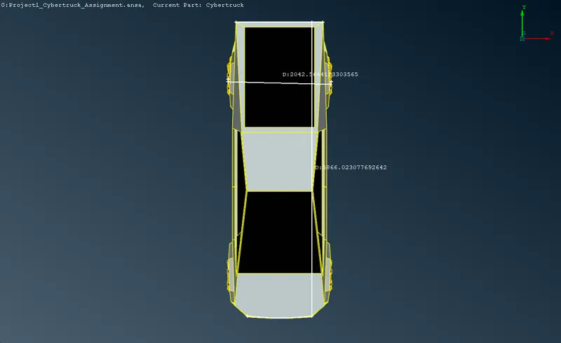
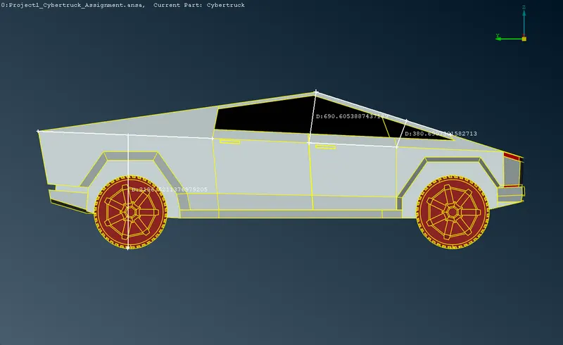
The minimum features of the entities are used to determine the minimum length of the mesh. The dimensions of the truck body is measured as 6000 X 2000 X 2900 mm.
3.6 Surface meshing of truck shell
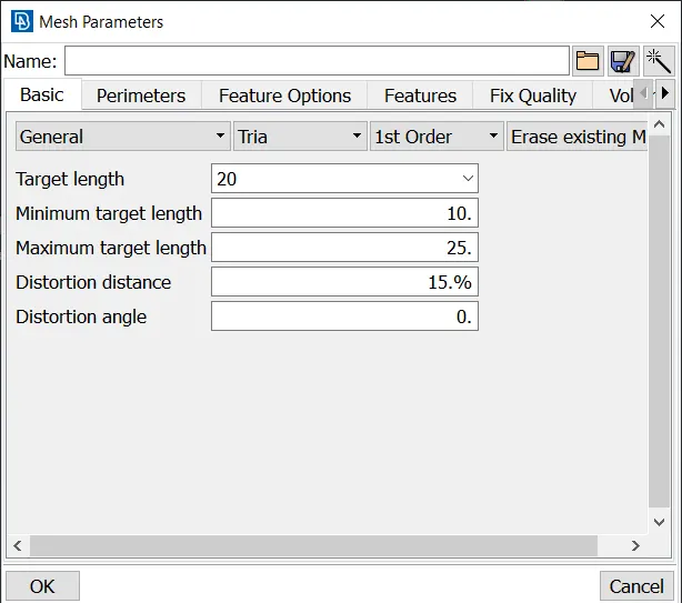
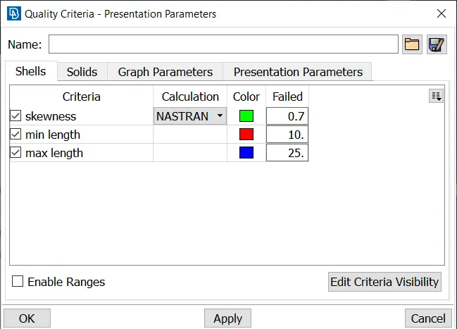
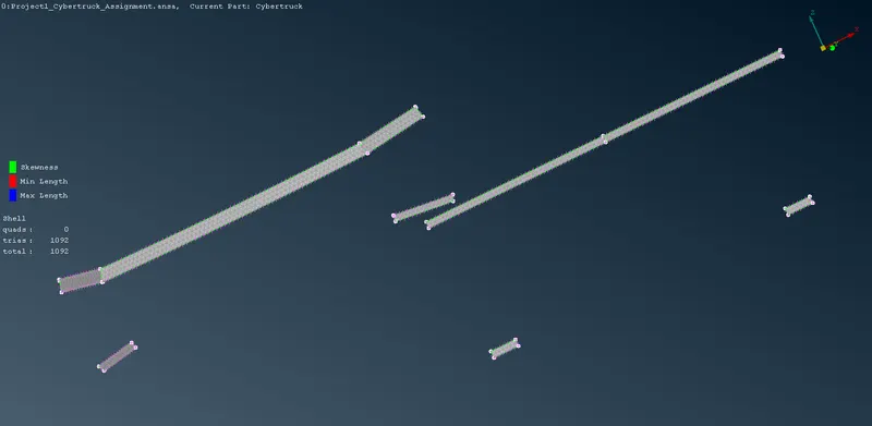
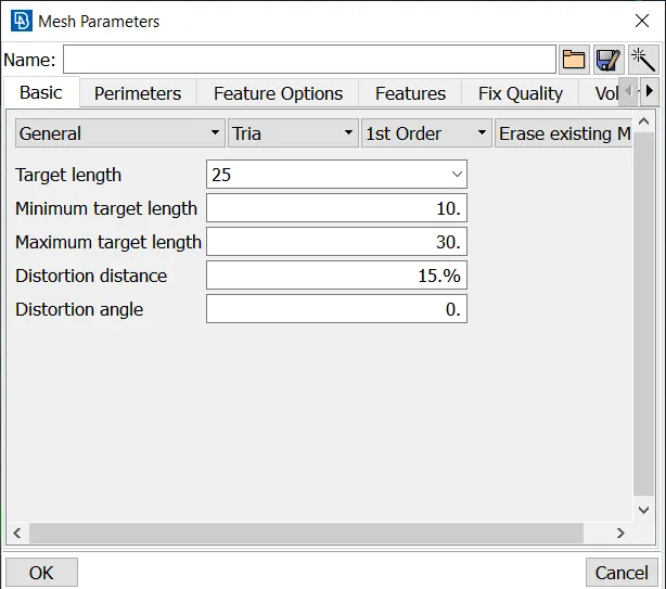
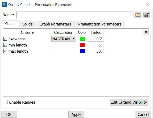
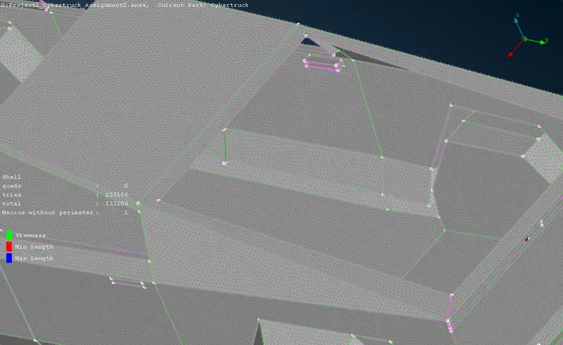
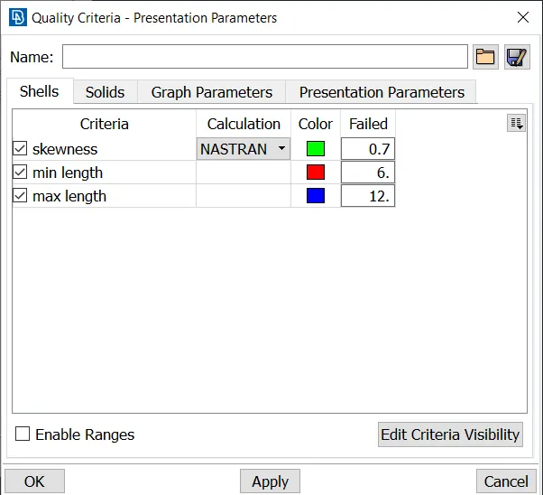
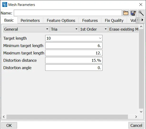
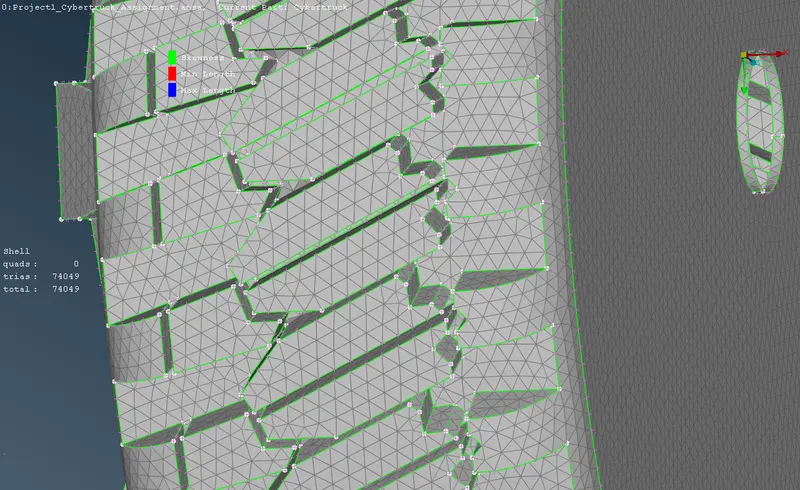
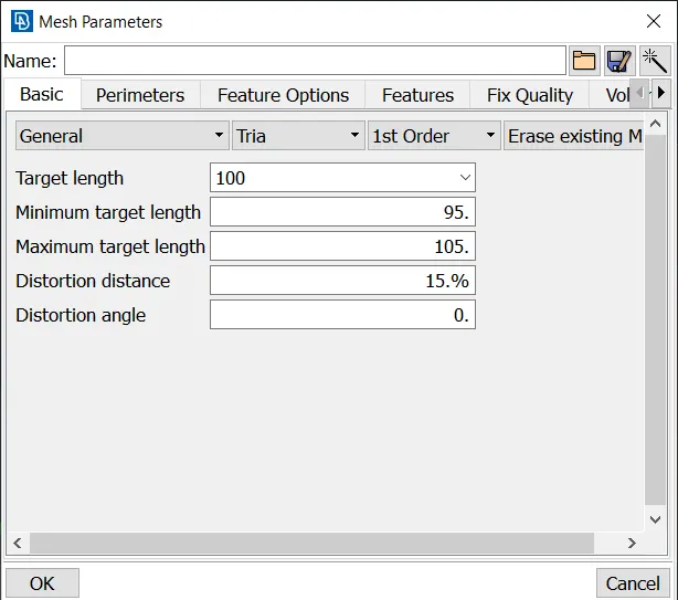
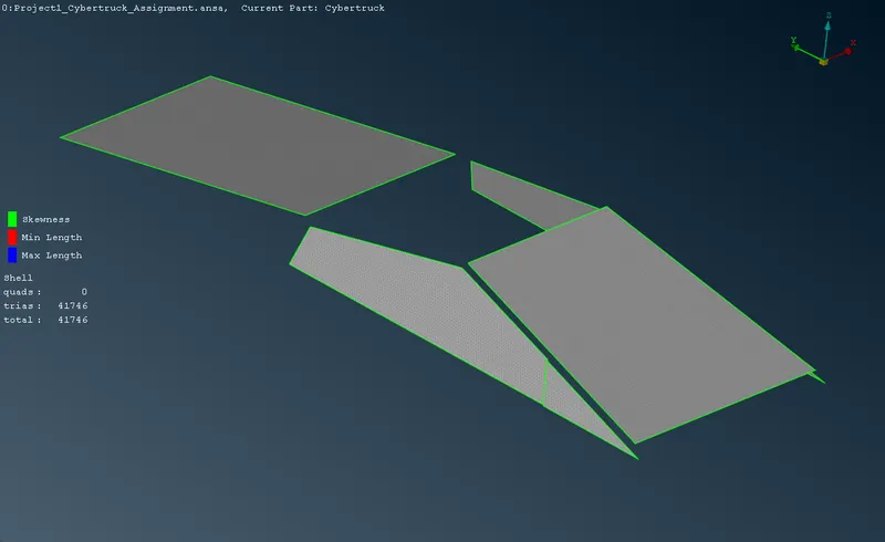
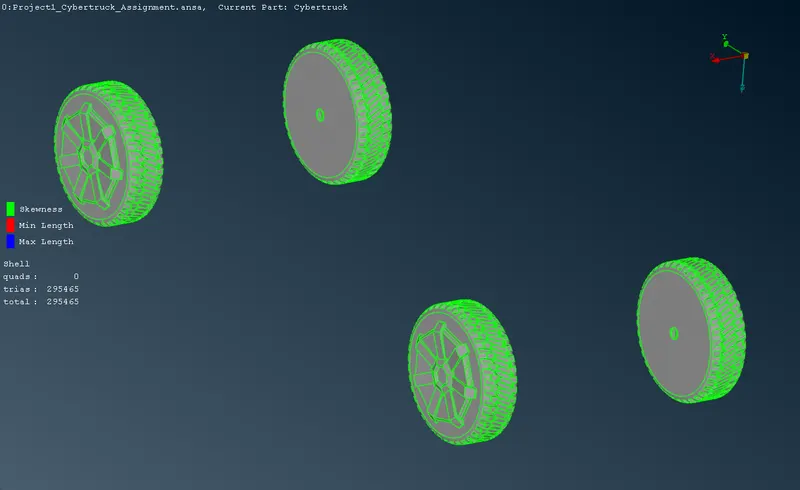
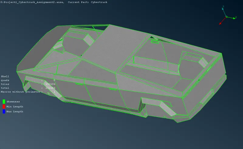
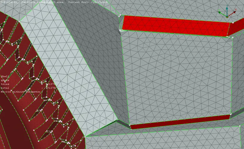
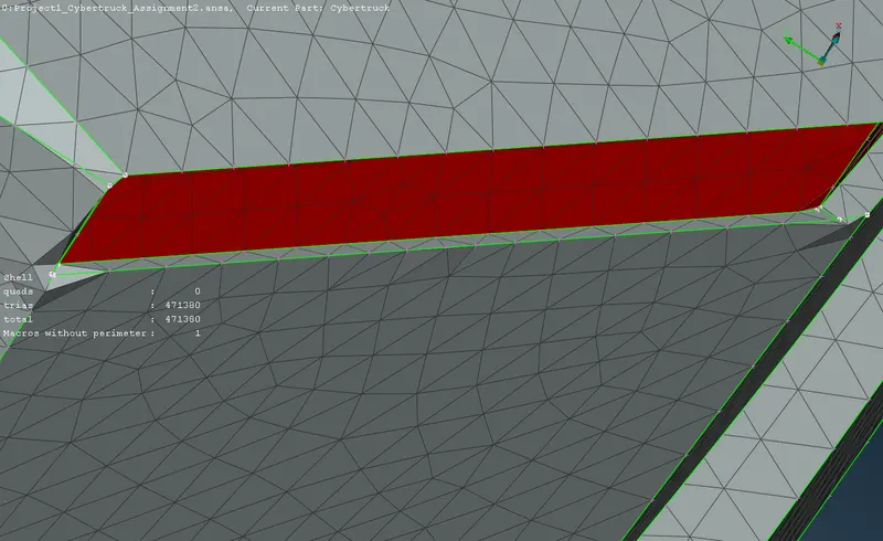
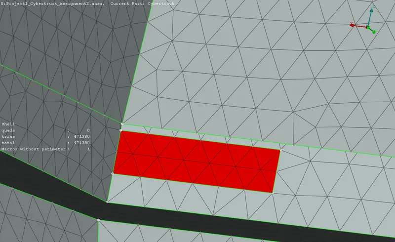
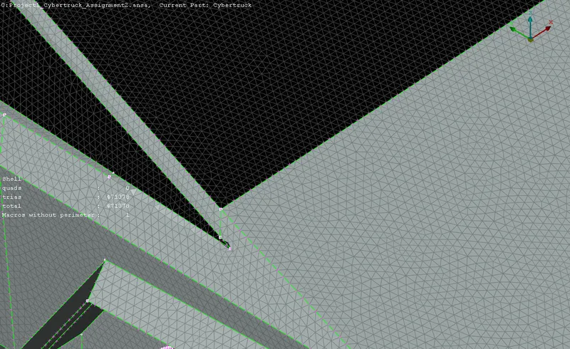
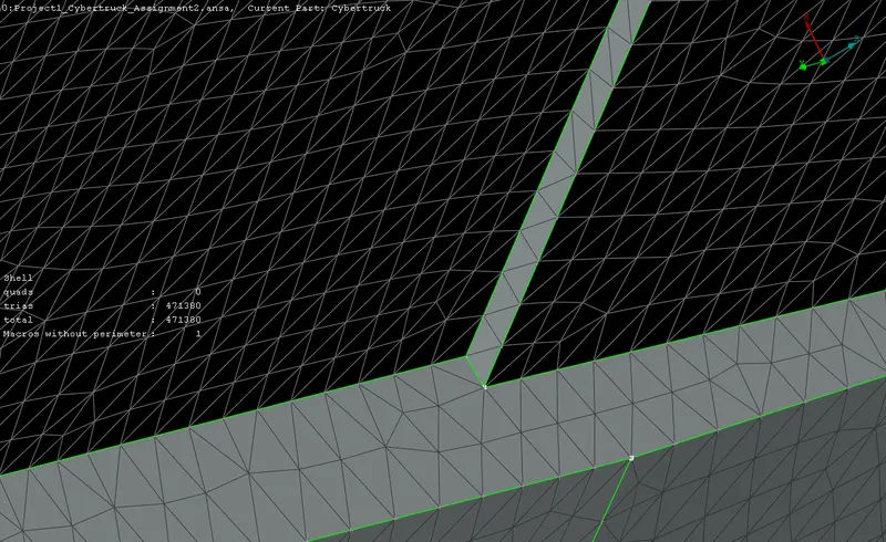
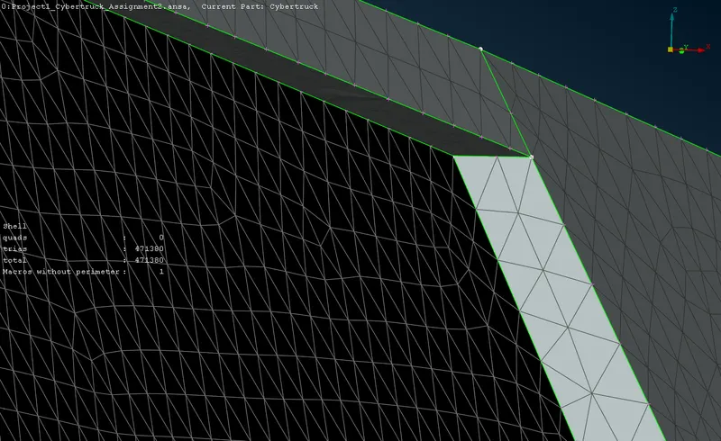
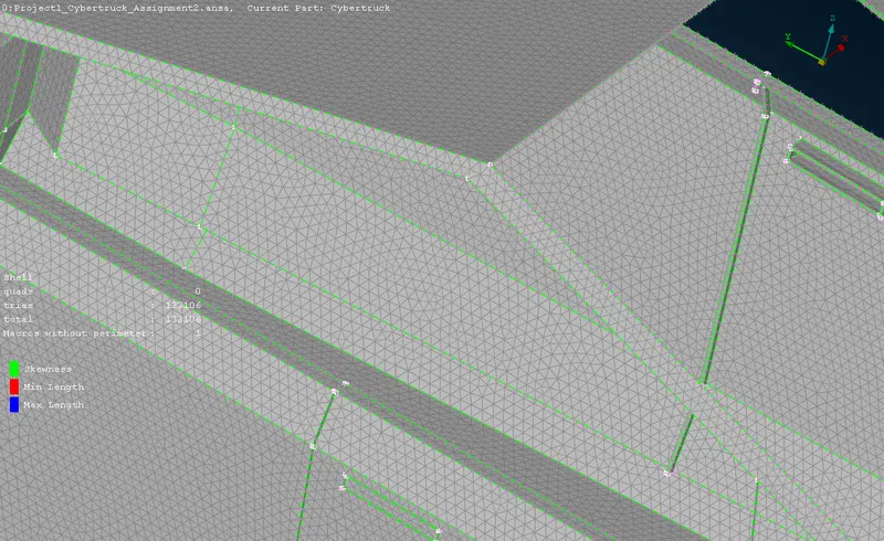
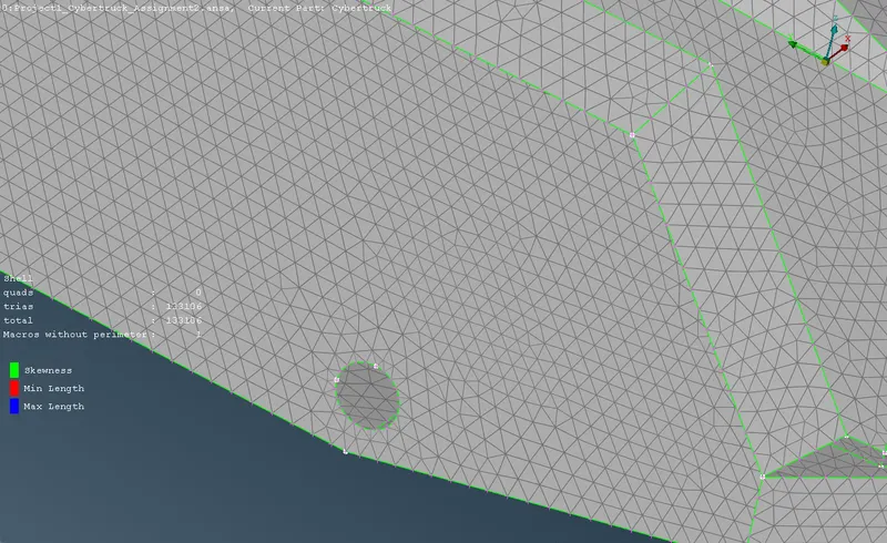
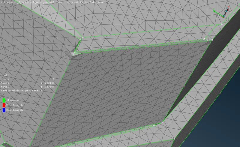
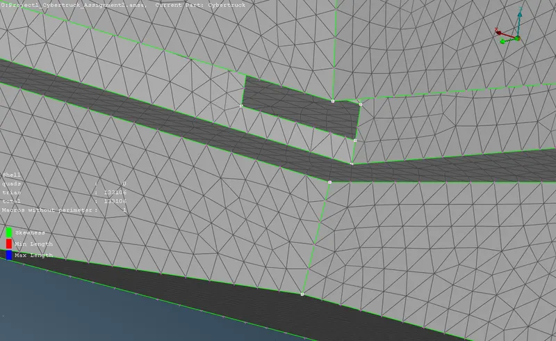
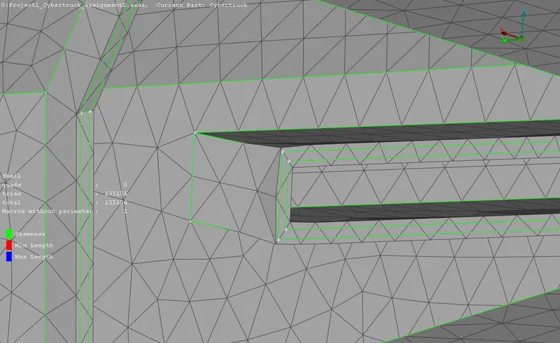
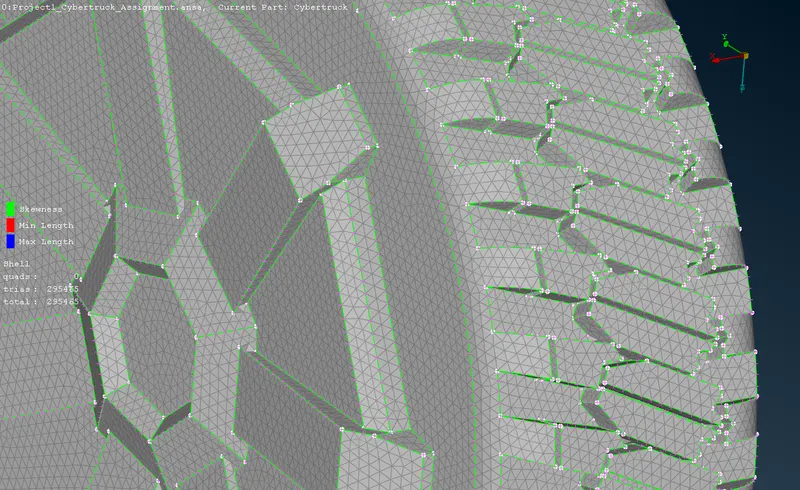
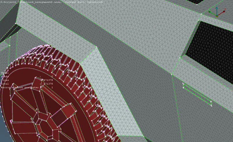
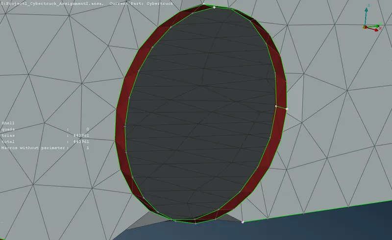
Each PIDs are meshed individually by defining the min and max lengths from the measurements. The quality criteria is also defined and visualized. The off elements are resolved by using the tools in the mesh deck. Tria element type is used to mesh the surfaces. Skewness, min and max length are used as the quality criteria. Perimeter > Length is used to define the perimeters and Spot Mesh tool is used to mesh.
3.6.1 Surface meshing of PID 1 Lights
3.6.2 Surface meshing of PID 2 Wind shield
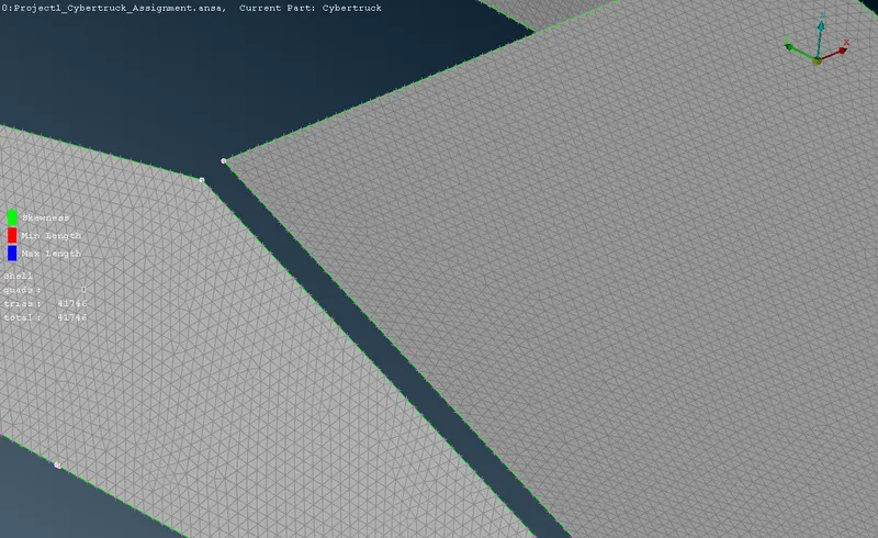
3.6.2 Surface meshing of PID 3 Body shell
3.6.4 Surface meshing of PID 4 Tyres
3.7 Quality optimization
The off elements identified are resolved by using the tools in the mesh deck. The quality criteria used is Skewness, min and max length of the tria elements. The elements violating the max size can be split into two smaller elements or the grids can be moved to a optimum position when not on an edge, using Move, Split, Improve, Fix tools.. The elements violation the min length criteria can be conveniently cleared by using the Reconstruct, Reshape, Fix quality, Smooth tools.
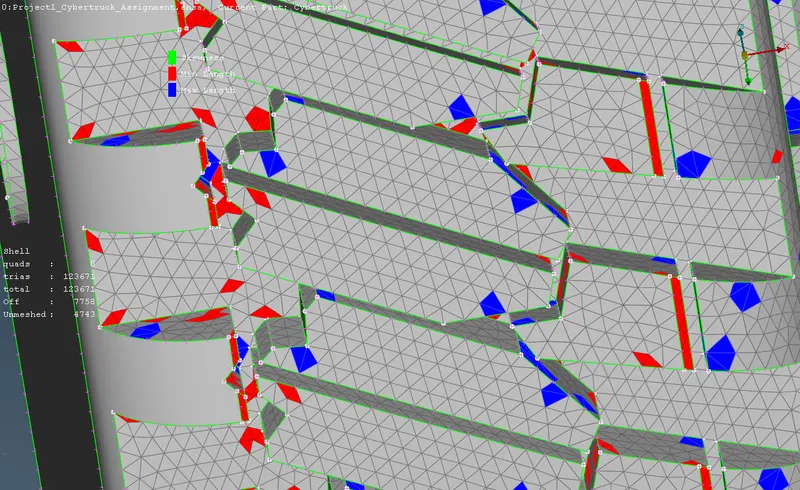
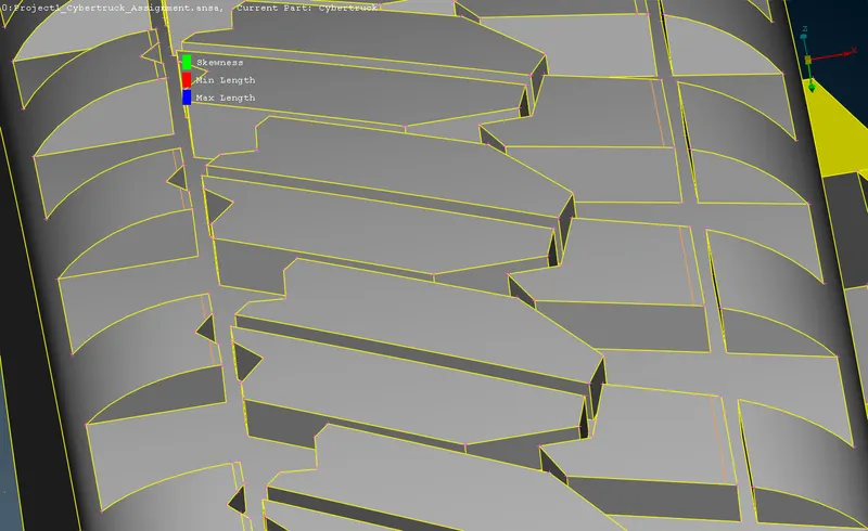
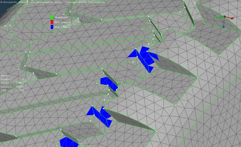
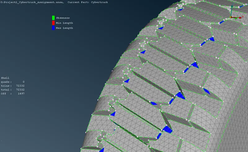
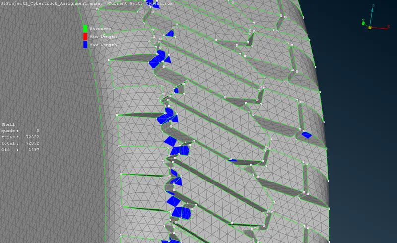
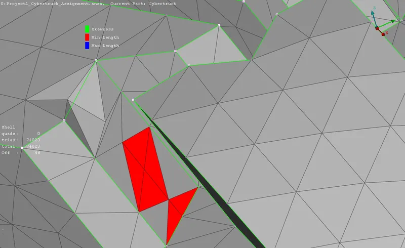
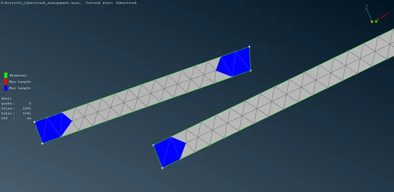
Some elements which cannot be cleared using the auto functions has to be cleared by adjusting the cons and nodes in the topo menu, and the remeshing again. The tyres which has a wide range of minute features is cleared from the topo deck, by using cuts and removing unwanted hotpoints and nodes.
3.8 Pre-surface mesh check
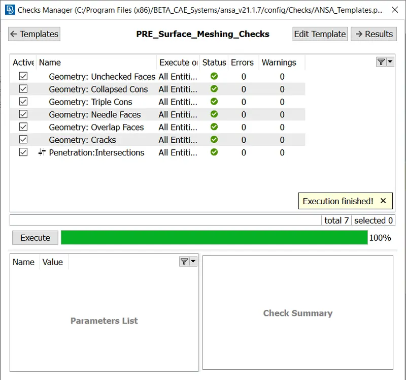
Checks manager > pre-surface mesh checks is run to find out the anomalies in the surface meshed model before going to volumetric meshing. It is observed that there is no anomalies found in the surface meshed model.
3.9 Building a Wind tunnel
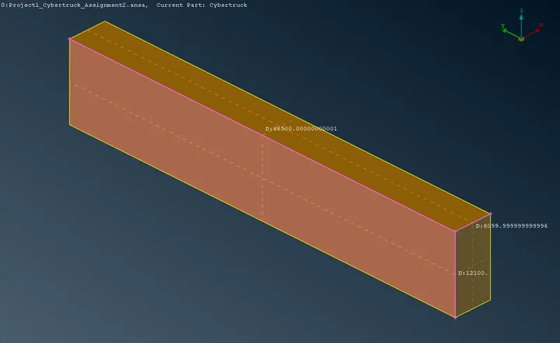
A wind tunnel is built around the truck body to specify the computational domain. The wind tunnel size is determined from the average dimensions of the truck body which is measured previously. A typical wind tunnel should have dimensions of 6x mm in the back, 4x mm in the front, 1x mm in the sides and 3x mm on the top, where x is the dimension of the truck respectively.
Initially points are defined at desired locations. The first point is defined at the bottom centre of the model at (0,0,-500). The front points are defined at -Y 27200. the rear points are defined at +Y 39300. The top points at +Z 12100. The side points at +X 3050 and -X 3050.
Curves are created in between the points. New surfaces are created using the curves defined and is named as roof, floor, front wall, rear wall, side walls respectively.
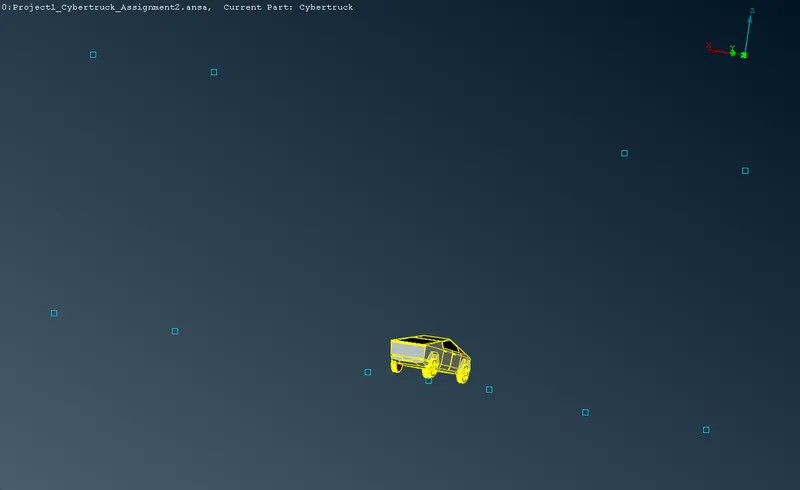
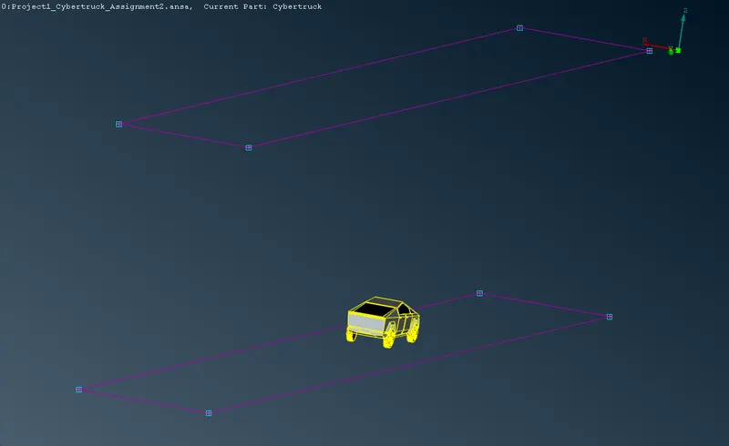
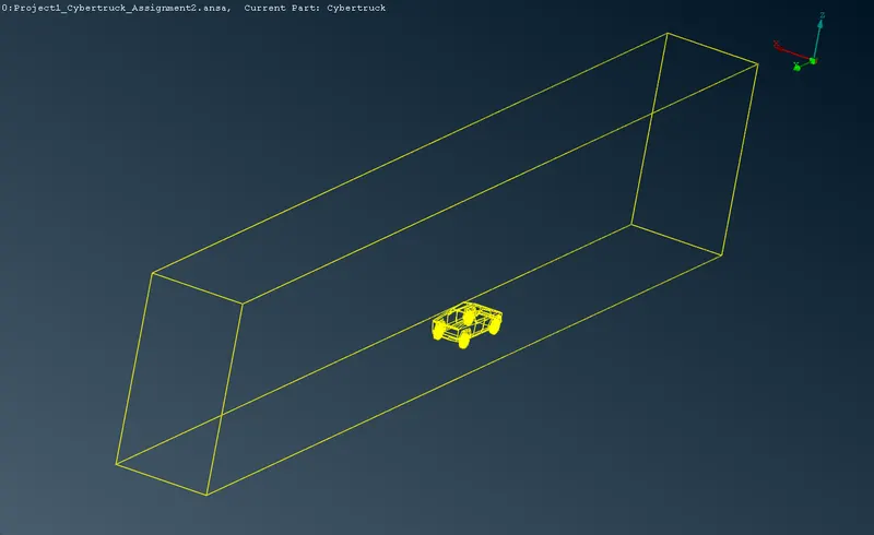
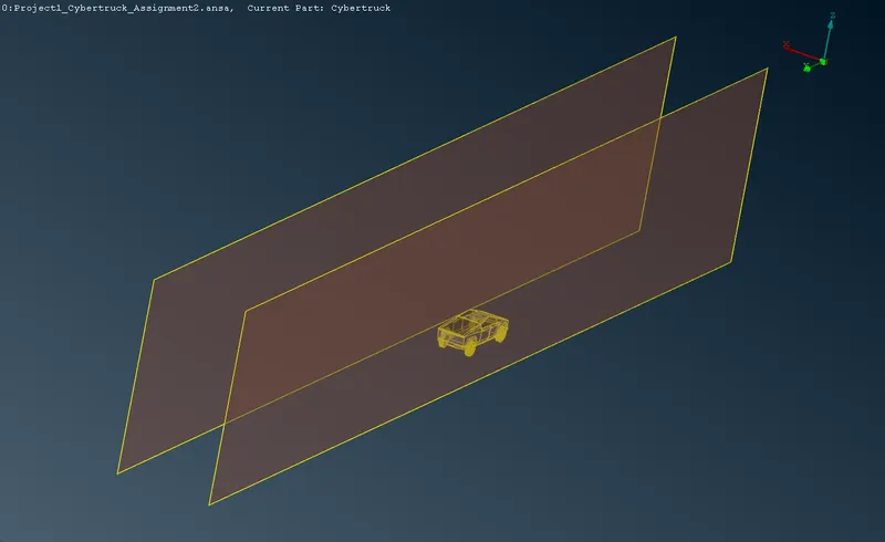
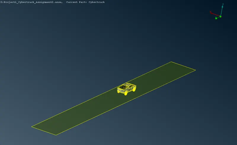
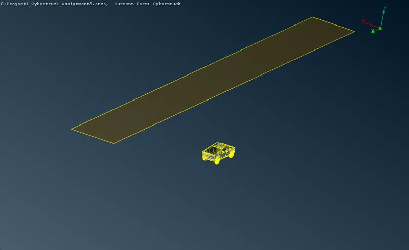
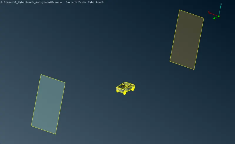
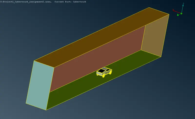
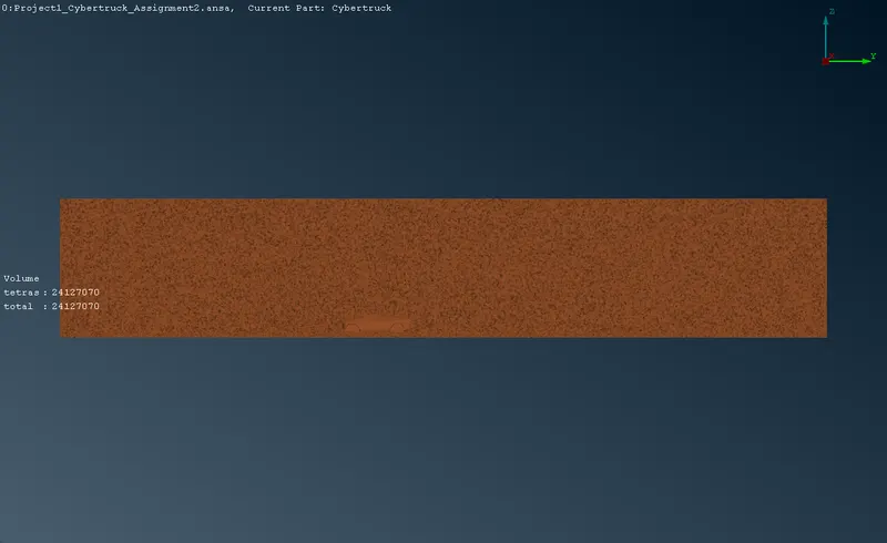
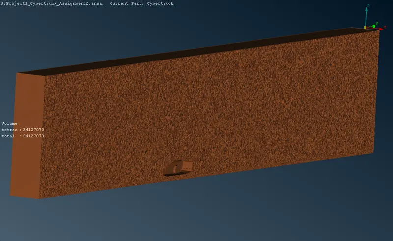
The PIDs are defined as per the orientation of the wind tunnel surfaces which would enable defining variable mesh sizes for the surfaces. 5 different PIDs are defined for the wind tunnel surfaces. A wind tunnel of dimension 66500 X 6100 X 12100 mm is designed around the truck body to define the computing domain.
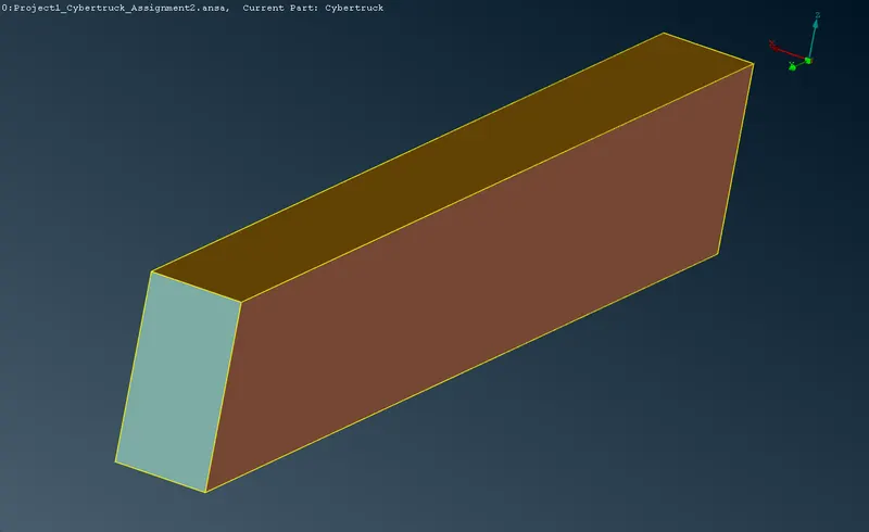
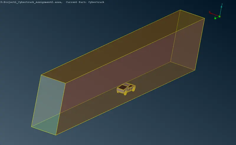
3.10 Surface meshing of the wind tunnel
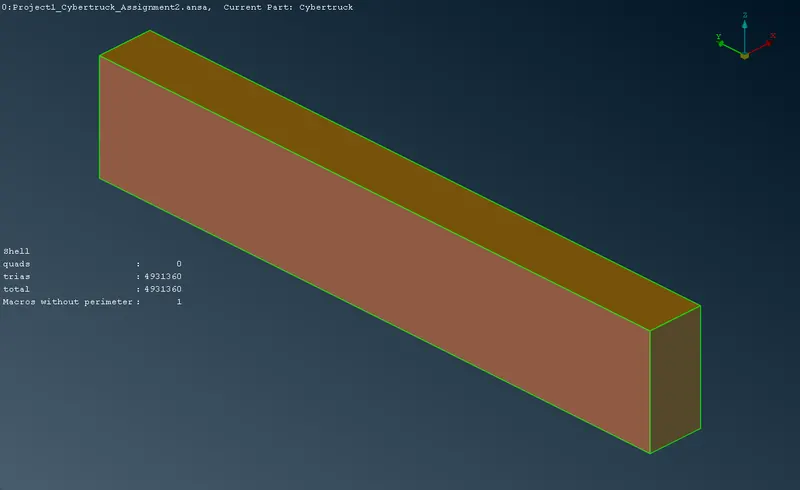
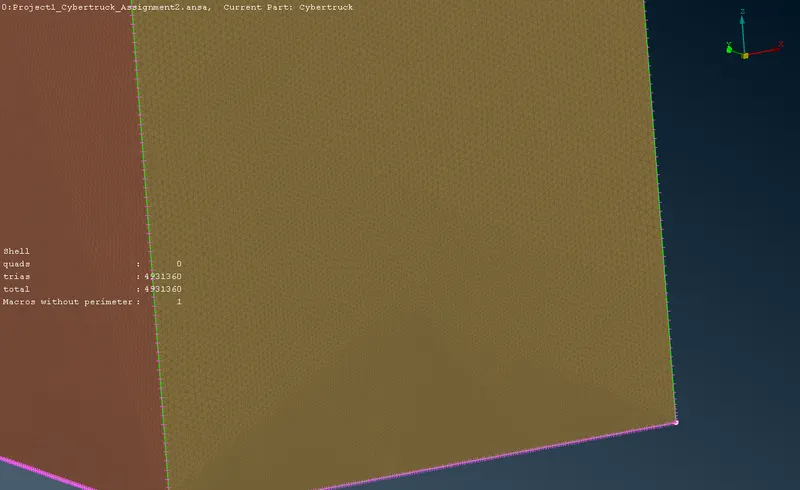
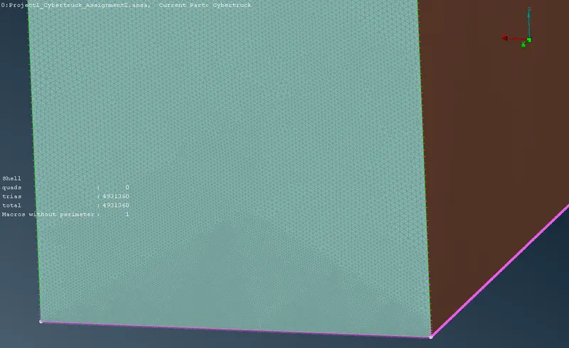
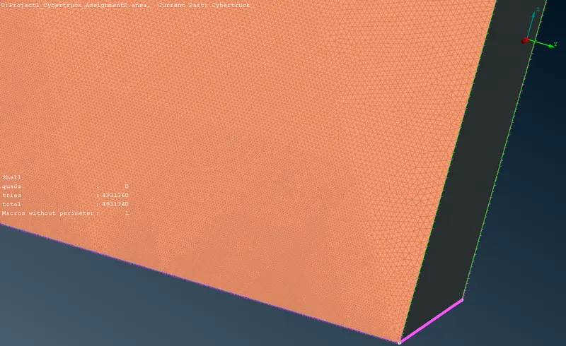
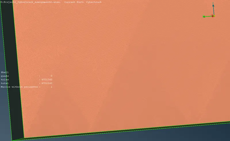
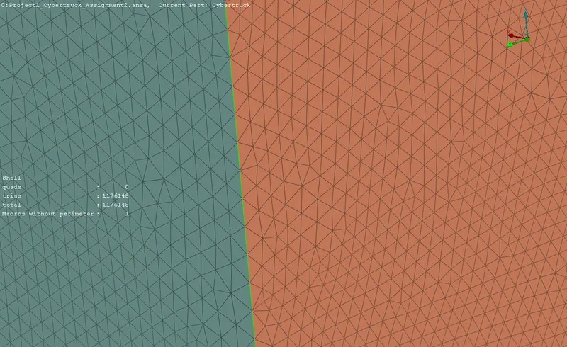
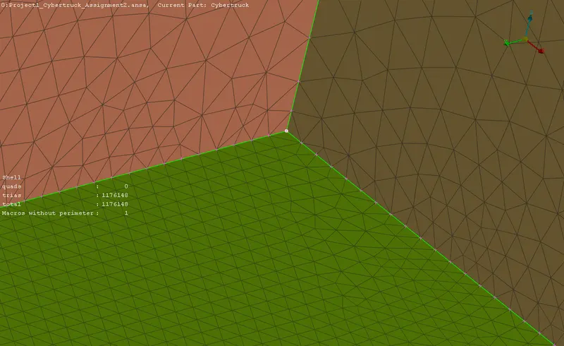
The wind tunnel is surface meshed using Tria elements with constant length for the roof and floor, while the front, rear and side walls are given a variable length to optimize the computing efficiency.
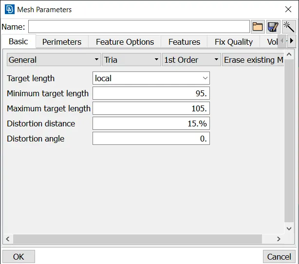
Spacing > Geometric tool is used to define the varying perimeter length of the edges from 20 to 100 with factor of 1.2.
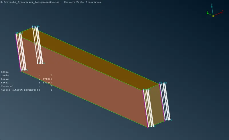
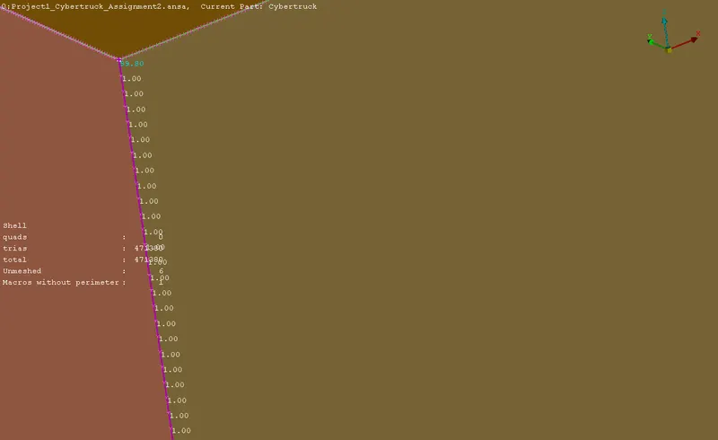
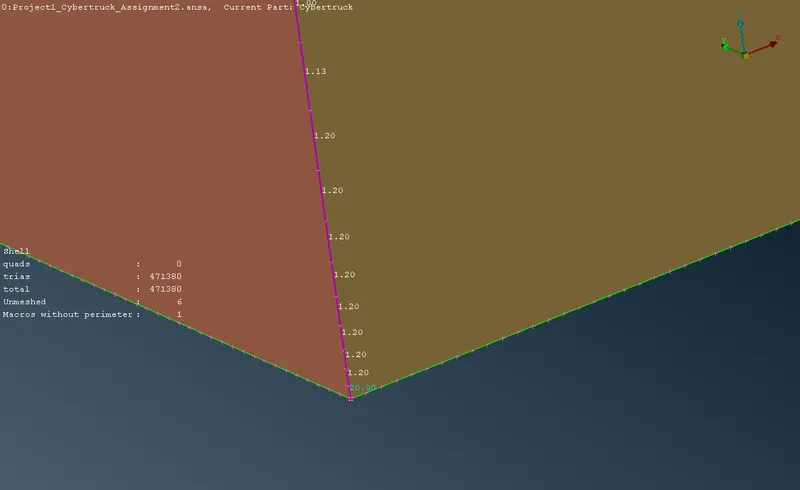
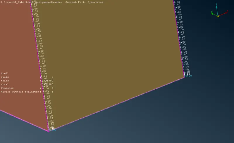
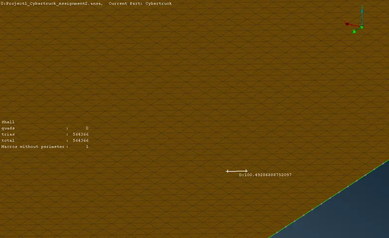
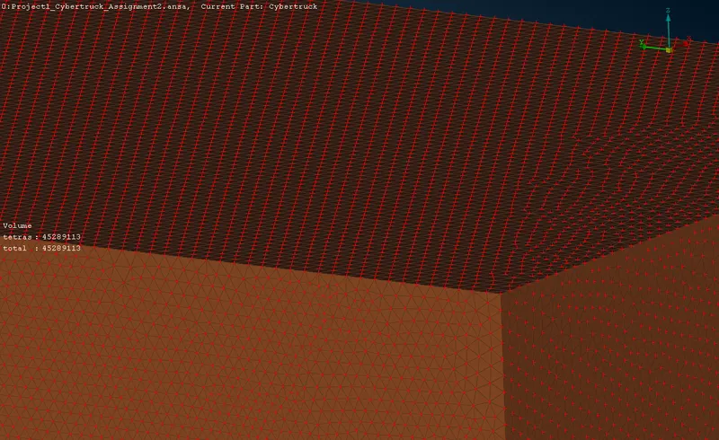
The roof of the tunnel is meshed with tria elements with a constant mesh size of 100mm.
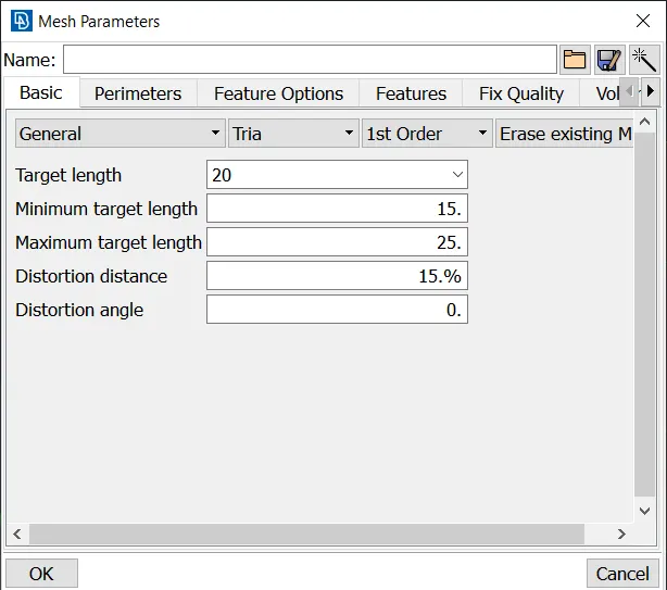
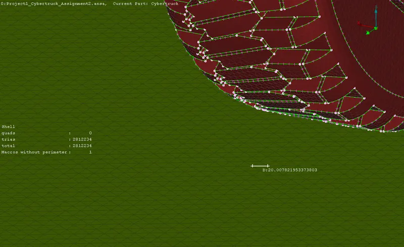
The floor of the tunnel is meshed with tria elements of constant length of 20mm.
The walls have a varying average elements size with tria elements in the surface mesh.
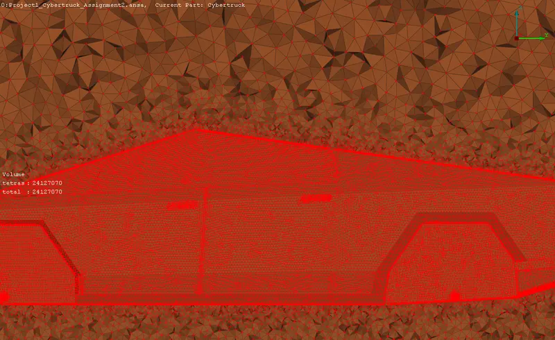
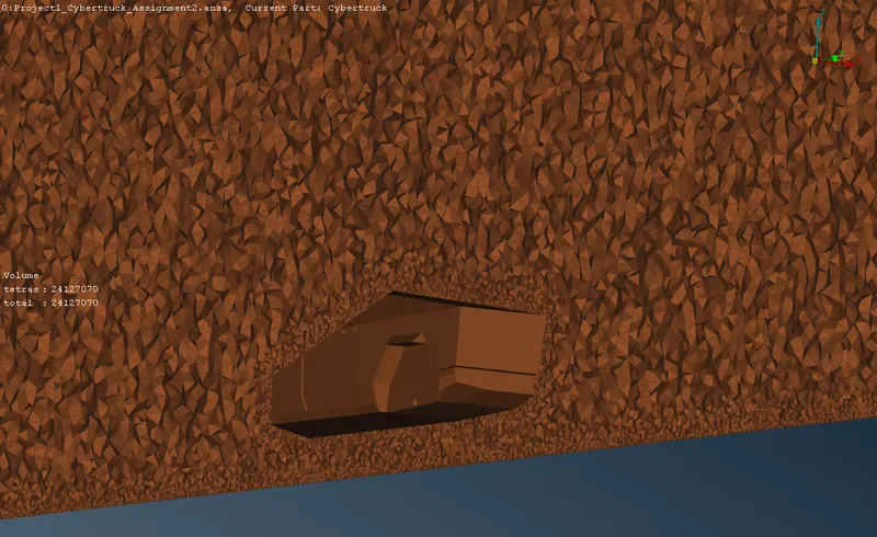
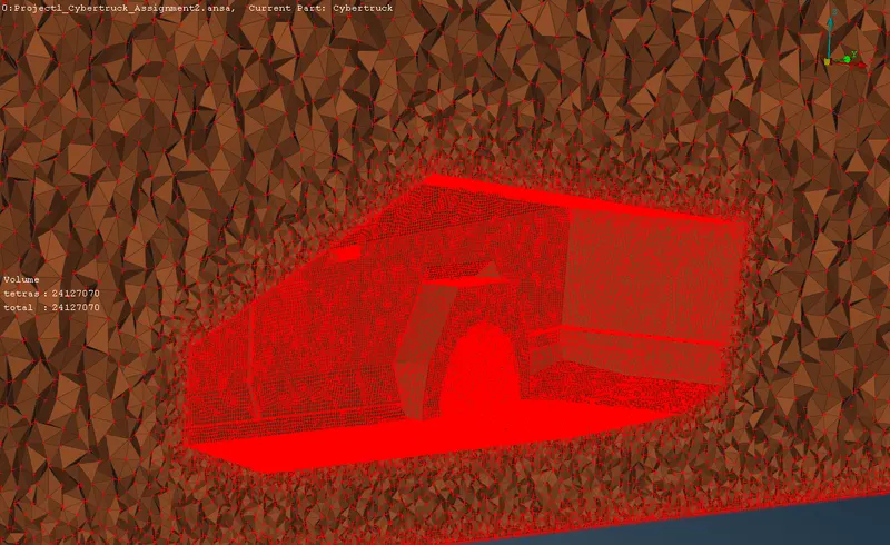
3.11 Volumetric meshing
3.11.1 Defining the volumes
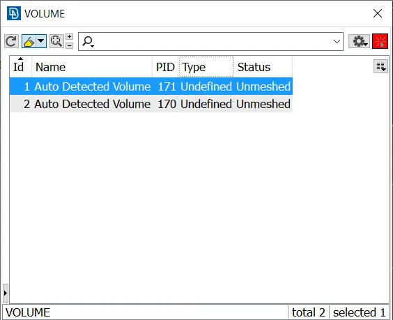
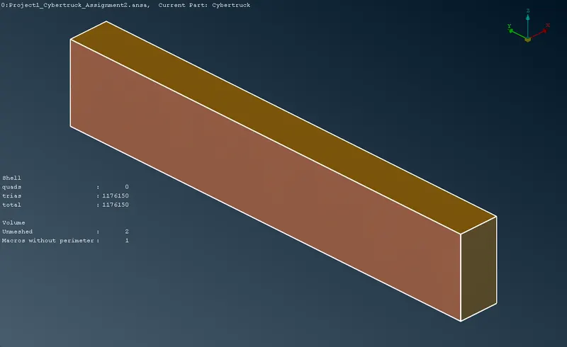
Volumes > Auto detect detected two volumes, in which one is the truck body and the other is the volume between the truck body and the wind tunnel. The truck body volume is deleted and the second volume is kept for meshing.
3.11.2 Meshing the volumes
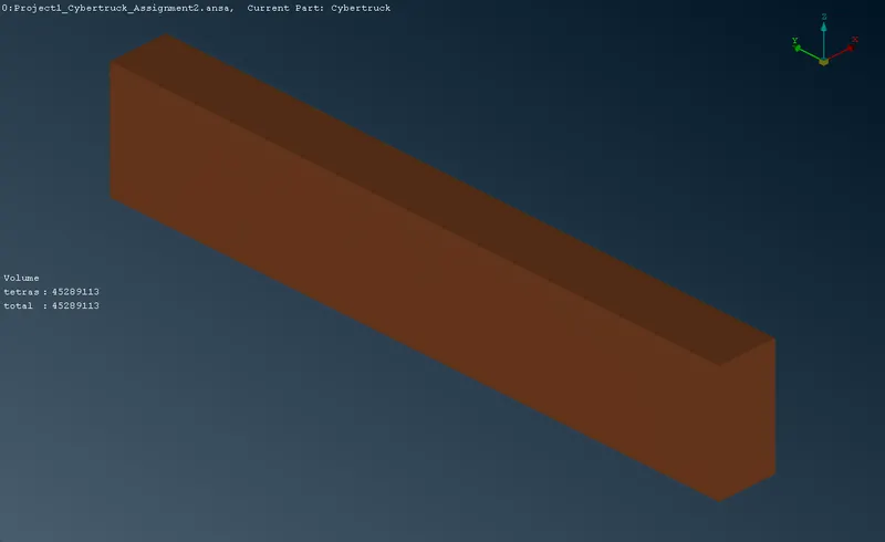
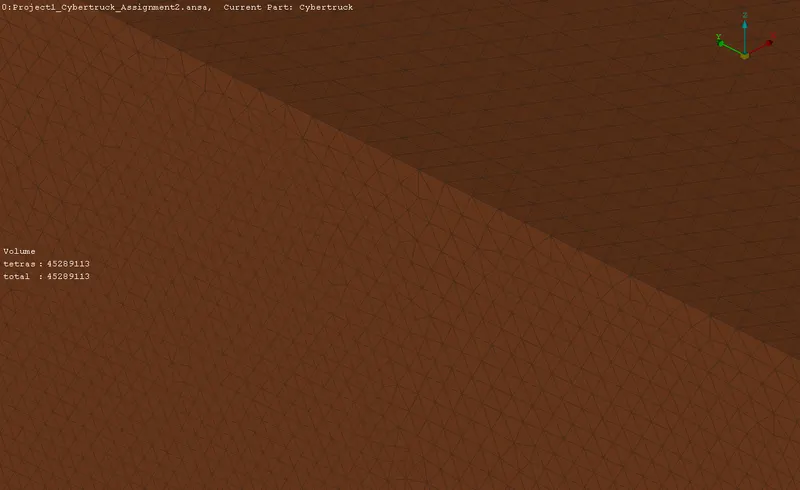
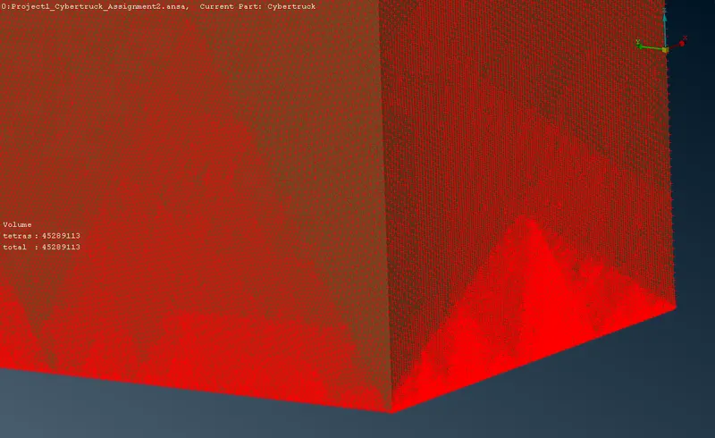
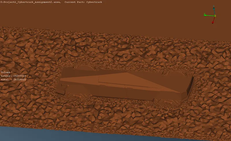
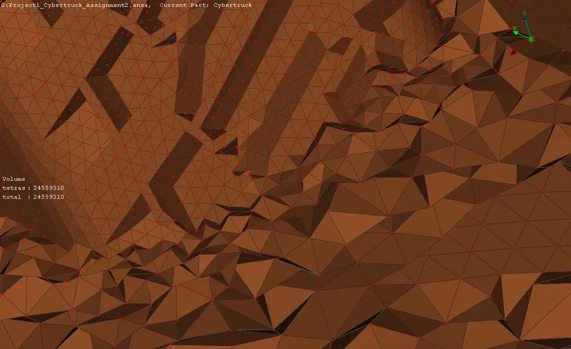
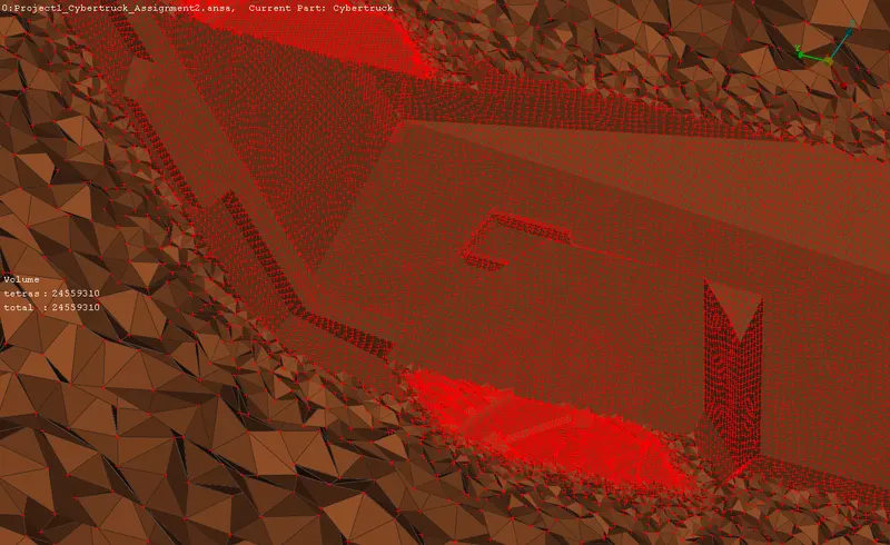
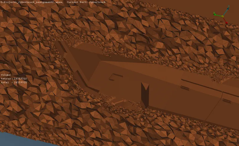
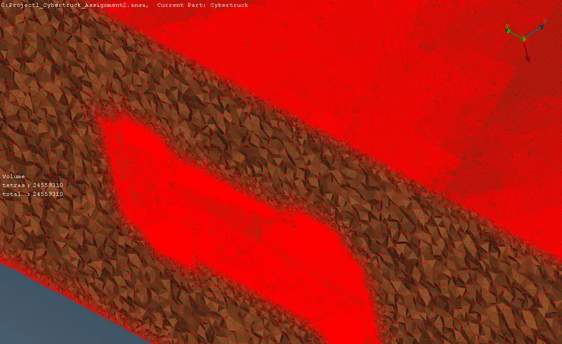
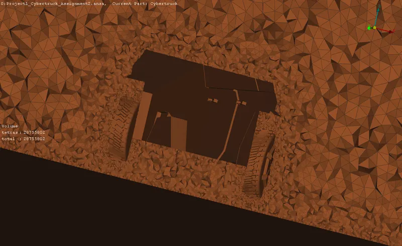
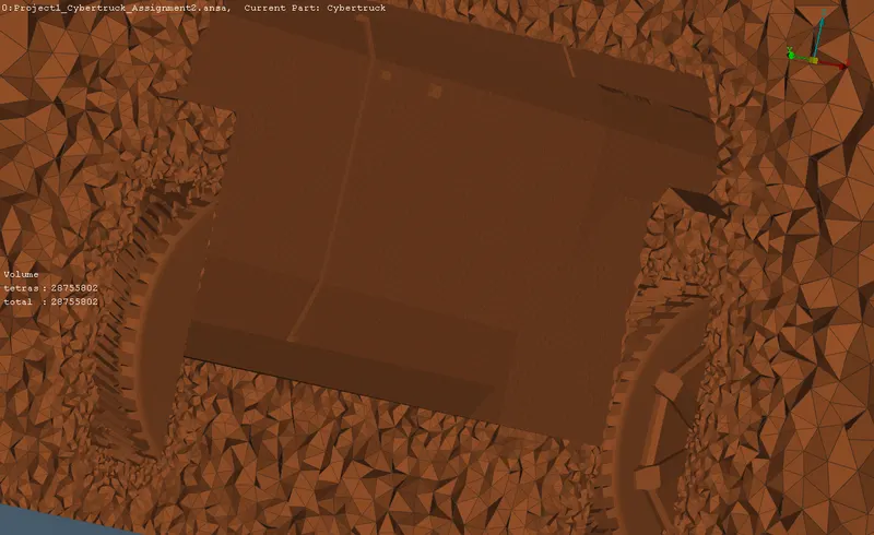
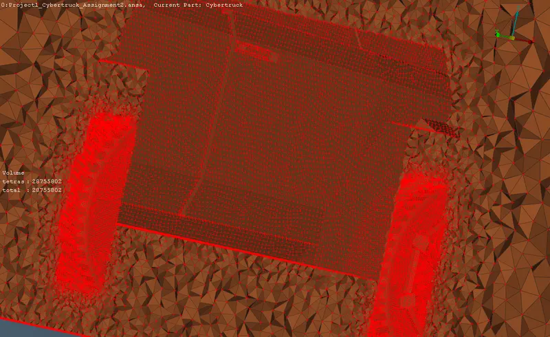
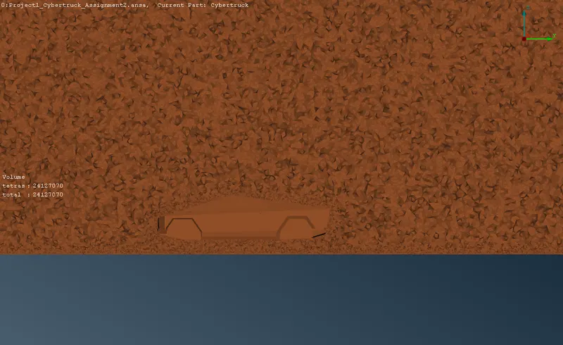
The scope volume is meshed with Tetra CFD elements using the Tetra CFD tool in the volumetric mesh deck.
4 RESULTS:
4.1 Surface mesh
4.1.1 PID 1 Lights
4.1.2 PID 2 Wind shield
4.1.3 PID 3 Body shell
4.1.4 PID 4 Tyres
4.1.5 Wind tunnel
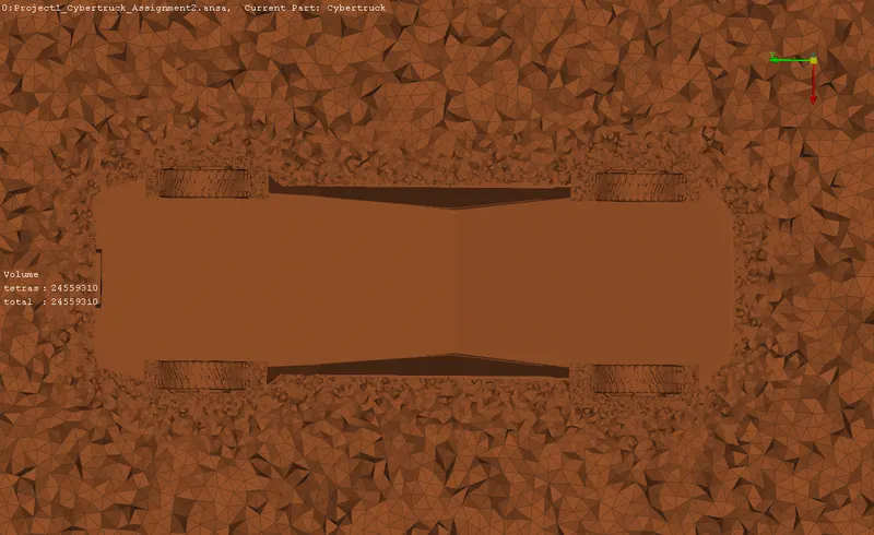
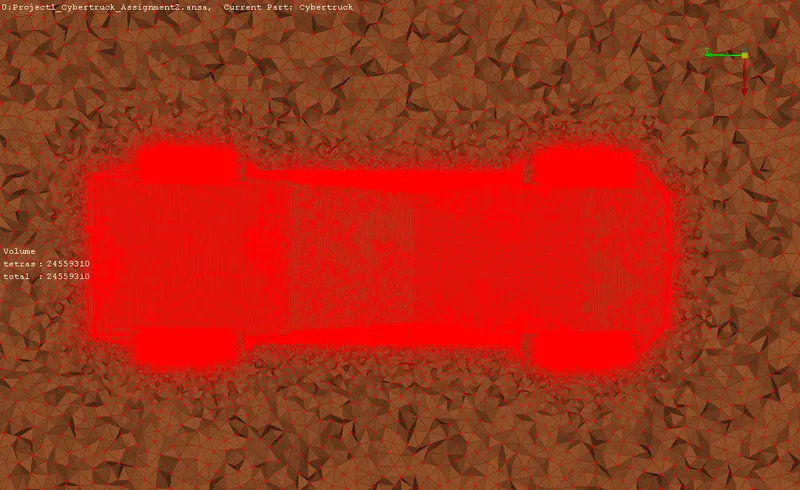
4.2 Volumetric mesh
5 INFERENCE:
The procedure of this meshing includes geometry and pre-surface mesh checks, which gives an assurance of the geometry and the surface mesh respectively. The anomalies detected in the checks are rectified using the built-in fix option for both the checks. Hence the quality of the meshes are confined to a higher assurance. The off-elements are detected with the quality criteria at 20% to 30% allowance with the target element size. All the elements are found to be within the limits of allowance after resolving and optimization of the mesh elements.
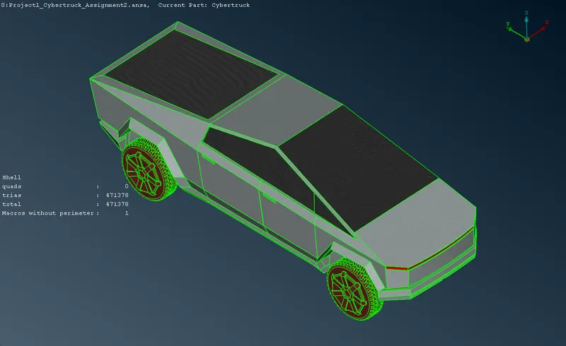
From the results, it can be seen that there are 4,71,378 tria cells in the surface of the truck body of size ranging between 10mm to 30 mm, which generates a convenient volumetric mesh. There is always a compromise between the cell size and the computational leisure. The number of cells directly depend on the cell size defined for the surface mesh. Hence the cell size is maintained bigger enough for the application while having an justification for the computational limits of the system. The minute features of the entities are measured and is used as the target length of the entities. The checks manager verifies the geometry is free from anomalies for volumetric meshing.
The wind tunnel is theoretically cuboid shaped and has 6 surfaces. The roof has a 100mm constant size cells and the floor has 20mm constant cell size. The truck placed closer to the floor surface of the wind tunnel and hence the smaller size of the floor surface cells adds up to the efficiency of computation. The walls have a varying perimeter edges, which gives a varying cell size across the height of the tunnel. This ensures smaller cells near the truck at the bottom, while the cells above are bigger and there is continuous structed variation; which is also a factor for the computational efficiency.
A single volume is defined and meshed which forms the computation space for various solver applications. The pre-surface mesh check manager ensures that the surface mesh is free form anomalies for volumetric meshing. The spacing tool is a useful tool which can provide a varying perimeter length for the cons. The side wall lengths are defined such that the elements in the bottom of the tunnel is small and the elements at the top are big, and there is a structured variation in the element size. The cells around the truck is smaller to increase the efficiency of the solver application, while the cells farther away from the truck are bigger as the scope of application is less at the far outer periphery of the wind tunnel.
6 CONCLUSION:
The Tesla cyber truck prototype model is successfully meshed. The volume is accurate and precise for a CFD application. There are 4,52,89,113 tetragonal cells in the volume are flawless which are generated from the 49,31,360 cells in the surface. The volume has a single Material Id with multiple PIDs for computing purposes. The quality of the mesh is maintained at highest quality assurance criteria to increase the efficiency, while maintaining the computational limits of the system and the solver.
LINK TO THE ANSA FILE:
https://drive.google.com/file/d/15OA3VNs8SqmrtbqCuF38lvi5mHzrzRXO/view?usp=sharing