Week 7 - Minor Project
AIM: To observe the lift and drag characteristics of an airfoil in subsonic and supersonic flow regimes.
1 INTRODUCTION:
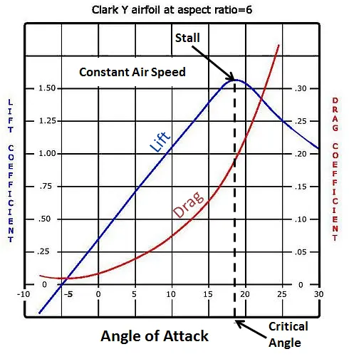
The slope of the linear portion is called the lift slope. For thin airfoils, a theoretical value for the lift slope is 2pi per radian or 0.11 per degree. There is a finite value of Cl at 0 angle of attack and that the airfoil must be pitched down to some negative angle of attack for the lift to be 0. A positively cambered airfoil has negative zero-lift angle of attack. A negatively cambered airfoil has a positive zero-lift angle of attack. A symmetric airfoil has 0 lift at 0 angle of attack.
After a point in the graph, separation of flow occurs over the top surface of the airfoil and the lift decreases. In this condition, the airfoil is said to be stalled. In contrast, over the linear portion of the lift curve, the flow is attached over most of the airfoil surface. The linear portion of the lift curve is essentially insensitive to variations in Reynolds number.
For a cambered airfoil, the minimum value cd does not necessarily occur a 0 angle of attack, but rather at some infinite but small angle of attack. For this angle of attack range, the drag is due to friction drag and pressure drag. In contrast, the rapid increase in Cd which occurs at higher values of alpha, is due to the increasing region of separated flow over the airfoil, which creates a large pressure drag. The friction decreases by increasing the Reynolds number. Moreover, the reynolds number influences the extent and characteristics of the separated flow region, and hence it is no surprise that Cd at the larger values of alpha is also sensitive to the Reynolds number.
Supersonic Airfoil design:
Different types of drag appears on the supersonic airfoil, namely skin friction drag, wave drag and drag resulting from waves due to the lift. Expansion waves are also created along the airfoil at the top surface near the front or leading edge and at the bottom surface along the trailing edge. To counter these drag-inducing effects, the airfoil cross-section is generally made to be thin, with sharp leading and trailing edges. These types of airfoils are also called swept airfoils. The this leading edge creates an oblique shock wave, which creates less drag then the bow shock wave. A reduction in parallel airflow reduces wave drag also. Therefore by designing thin airfoils with greater sweep angles, it is possible to fly at a higher Mach number before a wave drag is created.
At high speed, airfoils are exposed to shock waves, which alter the pressure distribution to increase drag. Supersonic airfoils are usually swept with a thin cross-section to reduce drag.
2 COMPUTATION:
2.1 Domain creation
2.1.1 Domain and airfoil geometry drafting
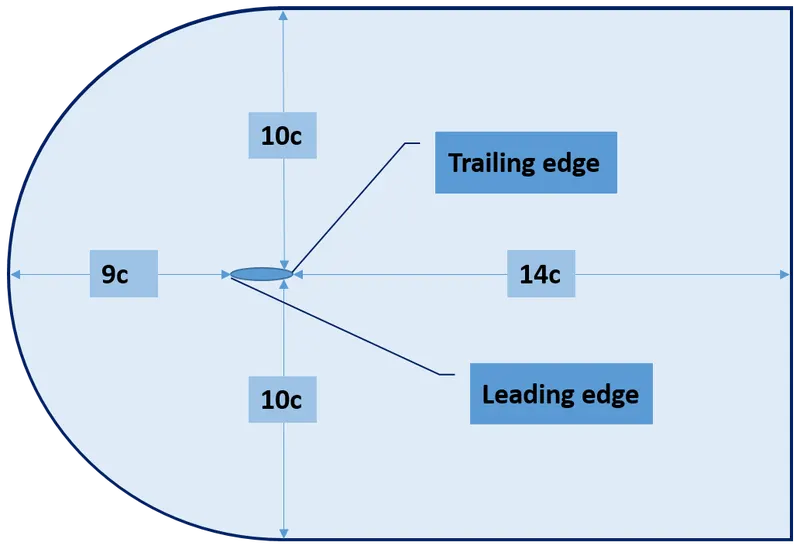
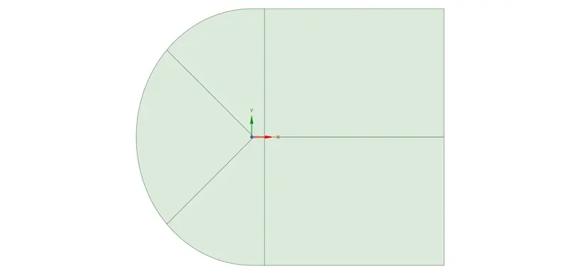
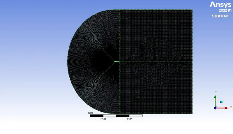
The airfoil is surrounded by 6 faces forming the domain. The far-field and near field are designed by the wind tunnel parameters for an airfoil.
Wind tunnel parameters for airfoil:
Far field and near filed faces:
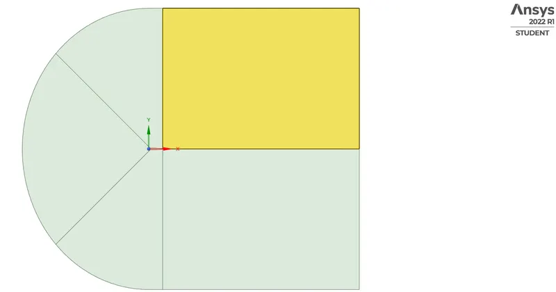
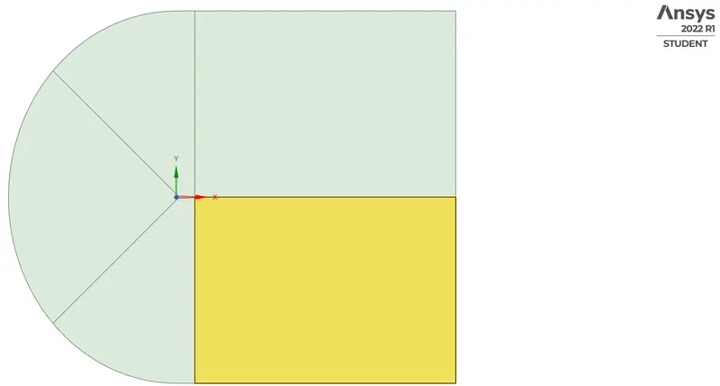
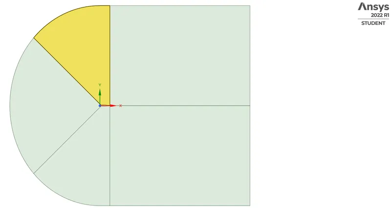
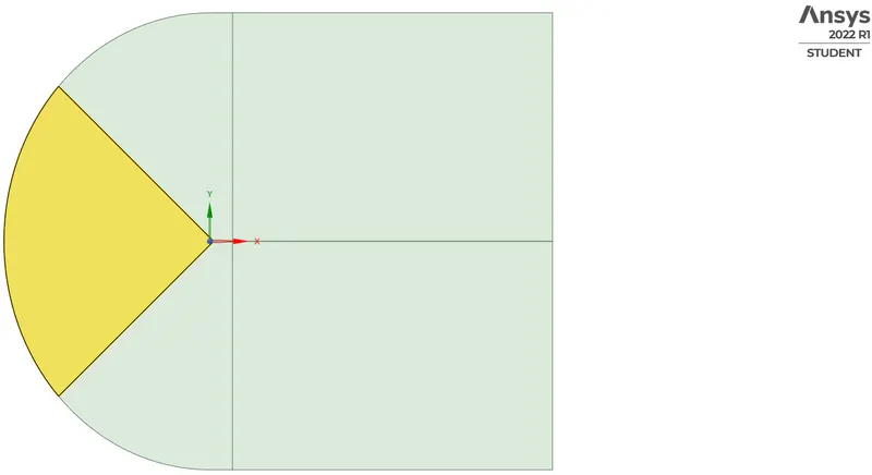
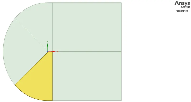
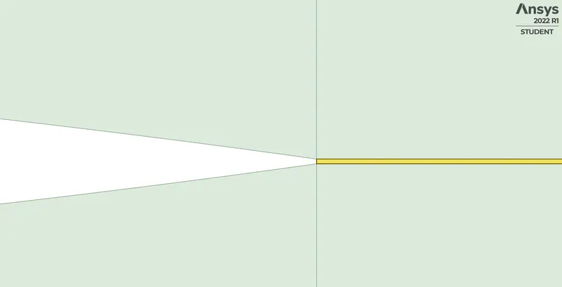
The domain and airfoil geometry: The entire geometry is made 2 dimensional, owing to the efficacy of computing.
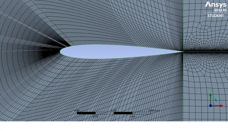
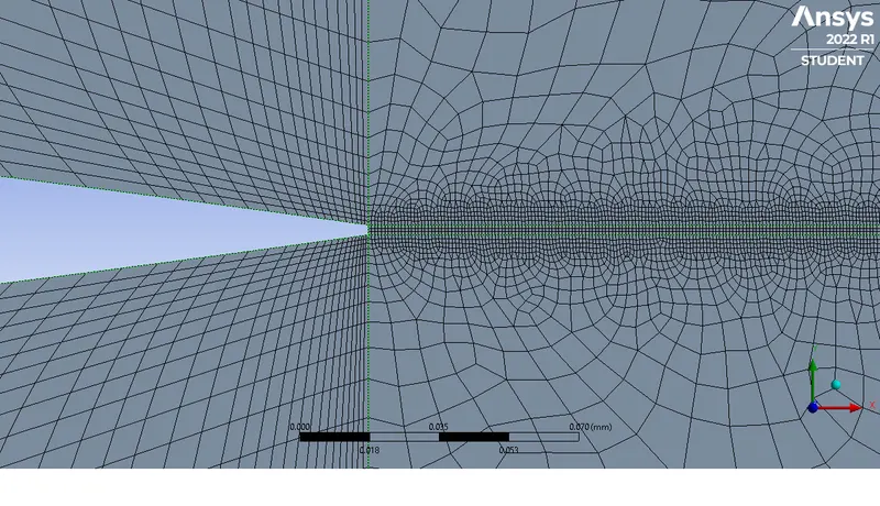
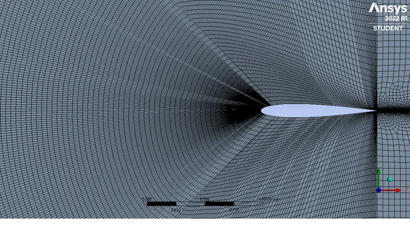
2.1.2 Meshing the geometry
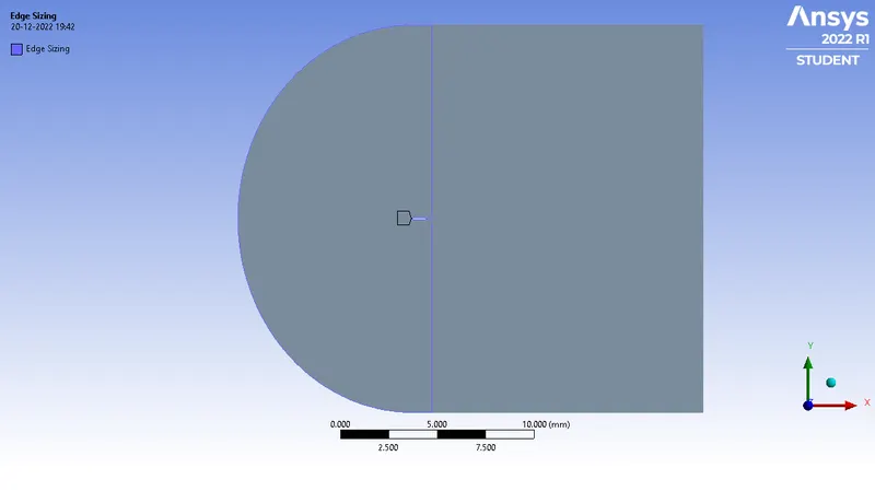
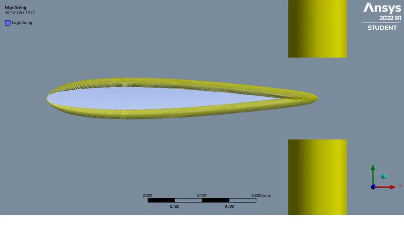
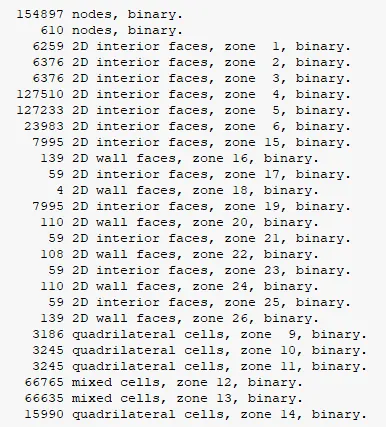
Edge sizing is given in the edges with a value of 100 divisions.
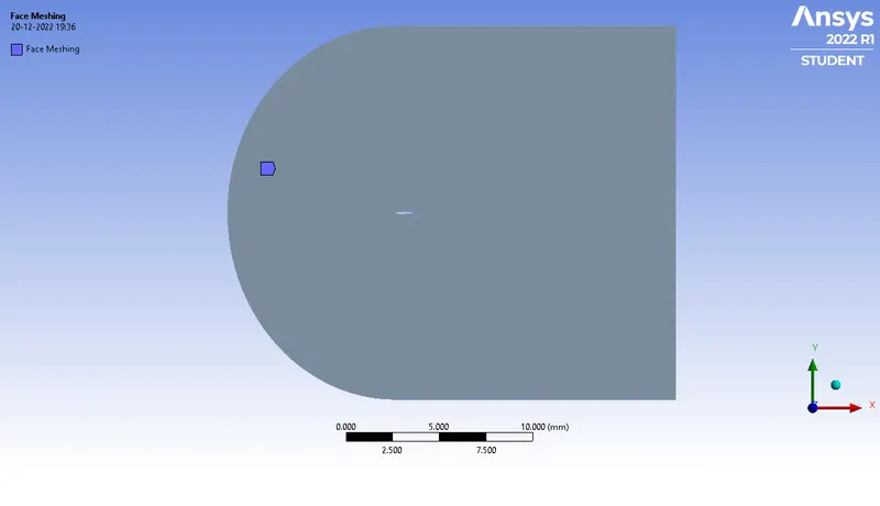
Face meshing is given at the forward face to maintain structured mesh.
2.1.3 Setting up domain parameters
The inlet velocity is determined by using the Mach number and Reynolds number relation. For a 1m chord length airfoil, with the standard air density and viscosity, the Reynolds number for a supersonic and subsonic flow is calculated.
| Inlet velocity (m/s) | Density (kg/m3) | Length (m) | Kinematic viscosity (kg-m/s) | Reynolds no. | Mach no. | |
| Subsonic flow | 212 | 1.225 | 1 | 0.0000186 | 1,40,00,000 | 0.6 |
| Supersonic flow | 380 | 1.225 | 1 | 0.0000186 | 2,50,00,000 | 1.1 |
2.2 Run cases:
2.2.1 Subsonic flow
| Case 1.1 | Case 1.2 | Case 1.3 |
|
AoA = 5deg Velocity = 212m/s |
AoA = 10deg Velocity = 212m/s |
AoA=15 deg Velocity = 212m/s |
2.2.2 Supersonic flow
| Case 2.1 | Case 2.2 | Case 2.3 |
|
AoA = 5deg Velocity = 212m/s |
AoA = 10deg Velocity = 212m/s |
AoA = 15deg Velocity = 212m/s |
2.3 Solver setup
2.3.1 General solver settings
For both flows, a density-based solver is selected owing to the velocity beyond 50m/s
2.3.2 Turbulence model selection
For both flows, Inviscid model is selected as it is efficient in solving high speed flows.
2.3.3 Material selection
Ideal gas is selected as both flows remains in the compressible turbulent regime.
2.3.4 Boundary conditions
For subsonic flow, The inlet velocity is 212m/s, which is split into X and Y components based on the angle of attack
For supersonic flow, the inlet velocity is 380m/s, which is also split into X and Y components based on the angle of attack
The inlet is made a pressure-far field with Mach number and X,Y components. The pressure at standard atmosphere and mean sea level is used as 101325 pa and 323K
The outlet is made a pressure outlet with 0pa.
2.3.5 Solution and post-processing:
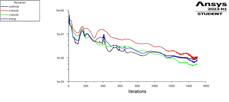
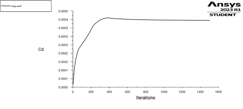
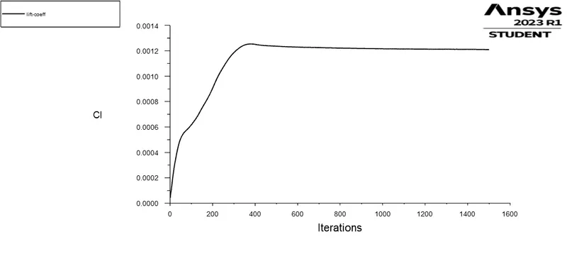
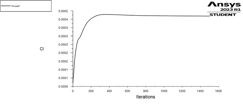
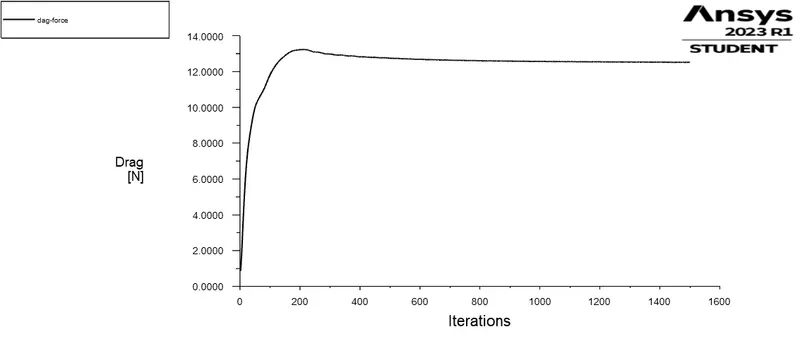
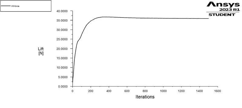
A pressure and velocity contour is defined. Along with co-efficient of lift, co-efficient of drag, the lift and drag forces are plotted with direction vectors defined based on the angle of attack.
The direction vectors are defined in the drag and lift characteristics based on the angle of attack.
3 RESULTS:
3.1 Computed plots:
3.1.1 For Subsonic flow:
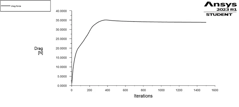
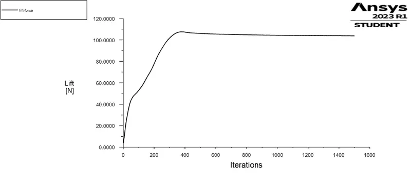
3.1.2 For Supersonic flow:
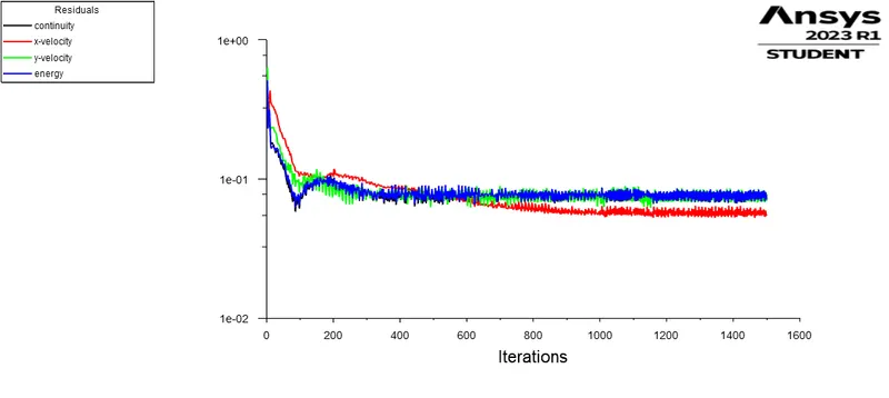
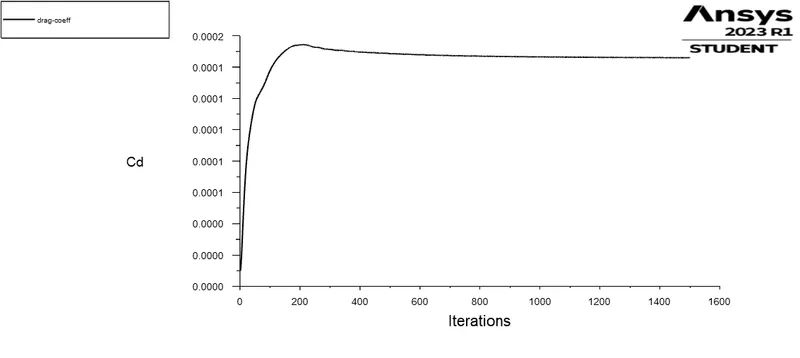
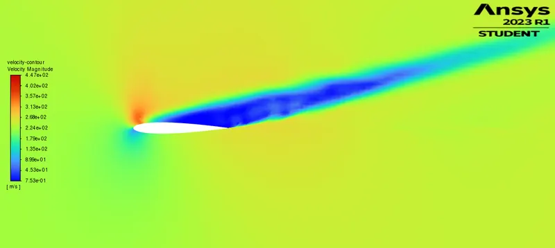
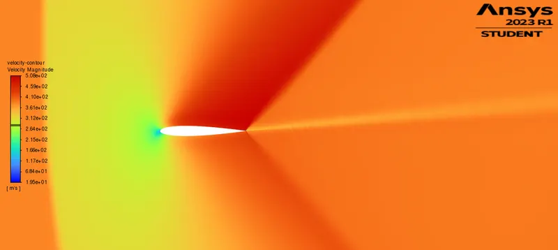
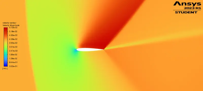
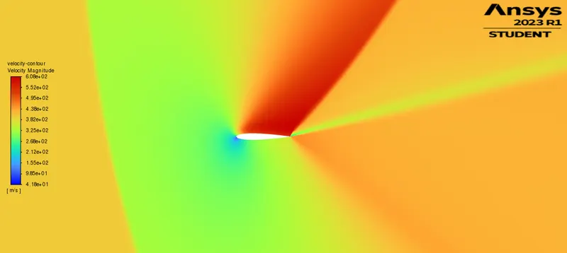
3.2 Computed contours:
| Pressure contour | Velocity contour | |
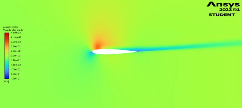
| Case 1.1 | 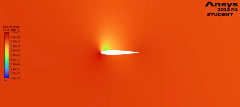 |
 |
| Case 1.2 | 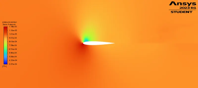 |
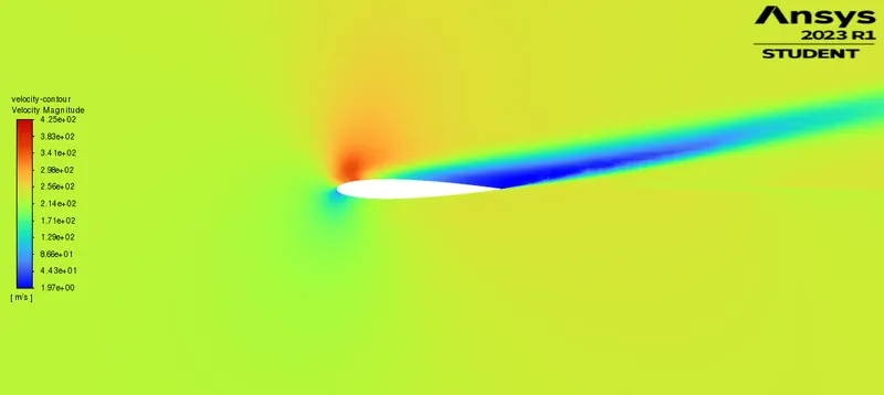 |
| Case 1.3 | 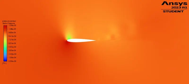 |
 |
| Case 2.1 | 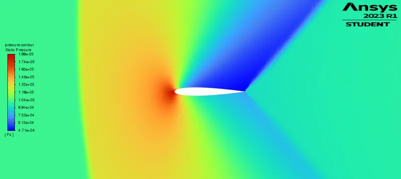 |
 |
| Case 2.2 | 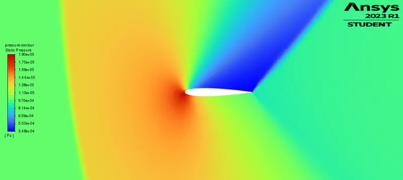 |
 |
| Case 2.3 | 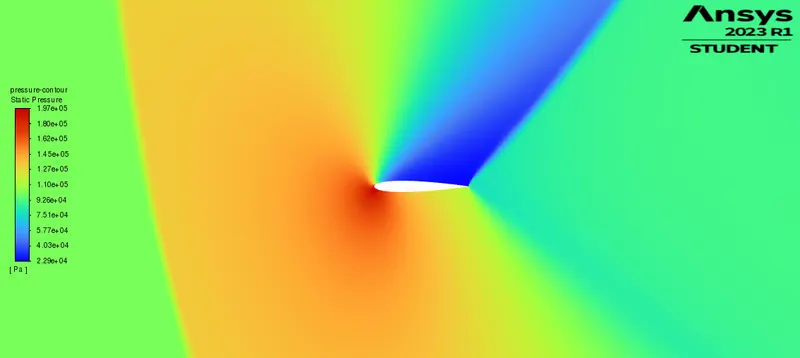 |
 |
3.3 Computed values:
| Cl | Cd | Fl | Fd | ||
| Subsonic | Case 1.1 | 0.00017 | 0.000014 | 14.89 | 1.21 |
| Subsonic | Case 1.2 | 0.00018 | 0.000032 | 15.71 | 2.76 |
| Subsonic | Case 1.3 | 0.00019 | 0.000049 | 16.43 | 4.23 |
| Supersonic | Case 2.1 | 0.00041 | 0.00014 | 35.2 | 12.51 |
| Supersonic | Case 2.2 | 0.00083 | 0.00024 | 71.89 | 21.07 |
| Supersonic | Case 2.3 | 0.0012 | 0.00039 | 103.71 | 33.77 |
4 INFERENCE:
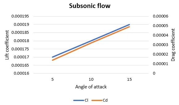 |
From the results, the Cl and Cd versus the angle of attack is studied. It is observed that both the values are found increasing steadily. The maximum pressure seen as 197kPa for the 15 deg angle of attack. The max pressure region is seen just below the nose of the airfoil, because of the first point of attack of the fluid particles. The airfoil also seems to leave a trail behind it in case of higher angles which is nothing but the drag, where the fluid particles show a fall in velocity and pressure. In higher speeds, these particles in the wake region forms the vortices which drags the airfoil. These can be overtaken by reducing the vorticity or turbulence of the particles on the critical mach number point. This critical mach number can be approximated and efficiently placed by studies and analysis, which increases the performance. |
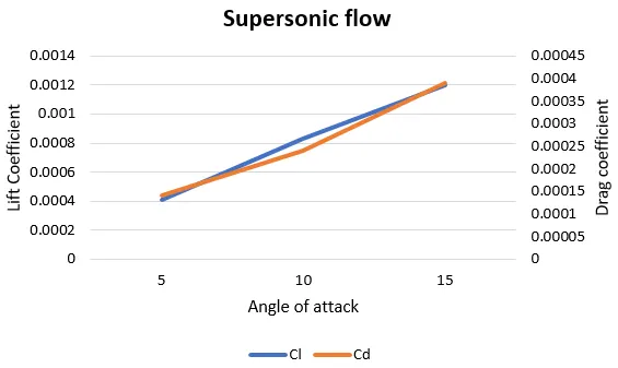 |
For supersonic speeds, it can be seen that the Cl and Cd values have increased with the lift and drag forces. The Cl and Cd values seem to be steadily increasing in accordance to the angle of attack values. From the velocity and pressure contour, the shock waves can also be computed. The pressure and velocity values seem to drastically change beyond the shock wave region. Using an Inviscid solver for the Mach 1.1 gives more accurate results of aerodynamic behaviors of the airfoil. The lift values are higher than the drag values, which proves that there is some lift even in a symmetric airfoil. A the angle of attack increases, the pressure on the nose tip increases, as it is the first point of attack. The wake region above the airfoil has less pressure and velocity than the other region, which is due to the turbulence in fluid flow. This can be optimised by using optimum critical mach number point in chord length. |
5 CONCLUSION:
Thus the airfoil with a symmetric geometry with respect to the chord length is simulated for subsonic and supersonic conditions, and the results are found to be in accordance with the literature survey. The lift and drag values corresponding to the angle of attack is studied. For supersonic behaviour formation of the shock waves around the airfoil can also be observed in the study.