Week 2 Challenge : Surface meshing on a Pressure valve
SURFACE MESHING ON A PRESSURE VALVE:
Aim: To remove the geometrical errors on the given pressure valve model, to do topology cleanup and do a surface meshing on the model with 3 different mesh lengths
Introduction:
Topology is how the surfaces connect to adjacent surfaces of a part. Surface connectivity is controlled by the associated surface edges called 'Cons'. If a surface edge is associated with only one surface it is known as ' Single cons'; followed by double cons and triple cons respectively. Topology repair consists of correcting connectivity errors between adjacent surfaces. The possible errors include unconnected adjacent surfaces, duplicate surfaces, missing surfaces, overlapping surfaces etc. The goal of topology repair is to restore the surface data to a perfectly clean representation of the part. The general process is to figure out what the ideal surface connectivity of the part should be.
Some of the common errors could be due to bad geometry representation, small details in the model, compatible topology for meshing scheme and conformal topology for assemblies. As a result of translation errors between CAD representations, errors or differences in the way the geometry is interpreted may occur. Depending on the severity of the problem, sometimes a mesh can be generated even with a less-than-perfect geometric representation. In some cases there exist small details in the geometry that, if meshed, would result in very small elements and a potentially huge element budget. Small curves and surfaces can sometimes result from details in the design solid model that may not be necessary for analysis or mat even be a result of careless construction of the CAD model. Several meshing algorithms, such as the structured, mapping and sweeping techniques require a specific configuration of vertices, curves and surfaces in order to operate. Operations to decompose the geometry into a meshable topology are often needed. other unstructured techniques like paving and tetrahedral meshing do not require decomposition. Also, Assemblies of parts are often required to have conformal mesh across their interface. The operations imprint and merge are often required to connect parts together so that when meshed, the representation will be a single continuous mesh. However, in most if not all of the cases, it is necessary to resolve all the features, errors, unstructured techniques before meshing is done.
ANSA has a variety of tools varied among several groups for facilitating geometry cleanup. Surface and faces can be separately worked for cleanup with the tools available. ANSA also has a geometry checkup manager which can detect the errors in the different entities of the part model. This check manager can directly visualize the errors in the part model, which can later be worked upon for cleanup.
Procedure:
Step 1: Initial geometry check:
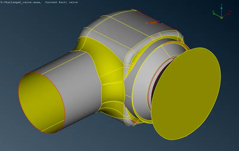
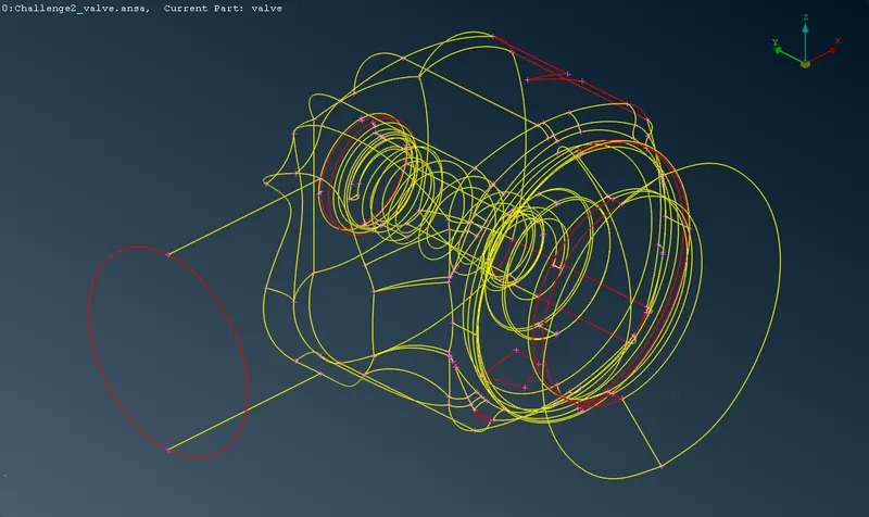
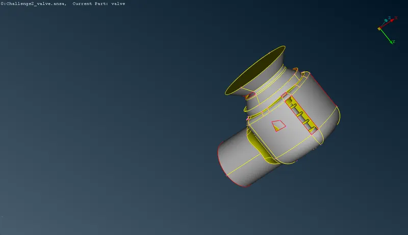
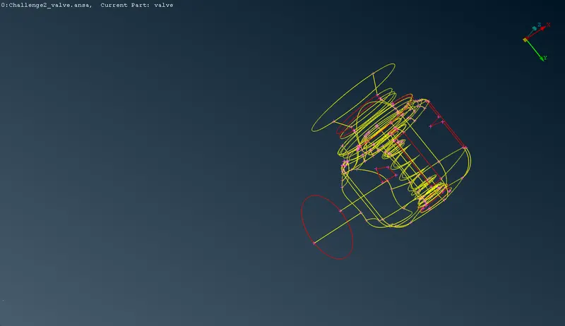
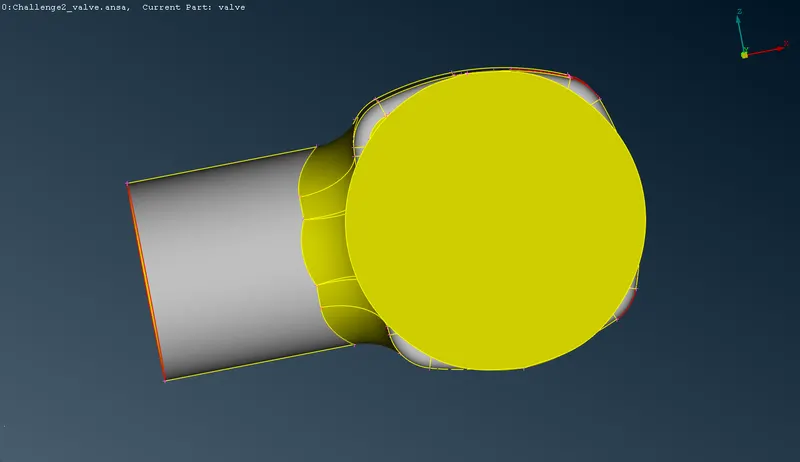
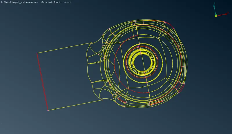
The checks manager is opened and the geometry check is run for various features like cons, overlaps, cracks, interactions, and unchecked faces. The errors executed can be directly visualized in the drawing window by translating from the check window. All the single cons and the errors are initially detected.
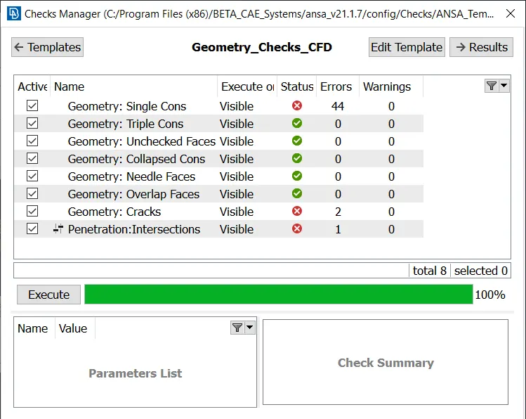
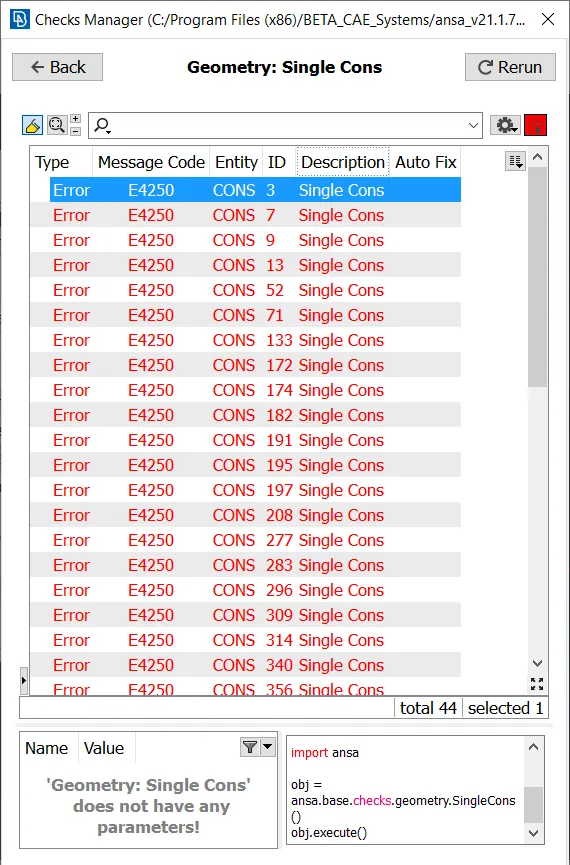
The default geometry check translated for visual display in the drawing window. The red lines are the single cons, yellow lines the double cons and the green lines denote the triple cons. Red coloured single cons are to be eliminated, while the green colored triple cons need not necessarily be a kind of an error.
Step 2: Topology cleanup process:
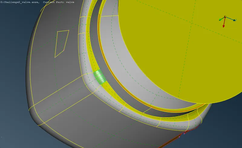
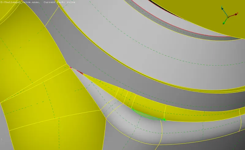
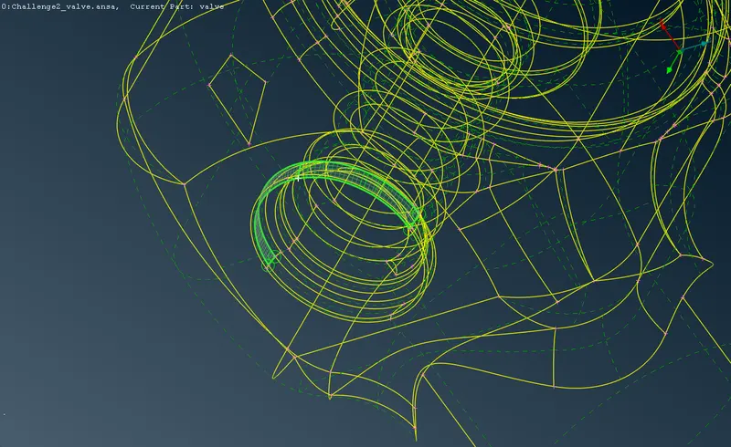
Various single cons and errors shown in the geometry check is addressed and various tools from the faces and surfaces group in the topo menu is used to cleanup the geometry.
| Tools used: 'New' face - 'Existing surface' option | 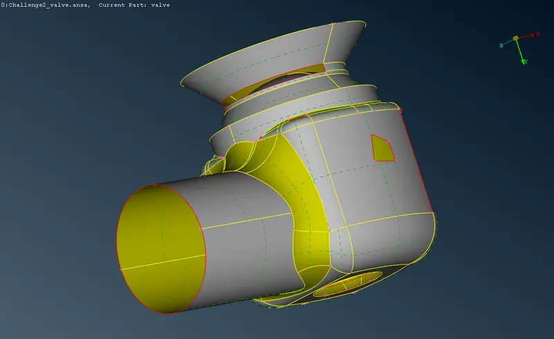 |
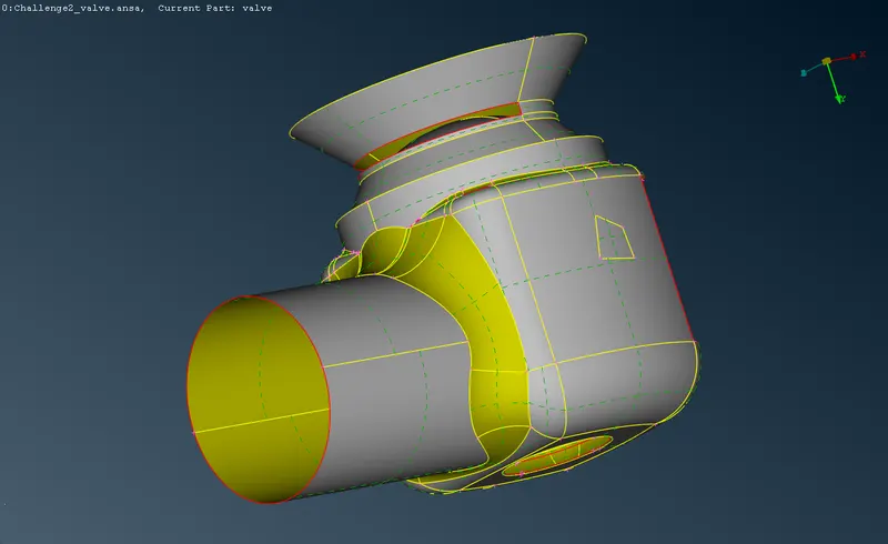 |
| Tools used: 'Fill hole' | 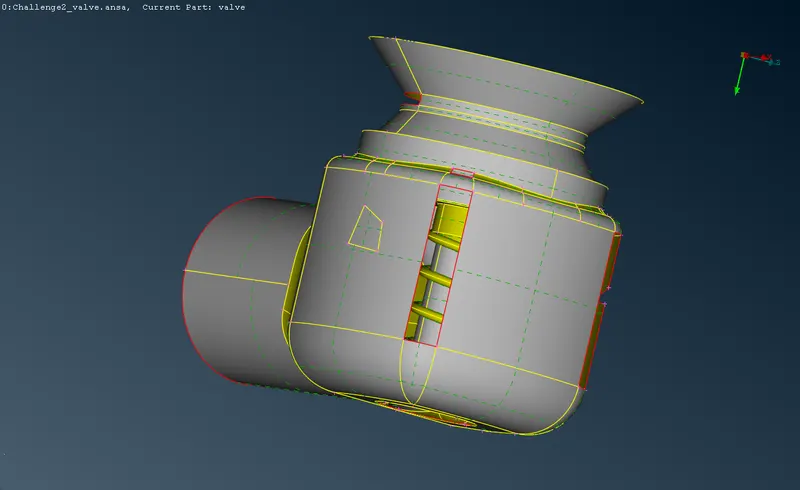 |
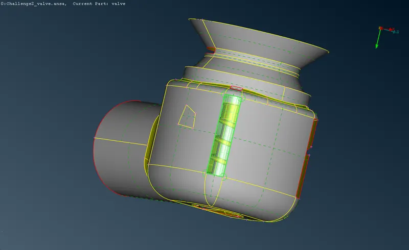 |
| Tools used: 'Fill hole' | 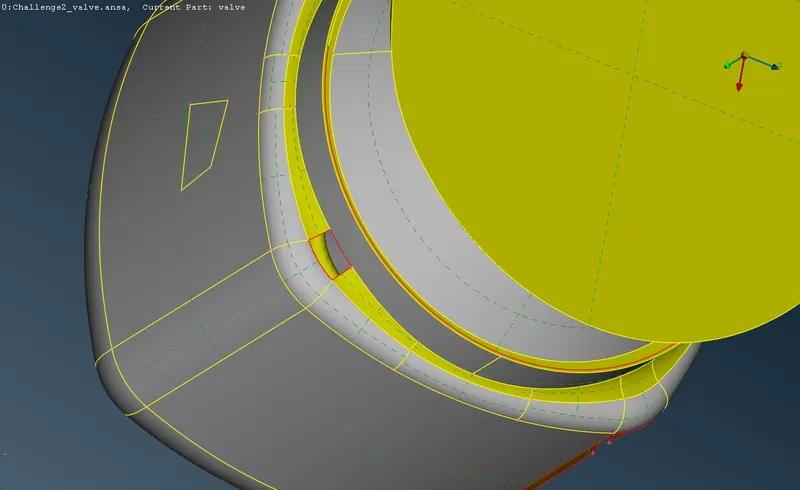 |
 |
| Tools used: 'Fill hole' | 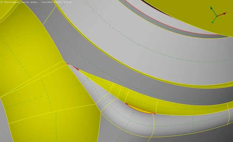 |
 |
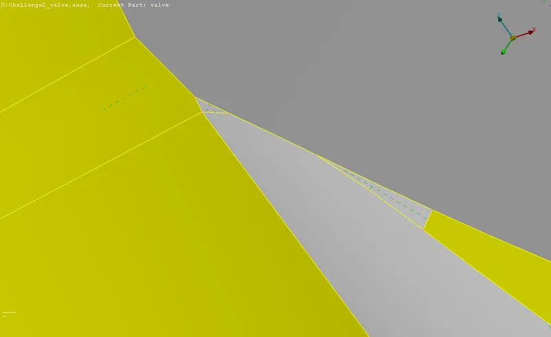
| Tools used: 'Fill hole' | 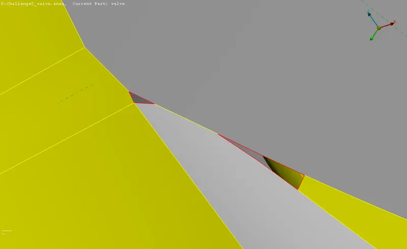 |
 |
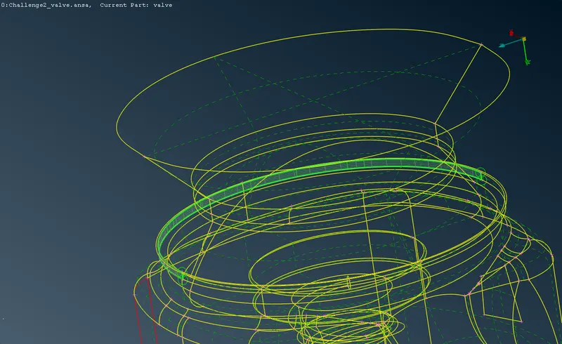
| Tools used: 'New' face - 'Coons' option | 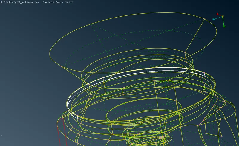 |
 |
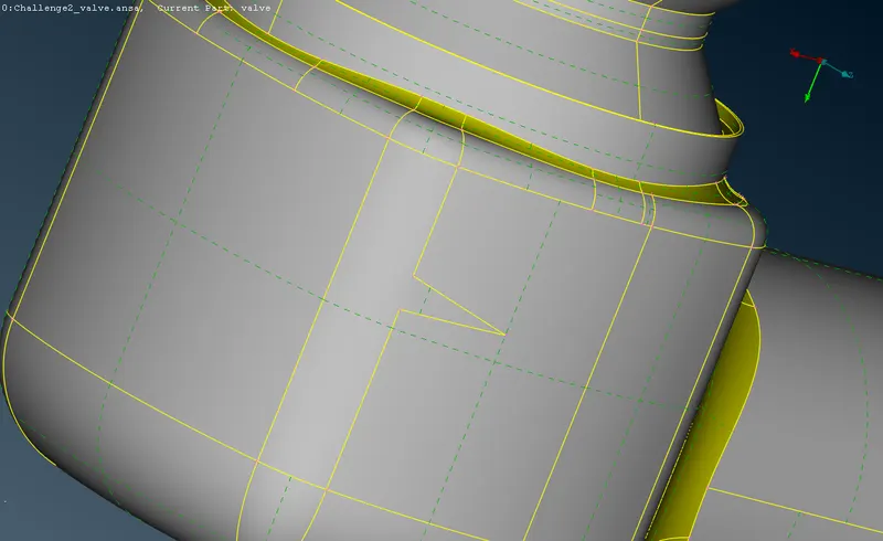
| Tools used: 'Fill hole' | 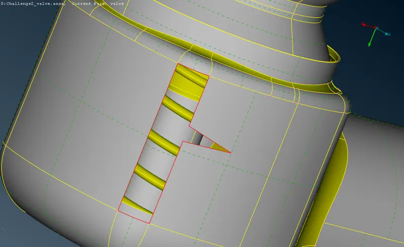 |
 |
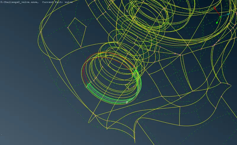
| Tools used: 'New' surface - 'coons' surface option with ENT mode | 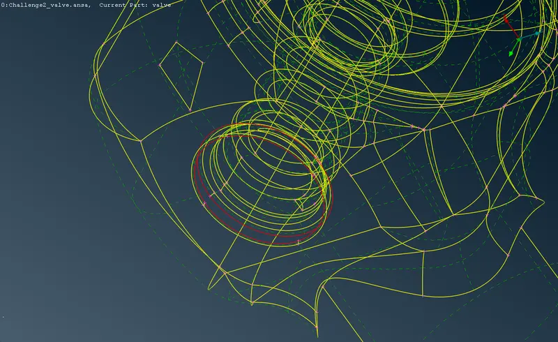 |
 |
| Tools used: 'New' surface - 'coons' surface option with ENT mode | |
 |
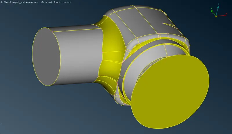
| For volumetric meshing, the geometry should be a closed one, hence, inlet and outlet are closed with 'Fill hole'. | 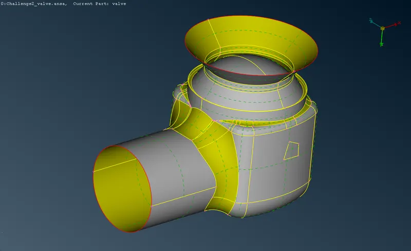 |
 |
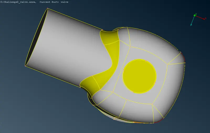
| The holes are closed with 'Fill hole' option. | 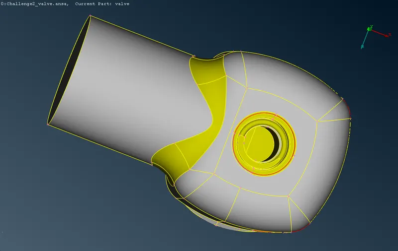 |
 |
Step 3: Final geometry check:
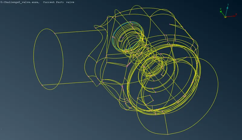
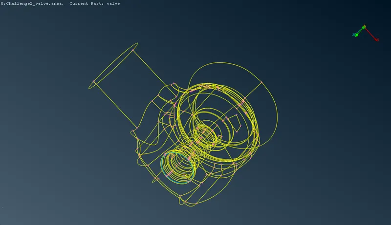
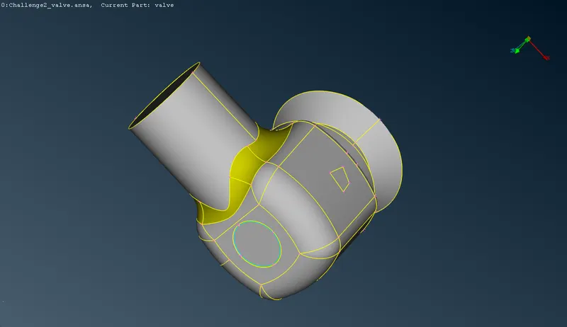
Final geometry check is done with the same features from the initial geometry check. Since the geometry check has given only the triple cons as errors, there are no other errors; and the triple cons in all the faces of this part model forms a structured geometry, hence the geometry is perfect for meshing.
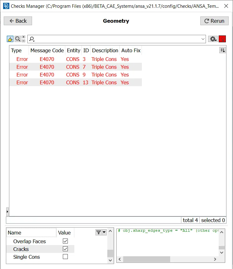
The triple cons detected from the geometry check is neglected as the surface topology is more than a sufficient for this model to perform a meshing operation.
Step 4: Assigning PIDs:
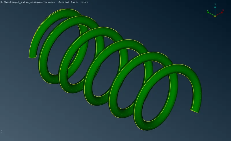
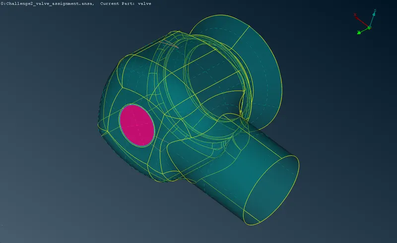
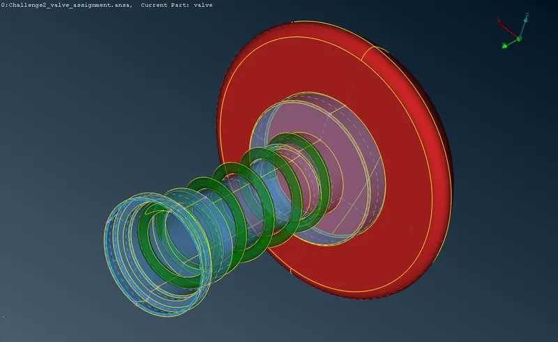
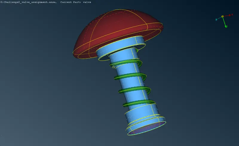
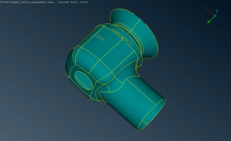
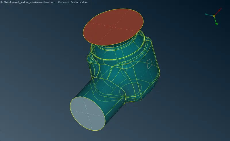
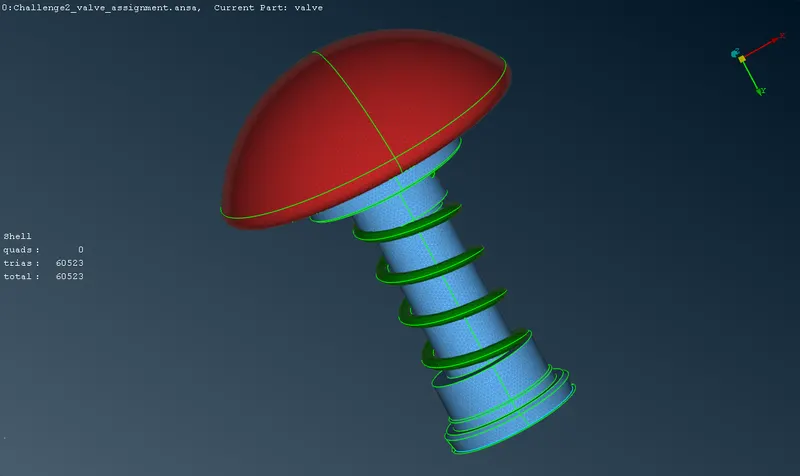
PID are assigned among the spring, base, valve head, column, body, inlet and outlet. Colour coding ig givenfor the PIDs to visually recognize the various PIDs. This PID assigning is helpful for meshing as varying mesh length can be given to different PIDs based on the requirement and minimum size of the cells.
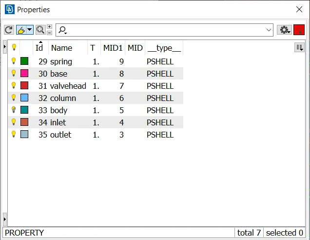
Colour coding is given to visually recognize the various PIDs.
Step 5: Meshing:
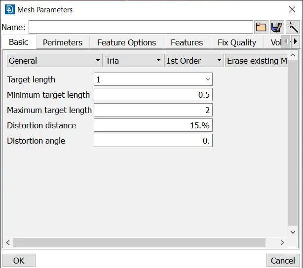
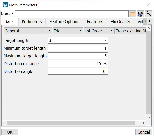
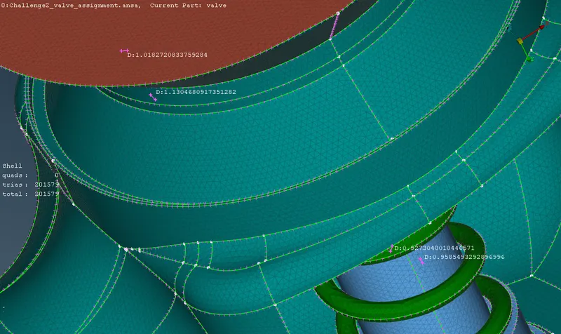
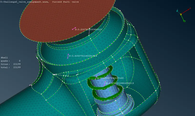
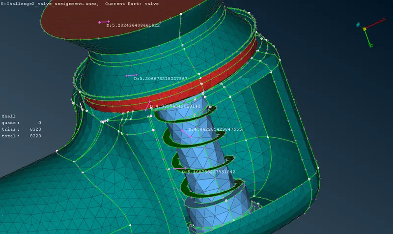
Tools like 'Spot Mesh' and 'Mesh - 'Visible' option is used to generate the mesh. Spot mesh is used to mesh various surfaces and PIDs individually. maximum and minimum lengths are defined with the 'Tria' option for generating triangular shaped cells within the mesh limits defined. 'Measure' tool is used to verify the lengths of the cells generated in the mesh. different locations and orientations of the cells are measured to verify the efficiency of the ANSA mesh generation.
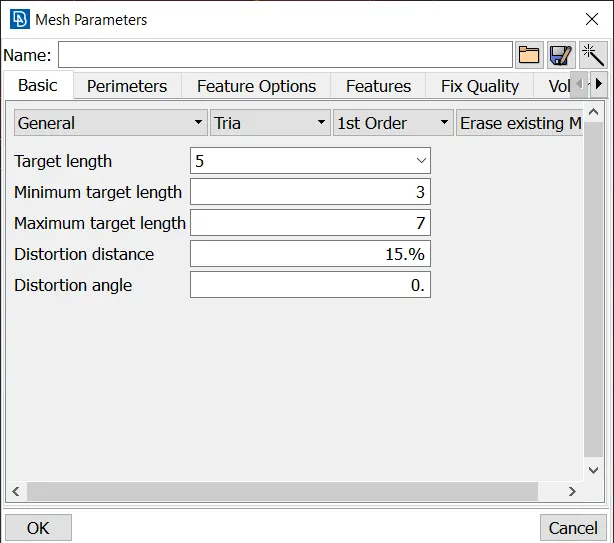
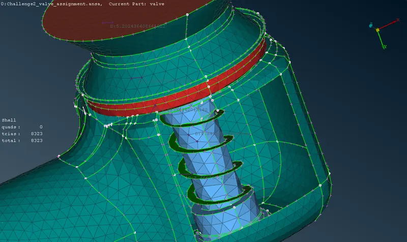
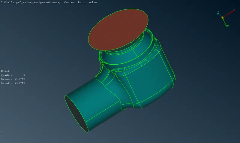
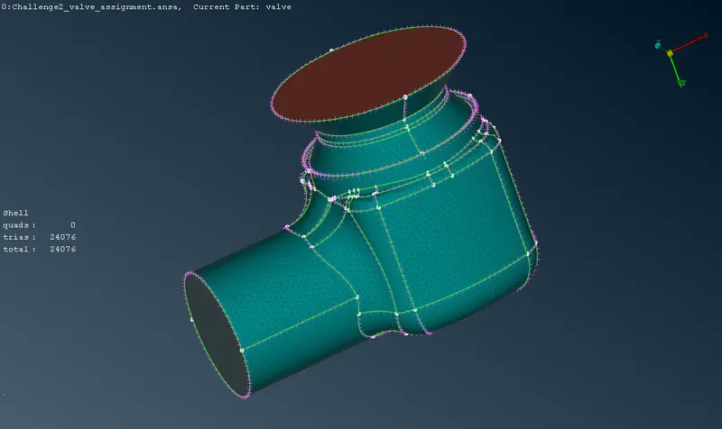
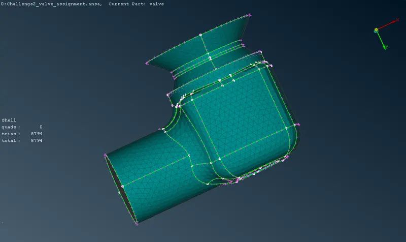
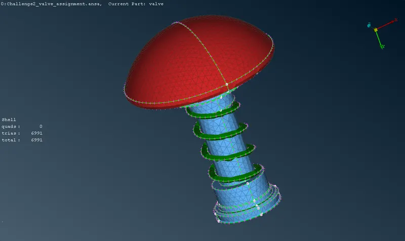
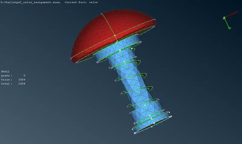
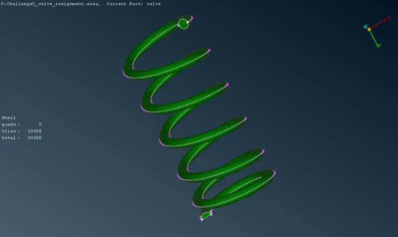
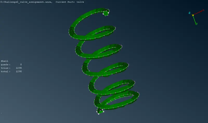
Meshing is done across 3 different lengths with the same method to study the efficiency of the ANSA meshing.
Mesh length variables:
|
Case 1: Element type: Tria Element size: 1mm |
Case 2: Element type: Tria Element size: 3mm |
Case 3: Element type: Tria Element size: 5mm |
Results:
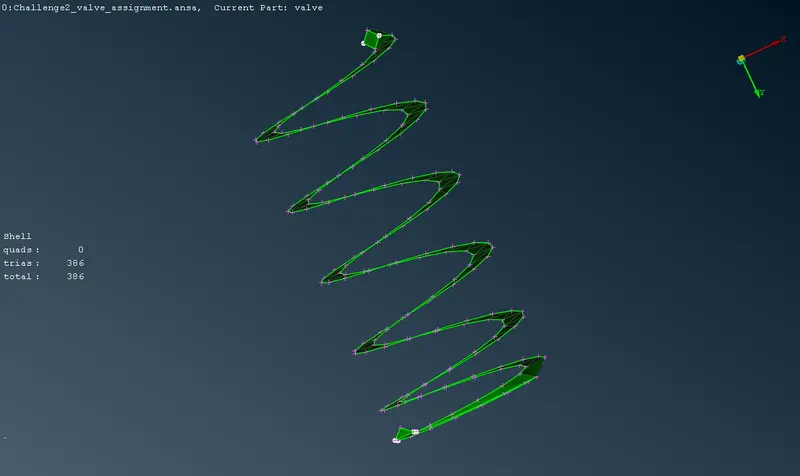
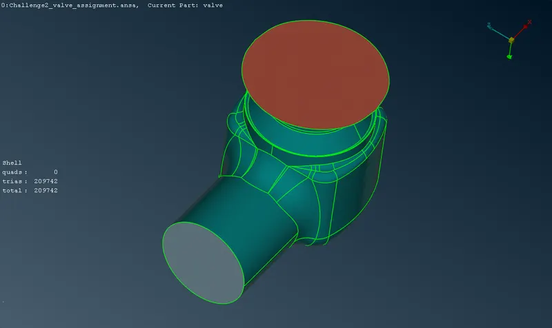
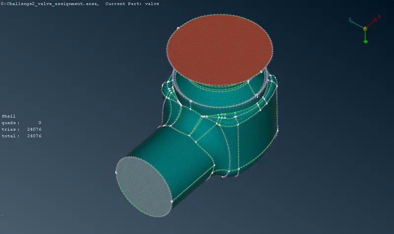
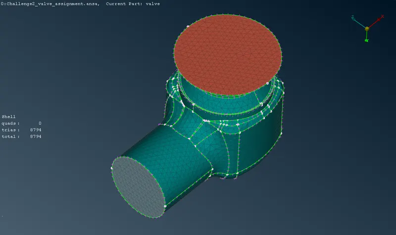
| Case 1: 1mm Tria | Case 2: 3mm Tria | Case 3: 5mm Tria |
 |
 |
|
 |
 |
 |
 |
 |
 |
 |
 |
 |
 |
 |
 |
 |
 |
 |
Inference:
From the results, it is evident that the mesh with the lowest length has the smoothest surface, which is the most comfortable for further analysis. In the case of the Spring PID, the mesh with 5mm length is seemed to have a skewed geometry; because the min and max of the mesh length is does not have the mean diameter of the spring in its range. Further measuring, it si found out that the mean diameter of the spring is about 3mm, in which generating a 5mm mesh is not feasible. Hence a smooth mesh without damaging the geometry s seen in the 1mm and 3mm lengths. All the other entities seem to be having a a damage proof mesh with all the lengths, yet has a smooth surface topology in the mesh with 1mm length. the valve head for an instance has an uneven topology in the 5mm mesh variant as it has curved surfaces and rounded edges. hence the 1mm mesh variant is preferred to preserve the geometry. The measure tool is used and the mesh lengths are verified and are found to be in accordance with the defined mesh length.
During topology cleanup process, various surfaces at different orientation requires different tools for resolving. In this model, a combination of several tools and options are used. Then the PIDs are defined to individually identify the entities and group them according to the definition of ANSA solver. Dummy PID is deleted after removing the dummy faces which is observed to have been overlapping on another face. 'Undelete' option is used to identify those overlapping faces which has been deleted previously and 'Topo' tool is used to resolve the anomality. Then the dummy PId is deleted after which all the PIDs have unique entities.
Conclusion:
The geometry of the valve model is thus cleaned for the topology features, and verified with the built-in geometry check feature. Meshing is done with 3 different mesh lengths and the results are studied for the dependency of the mesh length on the maximum and minimum lengths of the part model. The techniques used while drafting the geometry also has an influence on the max and min mesh length parameter, which is also studied in the analysis.
Link to the ANSA file:
https://drive.google.com/file/d/1ZaEv3hrLks_13y2_79eaBjlRh6_RGwth/view?usp=sharing