Week 3 - External flow simulation over an Ahmed body.
Aim:
To understand the flow characteristics of the ahmed body in significance to the negative pressure in the wake region and the point of separation.
Introduction:
Ahmed Body:
An ahmed body is a generic car body, also a simplified car model. The airflow around the ahmed body characterises the essential flow features around an automobile body. It is used for numerical validation and describing turbulent flow features. It has a rear slant portion with variable slant angle.
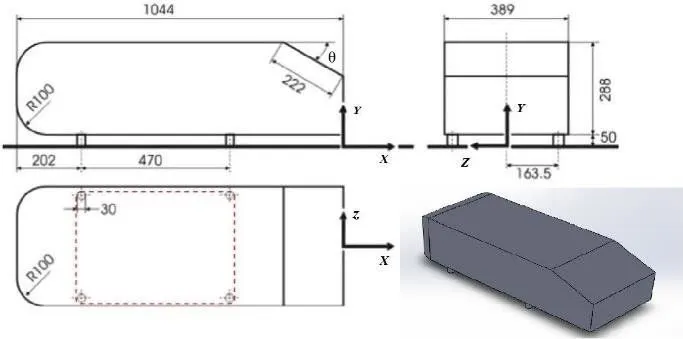
It was first used with experimental data to validate turbulent flow models. The experimental setup includes LSTM (Low Speed Wind Tunnel) and a 2-component Laser Doppler mounted on a traversing system. The flow region which contributes more to the automobile's drag and hindrances to numerical predictions is the wake flow after the slant portion of the model. The location at which the flow separates describes the flow separation and also the drag force. The significance of this model lies in validation of the exact simulated predictions.
Y+ value and inflation layer thickness calculation:
The Y+ is a non-dimensional term that defines the coarseness or fineness of the grid. It is used to define whether wall functions need to be used or not. From the desire Y+ value, the first layer thickness is found by way of finding the total thickness of the inflation layers.
`Re=(rhovl)/mu`= (1.225*25*1)/0.000017894 = 1711467
`Cf=(0.026)/(Re^(1/7))`= 0.026/(1711467^(1/7)) = 0.0033
`tauw=(Cf rho v^2)/2` = (0.0033*1.225*25*25)/2 = 1.2632
`mut= ((tau w)/ rho)^(1/2)` = (1.2632/1.225)^(1/2) = 1.0155
For K-Epsilon model Y+ = 50.
`Y = (Y^+ * mu)/ (mut *rho)` = (50*0.000017894)/(1.0155*1.225) = 0.000715 or 0.7mm
Total thickness = Y * (1.2^(number of layers -1)) = 0.000715 * (1.2^16)= 0.0005309 or 5.3mm
For K-Omega model Y+ = 2.
`Y = (Y^+ * mu)/ (mut *rho)` = (50*0.000017894)/(1.0155*1.225) = 0.0000285 or 0.028mm
Total thickness = Y * (1.2^(number of layers -1)) = 0.000715 * (1.2^16)= 0.000528 or 0.528mm
Procedure:
Step 1: Geometry preparation
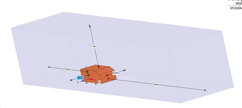
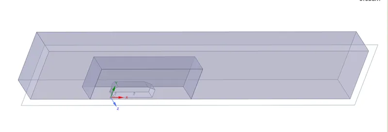
Preparing the geometry for the domain around the ahmed body. An enclosure is designed to define the flow domain around the ahmed body.
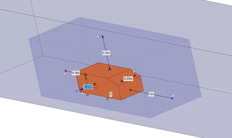
Another enclosure is designed to define the wake region inside the bigger enclosure.
The geometry is checked for interference and the shared topology is checked and the ahmed body in this case is suppressed for physics.
The geometry before interference check
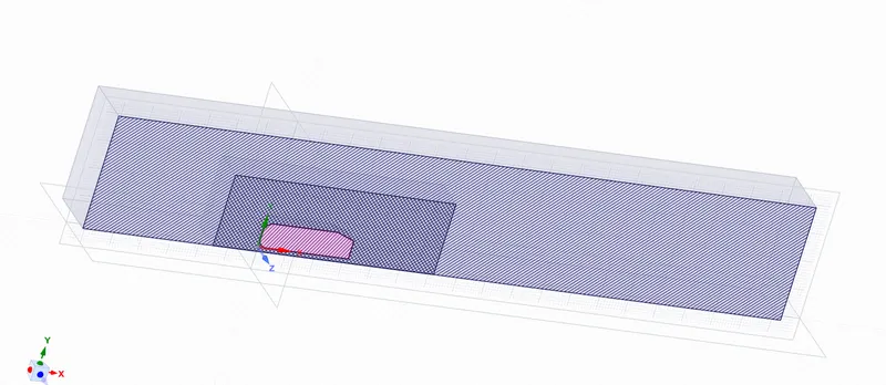
The Interference check
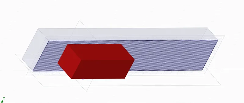
The geometry after interference check
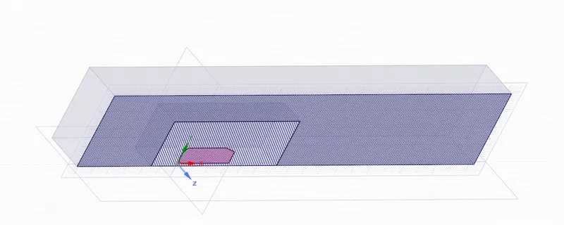
Split body command is used to split the entire geometry into half along the XY axis as the geometry is symmetric.
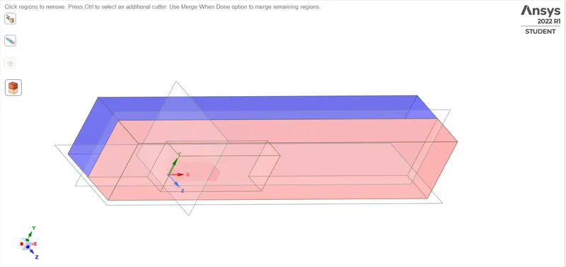
The final geometry updated for meshing:
Step 2: Meshing
The faces are named for boundary conditions as inlet, outlet, car-wall and symmetry
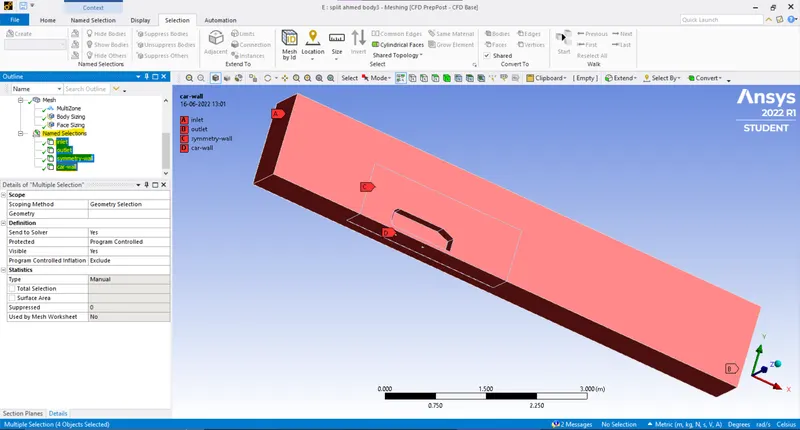
Then there are two enclosures and a body to be meshed with different preferences.
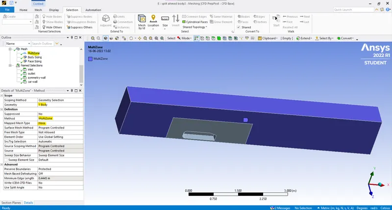
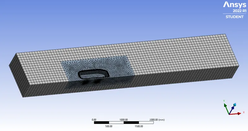
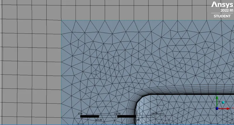
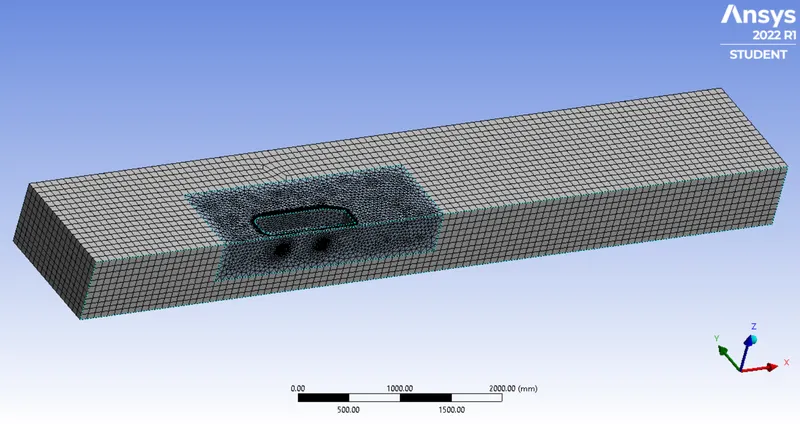
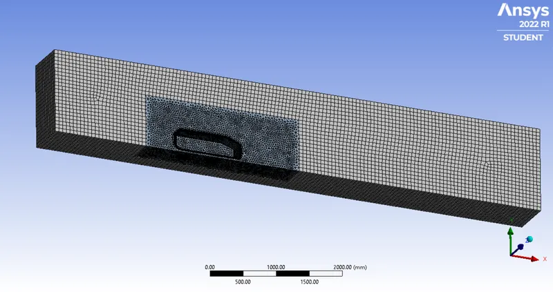
Initially a new method is inserted to the baseline mesh for the outer enclosure with multizone method, hexa type cells and the size is given between 100mm to 60mm
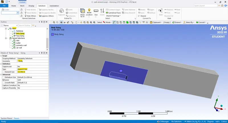
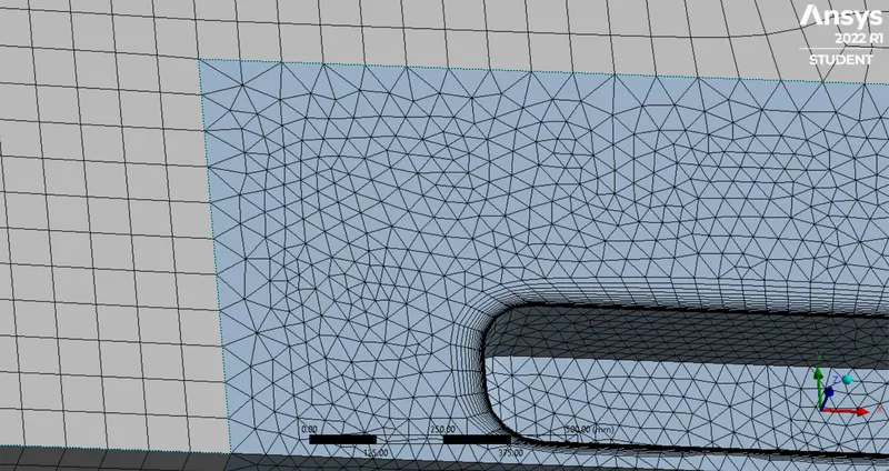
Then a body sizing method is inserted for the inner enclosure with tetrahedral type cells and the size is given between 50mm to 30mm
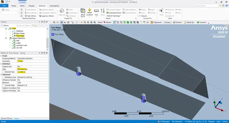
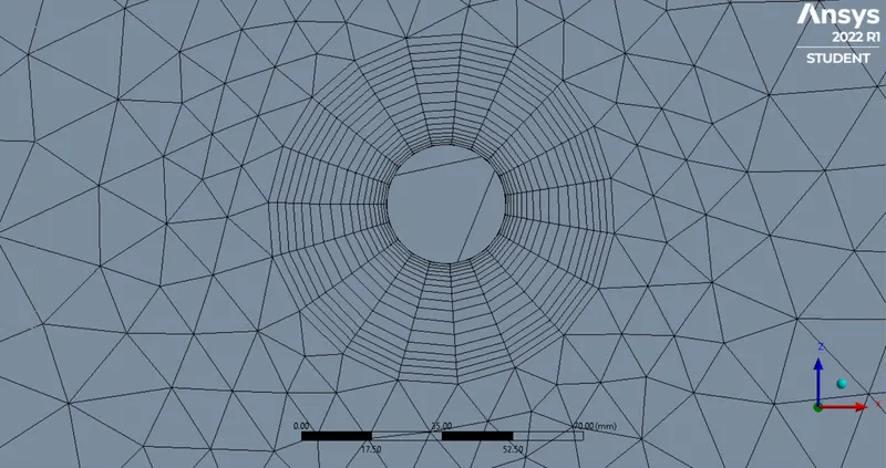
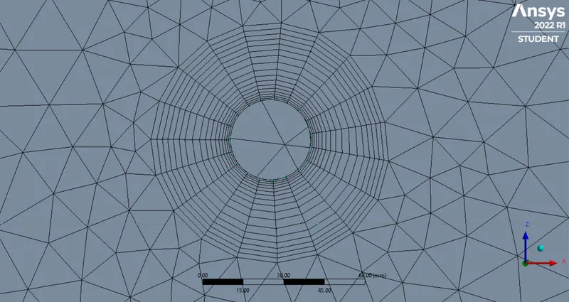
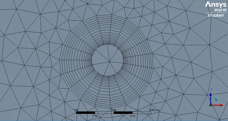
Another face sizing method is inserted for the two cylindrical faces which represent the wheel axles of the ahmed body, and the size is given as 5mm
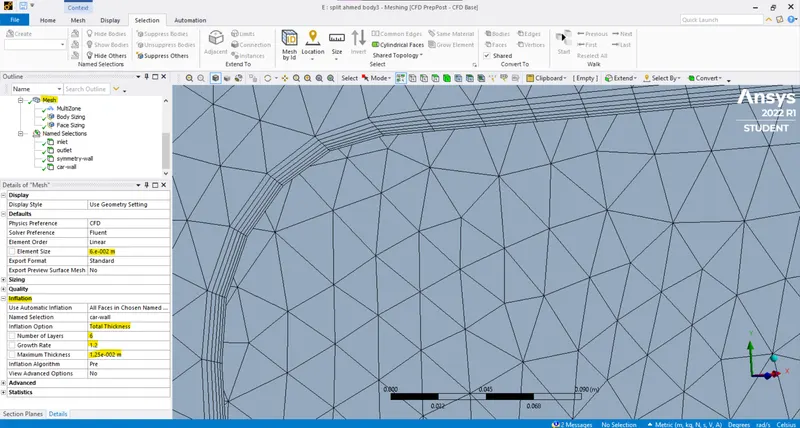
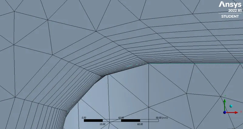
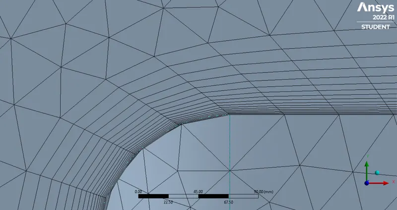
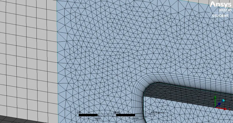
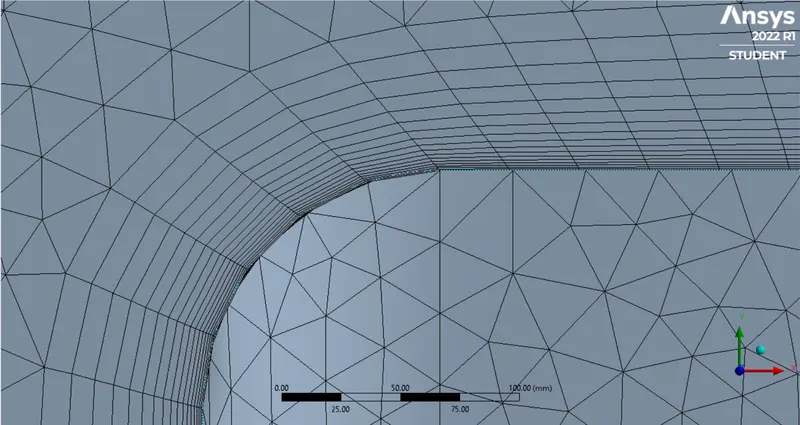
The Y+ layer thickness is calculated and 6 inflation layers are formed with total thickness 12.5mm and growth factor as 1.2
Step 3: Setup
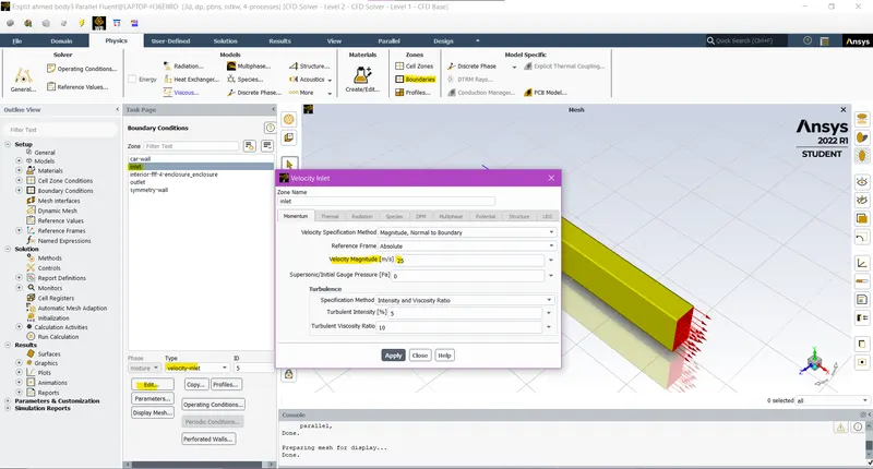
The boundary condition is given as 25m/s for inlet
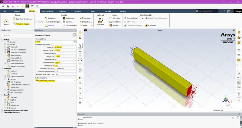
The reference values are corrected to compute from the inlet
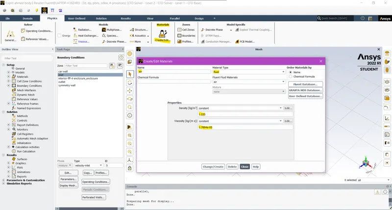
The material is set to air by default
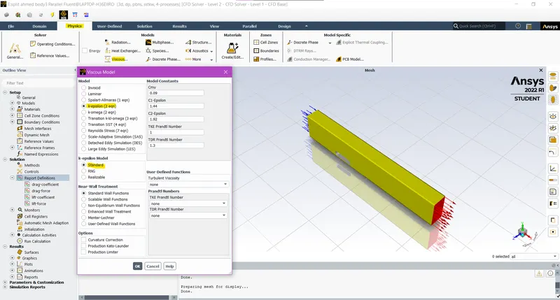
The K-Epsilon standard model is selected
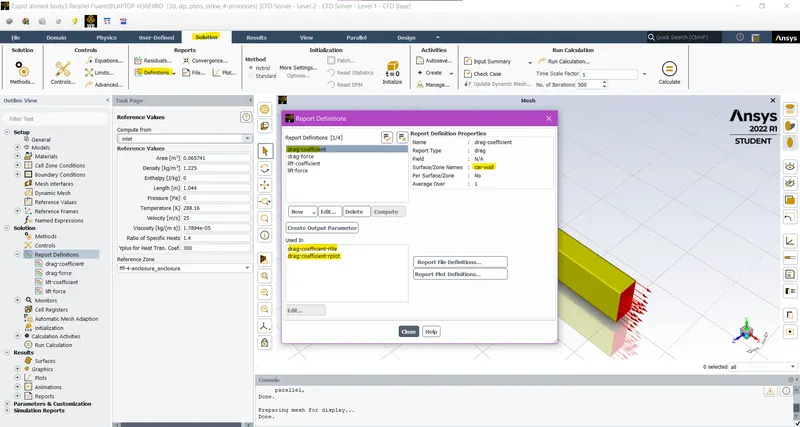
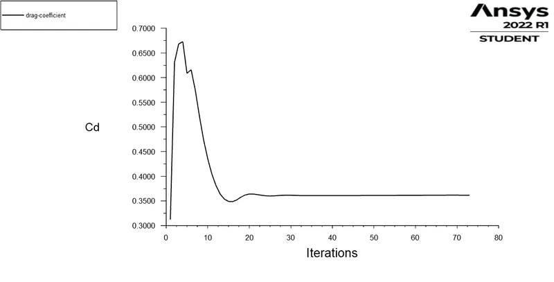
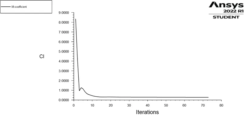
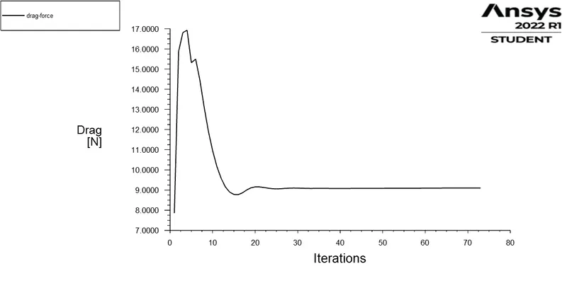
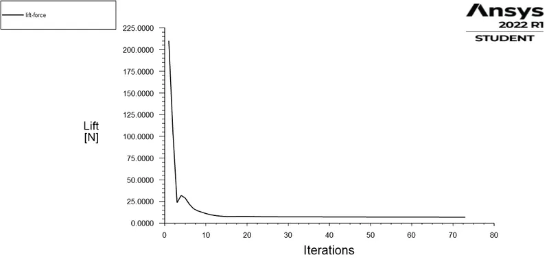
The definitions are set for drag coefficient, lift coefficient, drag force and lift force.
The hybrid initialisation is done and the solution is run for 500 iterations
Step 4: Processing results
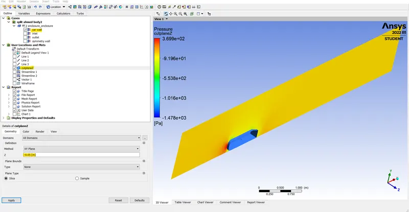
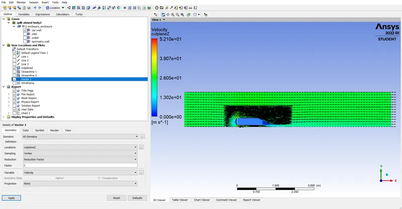
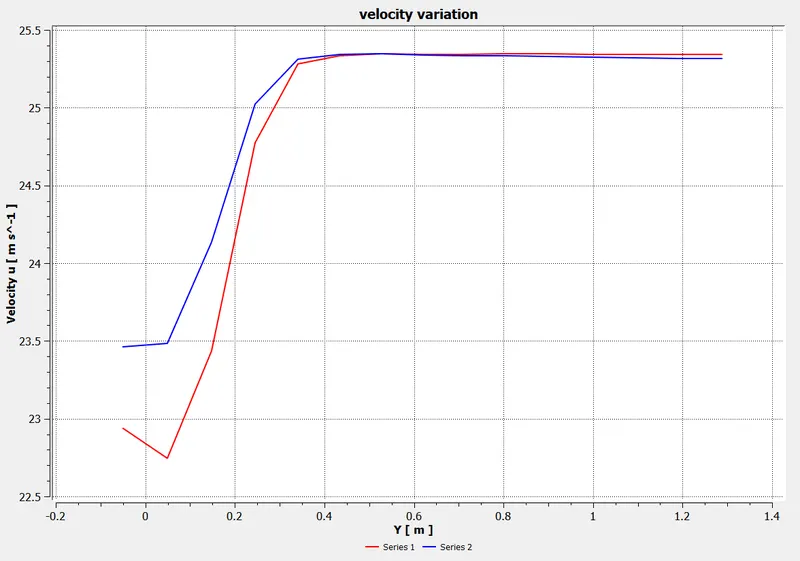
cut-plane-z: A new cut plane with dimensions XY, Z: -0.01 is defined
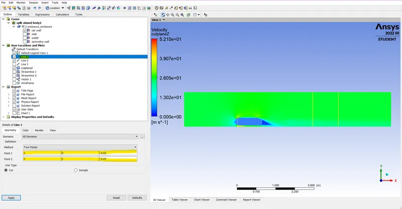
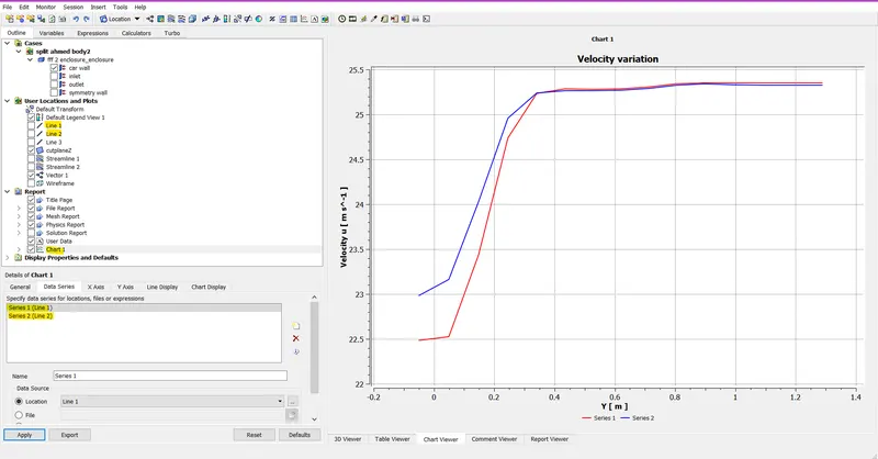
line-1: A 2 point line with points (3,0,-0.05) and (3,1,-0.05)
line-2: Another 2 point line with (4,0,-0.05) and (4,1,-0.05)
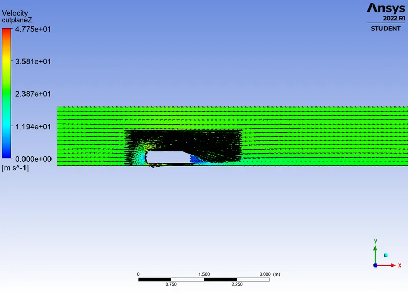
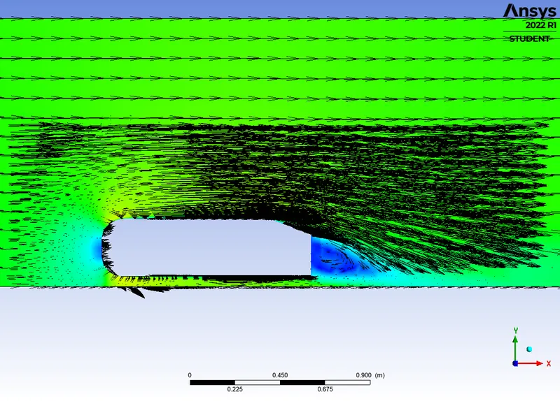
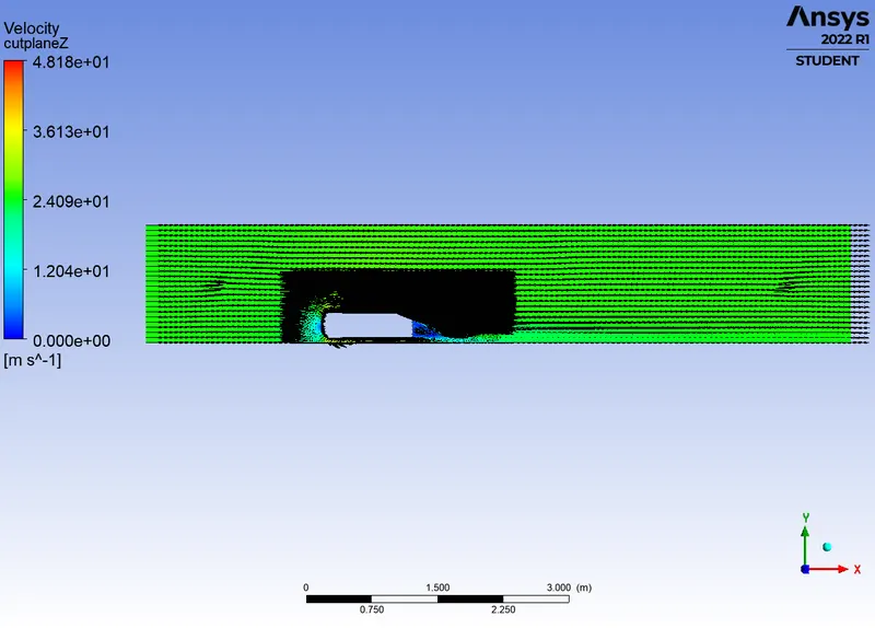
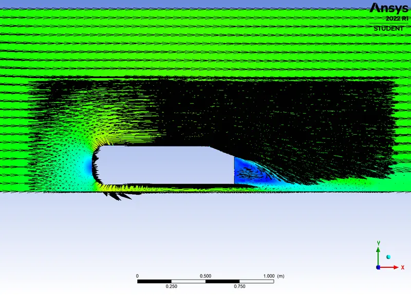
The vector plot at the cut-plane-z is plotted.
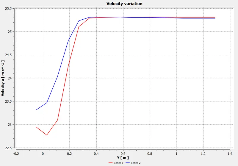
The velocity variation chart along the y-axis is plotted using the data series of the lines 1 and 2
Run Cases:
| Case 1 | Case 2 | Case 3 |
|
Hexa mesh size: 100mm Tetra mesh size: 50mm Face sizing: 5mm Inflation layers: 0.7*17*1.2 Model: K-Epsilon standard inlet velocity: 25m/s |
Hexa mesh size: 80mm Tetra mesh size: 40mm Face sizing: 5mm Inflation layers: 0.7*17*1.2 Model: K-Epsilon standard inlet velocity: 25m/s |
Hexa mesh size: 60mm Tetra mesh size: 30mm Face sizing: 5mm Inflation layers: 0.7mm*17*1.2 Model: K-Epsilon standard inlet velocity: 25m/s |
Results:
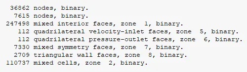
Case 1:
Mesh:
|
100mm hexa mesh
|
50mm tetra mesh
|
|
5mm face sizing
|
0.7mm*17*1.2 inflation layers
|
Plots:
|
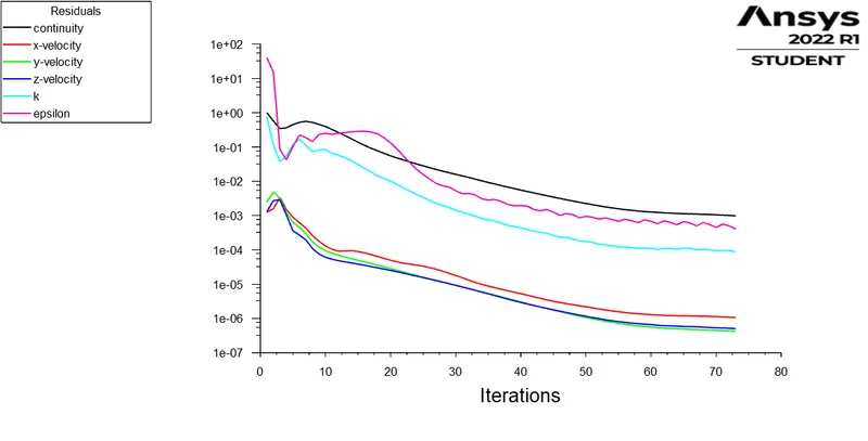
Residuals
|
Velocity variation
|
|
Co-efficient of drag
|
Co-efficient of lift
|
|
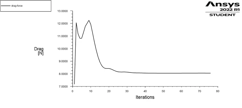
Drag force
|
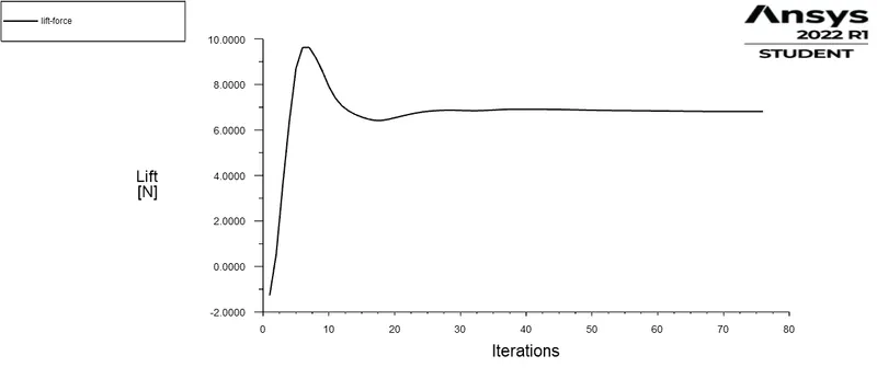
Lift force
|
|
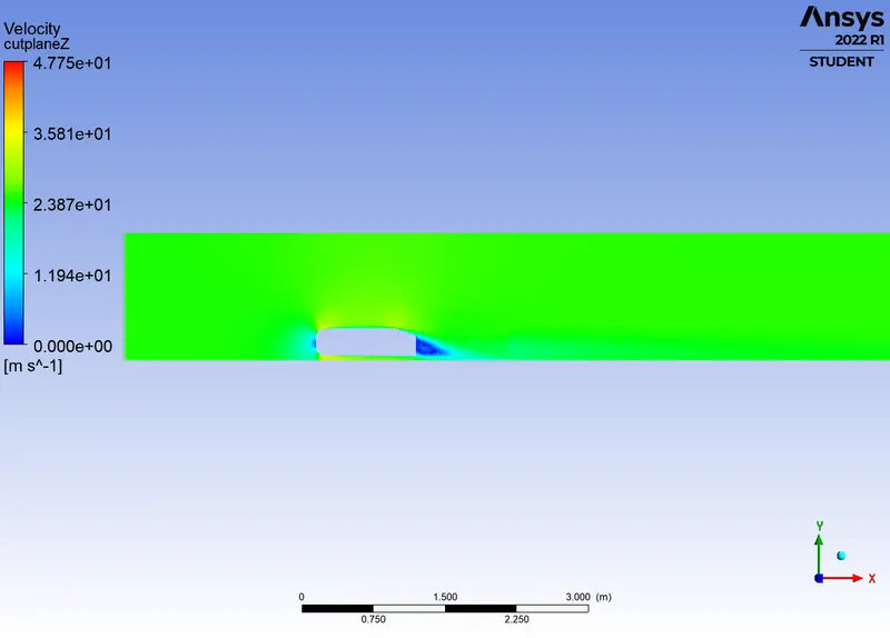
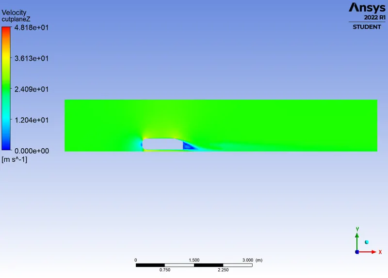
Velocity contour
|
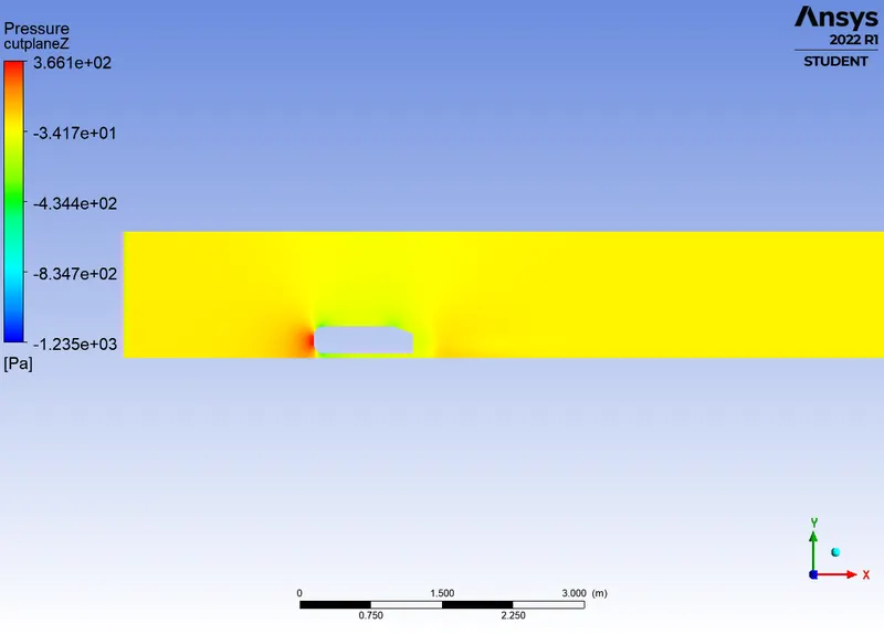
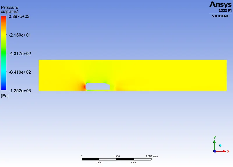
Pressure contour
|
|
Vector plot
|
Vector plot
|
Case 2:
Mesh:
|
80mm hexa mesh
|
40mm tetra mesh
|
|
5mm face sizing
|
0.7mm*17*1.2 inflation layers
|
Plots:
|
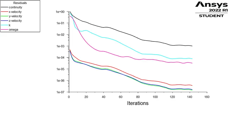
Residuals
|
Velocity variation
|
|
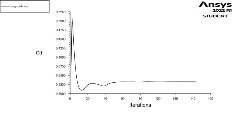
Co-efficient of drag
|
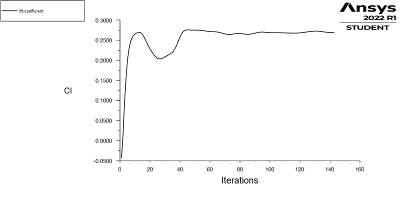
Co-efficient of lift
|
|
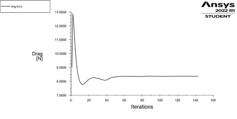
Drag force
|
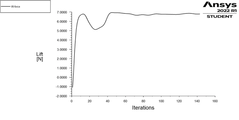
Lift force
|
|
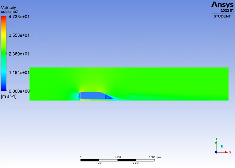
Velocity contour
|
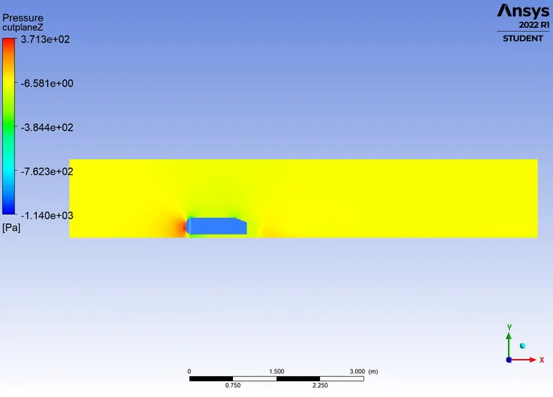
Pressure contour
|
|
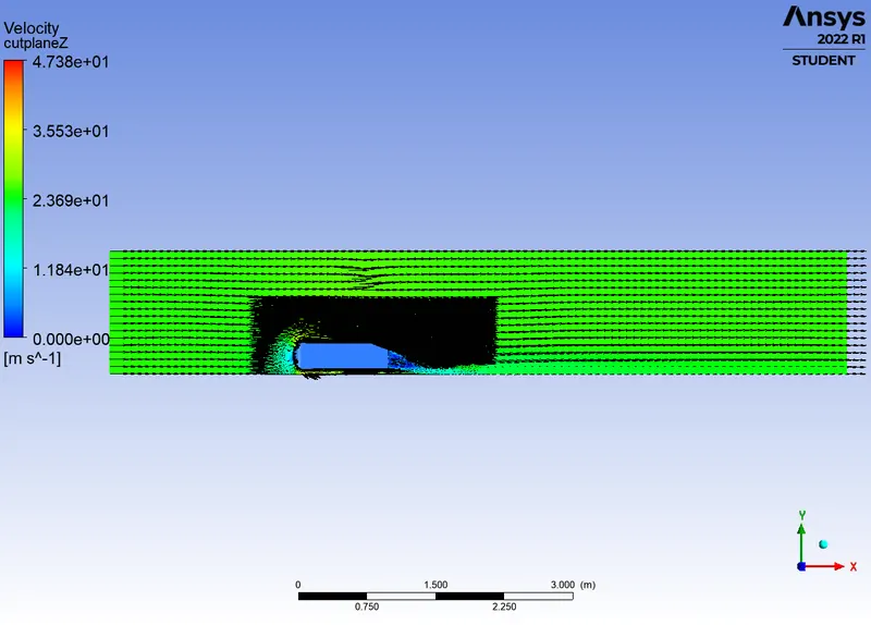
Vector plot
|
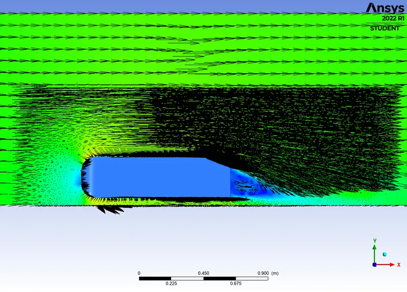
Vector plot
|
Case 3:
Mesh:
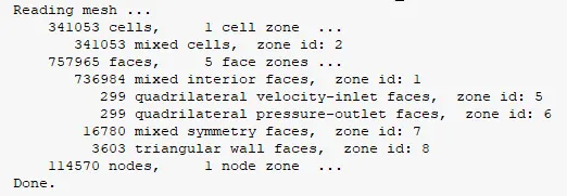
|
60mm hexa mesh
|
30mm tetra mesh
|
|
5mm face sizing
|
0.7mm*17*1.2 inflation layers
|
Plots:
|
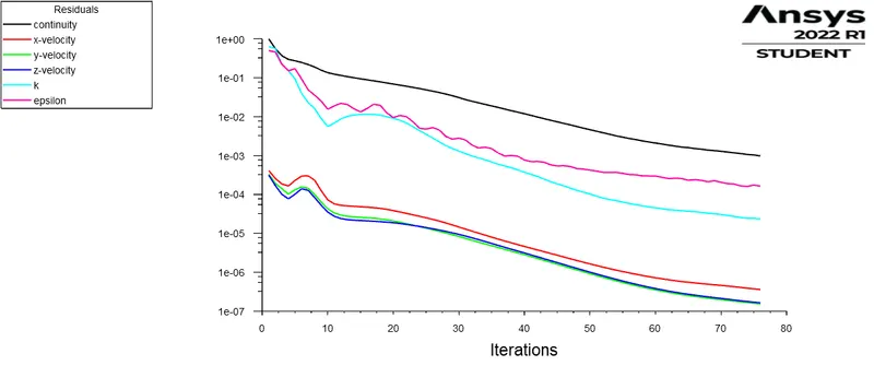
Residuals plot
|
Velocity variation chart
|
|
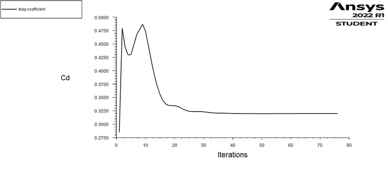
Drag co-efficient plot
|
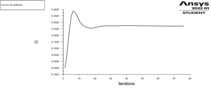
Lift co-efficient plot
|
|
Drag force plot
|
Lift force plot
|
|
Velocity contour
|
Pressure contour
|
|
Velocity vector plot
|
Velocity vector plot
|

Inference:
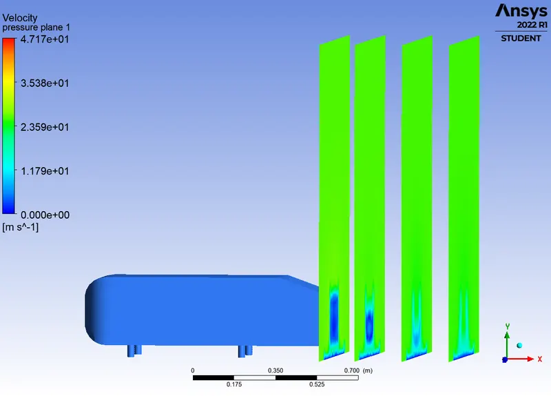
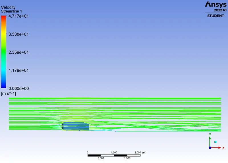
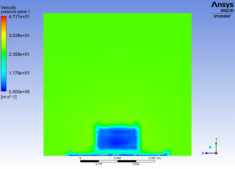
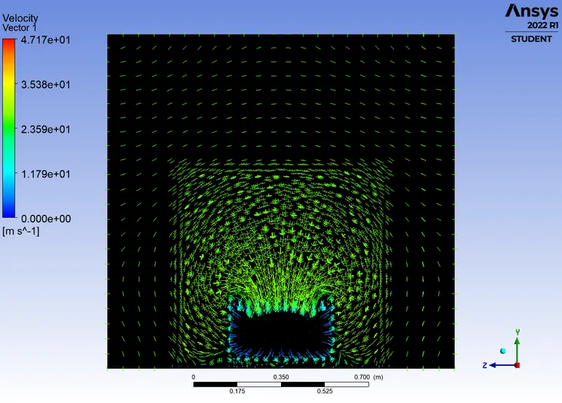
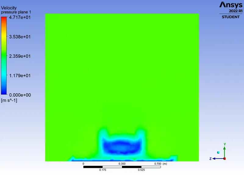
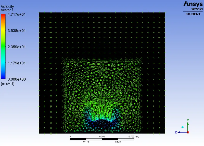
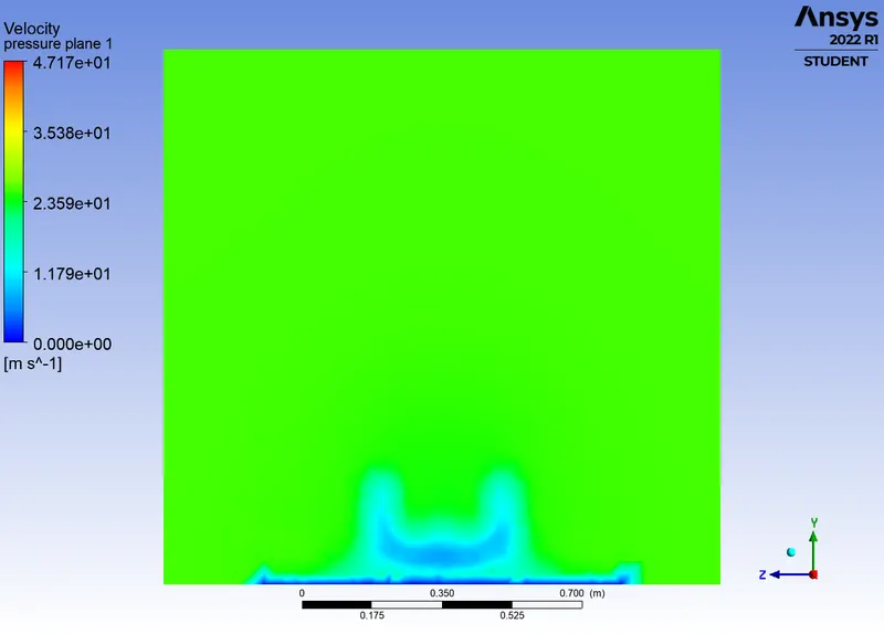
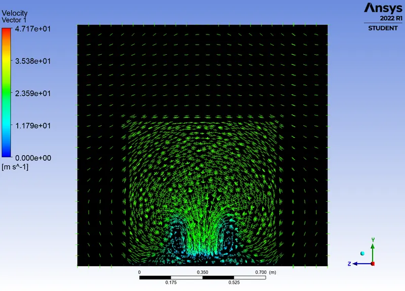
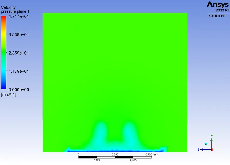
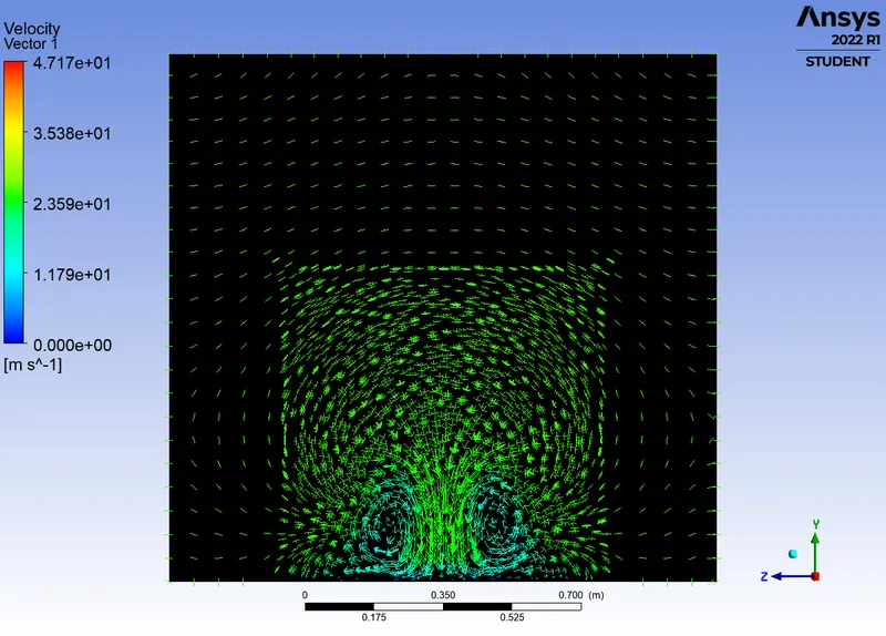
To explain the negative pressure and flow separation principles, full ahmed body is taken and analysed. Four YZ planes at certain distances from the rear of the body is placed, and velocity contours and vectors are plotted to analyse the flow separation phenomenon
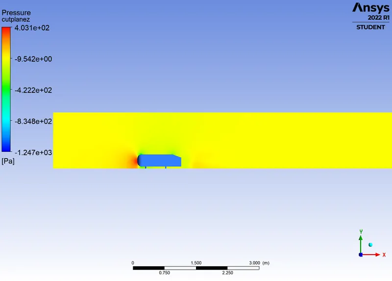
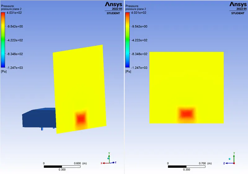
High pressure is formed at the frontal area of the body, since there is sudden loss of kinetic energy of the air, which is because of the geometry of the body.
Negative pressure in the wake region:
The vectors show circular motion or vorticity generation at the rear end of the body. The separation occurs on the upper part and also at the lower part. The particles leaving the body has some momentum just near the surface exit accomplishing the no-slip condition which means the particles with the lowest velocity is even in contact with the slope and base of the rear part. Thus the fluid particles away from the region having higher pressure gushes towards the lower pressure region creating a circular vorticity, in the wake region.
Due to the aerodynamic design of the body, an empty region or low-pressure region is created at the end of the body. The atmospheric pressure tries to fill in the region by pulling the particles, which creates a negative pressure in the region.
The wake flow exhibits a system of vortices. merging of these vortices depend upon the base slant angle. The regions of flow separation exhibit complex kinematic macro structures. Such structures in the wake, which is the major separated flow region of a vehicle flow field determines the drag experienced by the body.
Point of flow separation:
Separation of flow is said to occur when the direction of flow velocity near the surface is opposed to the direction of free stream velocity which means du/dy<0. Such a situation arises when there is a negative pressure gradient near the wall. In the direction of the flow, the pressure increases which causes decrease in velocity and creates condition for separation to occur. also skin friction co-efficient reaches the value zero. At this point the wall shear stress vanishes is called the separation point. Reverse flow takes place beyond the point of separation. Due to reverse flow, irregular eddies are formed and lot of energy is dissipated. This region is called the 'Wake'. The pressure distribution in the wake is quite different from that on the remaining boundary and this gives rise to an additional drag force on the body. Wake also leads to lateral vibration to the object which may be harmful, also large amount of K.E is lost.
In the turbulent boundary layer, some of the energy is dissipated in friction, slowing airflow velocity, resulting in a pressure increase. If the increase in pressure is gradual, the process of turbulent mixing will cause a transfer of energy from the fast moving eddies to slower ones in the turbulent boundary layer. if the rate of change in pressure is too great, for example in sharp corners, the mixing process will be too slow to push the slower air molecules moving . When this happens, the boundary layer flow stops following the contours of the surface, resulting in separation. Air particles downstream of the separation region will then move towards the lower pressure region will reattach.
| YZ planes | Streamlines view |
 |
 |
| Velocity contour view | Vector plot view |
 |
 |
 |
 |
 |
 |
 |
 |
Grid independence test:
| Number of cells | Cd | Cl | |
| Case 1 | 110737 | 0.36 | 0.277 |
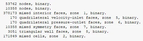
| Case 2 | 171849 | 0.33 | 0.269 |
| Case 3 | 341053 | 0.31 | 0.27 |
Conclusion:
- The grid dependency test shows, that by refining the mesh more and more, the error is greatly reduced and the Cd value approaches near to the analytical value.
- The Y+ value calculated as per the viscous model used, increases the accuracy of the velocity and pressure plots
- As the inflation layer or boundary layer thickness is adjusted, the wake region is more comfortably computed.
- An increase in slant angle would facilitate the detachment of the fluid farther from the rear end.
- With a refined mesh, the computed results of both the K-Epsilon standard and K-Omega SST model does not vary much
Reference:
1. Aerodynamics: Basic concepts and rear end application in small vehicles - A Review, by Dr.Pravin M. Ghanegaonkar and Hrushikesh M.Hiwase. IJERT,ISSN: 2278-0181
2. Kang, Nam, "Effect of approach flow condition on the wake of an Ahmed body" (2021). Electronic Theses and Dissertations. 8559. https://scholar.uwindsor.ca/etd/8559