Doorbell and Automatic temperature controller fan model in Simulink
Part1: Doorbell model
Aim: Design the doorbell model using Simulink blocks.
Objectives:
- Study working principle of doorbell system.
- Study working mechanism of doorbell system'
- Study Simulink block required for the model.
- Plotting the input and output graph.
Theory:
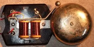
The electric doorbell is a simple circuit that triggers a sound on the completion of the circuit by pressing the button. It is this simplicity that makes the doorbell such a marvel. The simple devices in the doorbell are put the scientific principle of electromagnetism into action in a useful way. To understand the operations of an electric bell, you should first need to understand what is an electromagnet. Well, to put it in simple words, an electromagnet is basically a type of magnet in which the magnetic field is produced with the help of an electric current. When any electrical influences electromagnet it works as a standard magnet (generating magnetic fields). When the power generation to an electromagnet stops, the production of the magnetic field also stops.
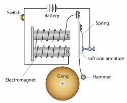
So, in an electric bell, an electromagnet forms an important part along with Armature, Spring, Armature rod, Hammer, and a Gong.
An electric source, for example, a battery can be used to power the electromagnet used in an electric bell. The electric circuit is completed by installing a push switch which you can press to generate sound in an electric bell. The switch also acts as the circuit breaker.
So once the setup is completed, when the switch is pressed, the circuit loop is complete which causes the current to flow through the circuit. The arm which strikes the gong is connected to spring at one end and an iron ball at the other end. This is called a hammer or a hammer. The arm is attached to an iron strip which is attracted to the electromagnet when the circuit is complete and the current flowing through it.
Why does this happen? It’s mainly because the magnetic field created by the electromagnet attracts the iron strip towards it when the circuit is complete. This is the moment when you hear the ringing sound since the hammer keeps hitting the gong. Meanwhile, at its rest position, the hammer is held away from the gong on account of the spring attached to its arm. This is an anchored arm.
Working Mechanism:
Now that you have an understanding of the important parts of an electric bell, the step-by-step process of the working of the electric bell is described below:
- The switch is pressed and the current flows through the circuit.
- The electromagnet is powered and generates a magnetic field that attracts the iron strip towards it.
- The hammer strikes the gong (bell).
- When the hammer strikes the gong, the contact is broken and the current stops flowing through the circuit.
- This causes the electromagnet to lose its magnetic field. The connected spring arm returns the hammer to its original rest position.
- The contact is restored and current flows through the circuit (provided the main switch is still pressed).
- The process is repeated from the beginning.
Simulink Model Study:
Blocks Used to build the Model
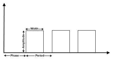
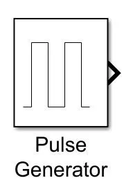
1.Pulse Generator: The Pulse Generator block generates square wave pulses at regular intervals. The block waveform parameters, Amplitude, Pulse Width, Period, and Phase delay, determine the shape of the output waveform. The following diagram shows how each parameter affects the waveform.
symbol:
Input Parameters:
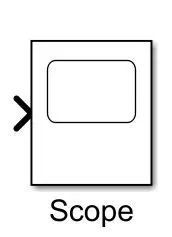
2.Scope: It is used to display the output of the signal. It has only an input port.
symbol:
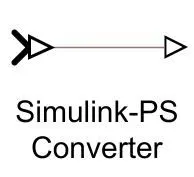
3.Simulink-PS Convertor: It is used to convert Simulink signal to physical signal.
symbol:
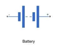
4.Battery: It is used as a source of voltage and current.
symbol:
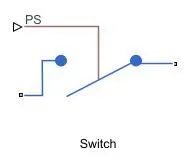
5.Switch: It is a type of switch which takes the input signal from the physical signal to allow to flow of current from the circuit.
symbol:
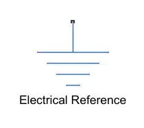
6.Electrical reference: It is used for grounding for the circuit.
symbol:
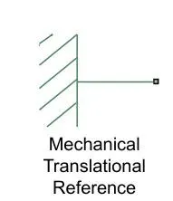
7.Mechanical Translational Reference: The Mechanical Translational Reference block represents a reference point, or frame, for all mechanical translational ports. All translational ports that are rigidly clamped to the frame (ground) must be connected to a Mechanical Translational Reference block.
symbol:
8.Solenoid: The Solenoid block represents the electrical characteristics and generated force for the solenoid in the following figure:
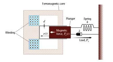
The return spring is optional. To remove the effects of this spring from the model, set the Spring constant parameter to 0.
To show the direction in which the solenoid acts, the block icon changes dynamically based on the value of the Motion direction under the excitation parameter.
symbol:
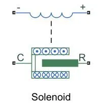
Ports:
1.+-Positive Terminal:
Electrical conserving port associated with the solenoid positive terminal.
2.-_Negative Terminal:
Electrical conserving port associated with the solenoid negative terminal.
3.C-Case:
Mechanical translational conserving port associated with the case
4.R-Plunger:
Mechanical translational conserving port associated with the plunger.
9.Ideal Translational Motion Sensor: The Ideal Translational Motion Sensor block represents a device that converts an across variable measured between two mechanical translational nodes into a control signal proportional to velocity or position. You can specify the initial position (offset) as a block parameter.
symbol:

Ports:
1.R-Rod (positive probe):
Mechanical translational conserving port associated with the sensor positive probe.
2.C_Case (reference probe):
Mechanical translational conserving port associated with the sensor negative (reference) probe.
3.V_Velocity, m/s:
Physical signal output port for velocity.
4.P_Position, m:
Physical signal output port for the position.
10.Display: It is used to display the output values.
symbol:
11.PS-Simulink Convertor: It is used to convert the physical signal to a Simulink signal.
Symbol:
Simulink Model of doorbell:
Explanation Of model:
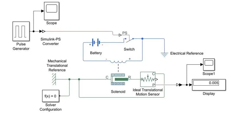
1.First up all battery model is added to circuit by battery source block.
2.Now we add a switch with taking input from the physical signal, to operate this switch we add a pulse generator whose output is converted to a physical signal with the help of a signal converter. as stated in the problem we have to give a delay of 2 seconds after each cycle, so we give phase delay as 2 seconds. We have to connect the electrical system to electrical reference i.e. grounding the circuit.
3. Now we connect the solenoid terminal to the battery and switch as shown in the model. The c port is connected to the mechanical translational reference so it is fixed. next, the R port is connected to the ideal translational motion sensor to get the output of the plunger in terms of the position of the plunger.
4. Now we connect the display to the ideal translational motion sensor with the help of PS to Simulink converter and connect this to scope which will plot the output motion of the plunger.
5.The solver Configuration block is used to specifies the solver parameters that your model needs before you can begin the simulation.
Outputs:
1.Output of Pulse Generator:

2.Output of Plunger solenoid:

Conclusion:
finally doorbell model is made in simulink for a delay of 2 sec with the help of a pulse generator. after every 2 sec the plunger will move towards the bell and circuit breaks. Once the electromagnetism of metal becomes weak the plunger again moves to its original position.
Part 2:Automatic temperature controller fan
Aim: Design the automatic temperature controller fan with the help of a thermistor in the Simulink model.
Objectives:
- Study of automatic temperature-controlled fan circuit and concept.
- Study of Simulink blocks used to design the model in Simulink
- Study of input and output required to give blocks of Simulink.
- plotting the graph of fan speed with the help of the Simulink model.
Theory:
We are modeling the automatic temperature-controlled fan with the help of a thermistor. In this project, we have some temperature range for a different time and we have a reference temperature for a fan which is 25°C. so we have to design the Simulink model such that the fan should on if the temperature exceeds above 25°C.
Working of Thermistor:
A thermistor is a kind of temperature-dependent resistor and its resistance varies depending on the temperature in its vicinity. There are two types of Thermistors- NTC and PTC.
Negative temperature coefficient (NTC) Thermistor decreases its resistance when the temperature increases while Positive temperature coefficient (PTC) increases its resistance when the temperature increases. Thermistors are bead-like resistors available from 100 ohms to 10K or more values.
Simulink Model:
Explanation of Simulink Model:
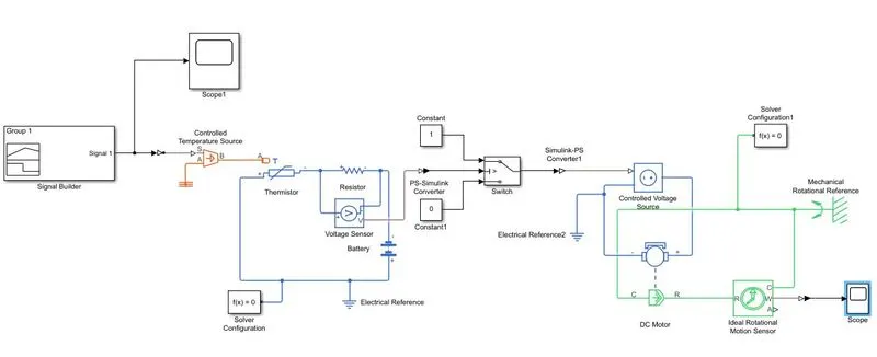
1. The first step is to set the input of temperature range for the particular time range so for that we have to give input as a graph between temperature Vs time with the help of signal Builder. We have to convert all temperatures to kelvin.
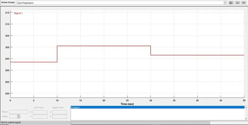
2.Now to convert Simulink signal to physical we use a converter, we define the input of the converter in kelvin. now we connect the output of the converter to a controlled temperature source. There are two input ports and one output port of the temperature source. The one input is connected to thermal reference and the output is connected to the input of the thermistor.
3.The remaining two ports are connected to the resistor and battery. Across the resistor, we connected the voltage sensor to get the output for the switch to operate.
4.To get a fan on at 25°C we have to find the threshold value for the switch at 25°C. This can be done by giving input to controlled temperature only at one contact value which is 25°C. after that we connect the output of the voltage sensor to display the value at 25°C. Now we get the value for the switch on and off, now we define the switch such that the output should be one if the temperature is greater than 25°C otherwise output should be zero.
5. Now we have completed the electrical part we have to go to our mechanical part which is fan system.
6.Now we connect the output of the switch to the controlled voltage source with the help of the Simulink-PS converter.
7.The output of the voltage source is connected to the dc motor and the dc motor inputs. Next output of the dc motor is connected to the ideal rotational sensor to get the output of the motor on-off condition.
8.All electrical and mechanical blocks are connected with their corresponding reference and solver configurations.
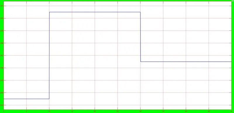
Input temperature graph:
Output:
Angular velocity of motor and on off condition graph:

Conclusion:
From the above output graph we can conclude that the fan get on for the 25°C temperature and once the temperature go below fan get automatically off. In the we can see that fan get on for range of 10-30 sec which represents 27°C temperature.