CAD modeling and rendering of Yacht
Aim: Design, cad model, and assembly of the yacht with the help of blueprint given by using Solidwork Software.
Objectives:
- Cad Modeling of the yacht by SolidWorks software.
- Learning surfacing tools in SolidWorks software.
- Assembly of Yacht in Solidwork software.
- Learning about rendering tools in SolidWorks visualization software.
Introduction:
A yacht is a sail or power vessel used for pleasure, cruising, or racing. There is no standard definition, so the term applies to such vessels that have a cabin with amenities that accommodate overnight use.
Design considerations for a cruising yacht include seaworthiness, performance, sea kindliness, and cost of construction, as follows:
Seaworthiness addresses the integrity of the vessel and its ability to stay afloat and shelter its crew in the conditions encountered.
Performance hinges on many factors, including the waterline length (longer means faster), drag in the water (narrower hull with smooth appendages), hull shape, and sail shape and area.
Sea kindliness is an indicator of steering ease, directional stability, and quelling of motion induced by wind and waves.
Multihull offers tradeoffs as cruising sailboats, compared with monohulls. They may be catamarans or trimarans. They rely on form stability—having separate hulls far apart—for their resistance to capsize. Their advantages include greater: stability, speed, (for catamarans) living space, and shallower draft. Their drawbacks include greater expenses, greater windage, more difficult tacking under sail, less load capacity, and more maneuvering room required because of their broad beam. They come with a variety of sleeping accommodations and (for catamarans) bridge-deck configurations.
The design of Yacht involves creating individual parts and assembling them concerning their proper constraints and mates.
Theory:
Process Flow chart:
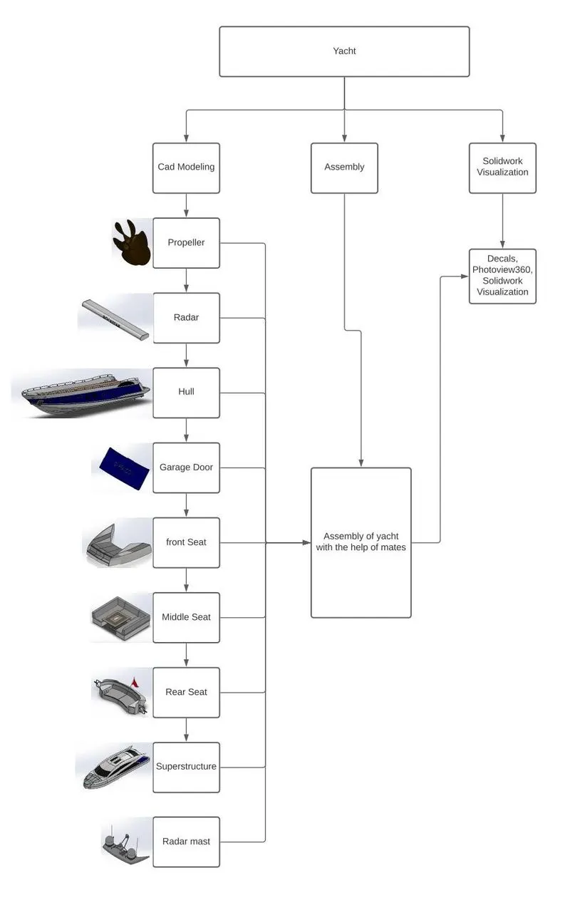
List of Parts of Yacht:
- Propeller
- Radar
- Hull
- Garage door
- front seat
- Middle seat
- Rear seat
- Superstructure
- Radar Mast
Description of all parts:
1.Propeller:
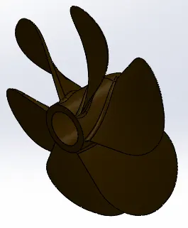
A propeller is a device with a rotating hub and radiating blades that are set at a pitch to form a helical spiral, that, when rotated, performs an action that is similar to Archimedes' screw. It transforms rotational power into linear thrust by acting upon a working fluid, such as water or air.
Features used to create the propeller:
- Sketch
- Revolve
- Loft
- Cut Extrude
- fillet
- circular pattern
Methodology :
- For designing the propeller the main hub is created by a simple sketch line and spline drawn on the front plane and extruded using the revolve option around the centerline.
- The wings are twisted parts created by sketching the two different rectangles on two different surfaces and formed into solid using the loft option.
- The shape of the wings is obtained fillet applied at the two edges on the top side.
- For inserting the shaft the hole is created by sketching the circle on the hub back end and material are removed using extrude cut option. Color is applied to the propeller for appearance as shown in the figure.
2.Radar:
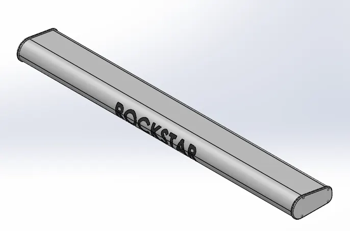
Marine radars are X band or S-band radars on ships, used to detect other ships and land obstacles, to provide bearing and distance for collision avoidance and navigation at sea. They are electronic navigation instruments that use a rotating antenna to sweep a narrow beam of microwaves around the water surface surrounding the ship to the horizon, detecting targets by microwaves reflected from them, generating a picture of the ship's surroundings on a display screen.
Features used to create the Radar:
- Sketch
- Extruded Boss/Base
- Extruded Cut
- Sketch Pattern
- Fillet
- Mirror
- Split Line
Methodology :
- By drawing the required sketch the body of the Radar was created using Extruded Boss/Base.
- By using the Sketch Pattern the four Dotted holes were created using Extruded Boss/Base and Extruded Cut.
- The Radar has a circular slot underneath which was created using the Extruded Cut.
- The other half was mirrored with the help of a mirror tool.
- The Text over the Radar was created using the Text option in sketch and then the Split Line was used to generate over the face of the radar.
- At last, the radar must be filleted around the edges of the body and also around the four holes.
- Finally, the part was saved by adding proper appearance.
3.Hull:
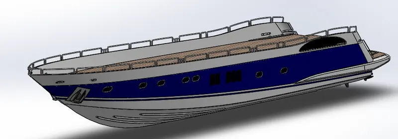
A hull is the watertight body of a ship or boat. The hull may open at the top (such as a dinghy), or it may be fully or partially covered with a deck. ... The line where the hull meets the water surface is called the waterline.
The hull of a ship is the most notable structural entity of the ship. To define the hull, it can be said that it is the watertight enclosure of the ship, which protects the cargo, machinery, and accommodation spaces of the ship from weather, flooding, and structural damage.
- The hull is a watertight body of a vessel that may be open or maybe partially covered with a deck.
- Hull has several watertight decks and bulkheads as the major transverse membrane.
- The intermediate member of the hull consists of girders, webs, and stringers.
- Depending on the structural arrangements, there may be longitudinal members for strengthening purposes.
In our model, the hull was designed along with the following parts of the Yacht,
- Aft - Referring to the aft means in or toward the back of the yacht.
- Anchor - An anchor is a heavy object that drops down into the water to keep a boat or yacht from moving.
- Beam - The beam is the widest point of a boat or yacht.
- Berth - The sleeping area of a yacht is the berth.
- Bow - The front of the yacht’s hull is the bow.
- Bridge - All of the controls of the yacht are located on the bridge, which is also sometimes called the cockpit.
- Cabin - Private rooms and living compartments in a yacht are called cabins.
- Cleat - The cleats are the metal or plastic fittings on boats where sailors attach lines.
- Deck - The part of the yacht where we can walk around outside is called the deck.
- Draft - The draft is the minimum depth of water needed for a boat to float.
- Galley - Sailors call the kitchen of a boat the galley.
- Gunwale - The gunwale is the upper edge of the side of a boat or yacht.
- Hatch - The hatch is the opening that connects the deck of a boat with the cabins underneath. Some yachts have several hatches.
- Helm - The steering mechanism of a yacht is the helm.
- Keel - The keel is the part of the hull that runs down the middle from the bow to the stern. The keel is considered the foundation or backbone of a boat.
- Knots - Knots describe the speed of a boat in nautical miles per hour. A single nautical mile is the same as a little more than 1.15 regular miles, meaning that a boat traveling at 25 knots is going almost 29 miles per hour.
- Line - The rope used on a boat or yacht is called a line. Sailors need to know how to tie proper knots in the lines to keep boats secure when they are docked.
- Port - If we are standing or sitting on a yacht looking toward the front of the vessel, the port side is the left side.
- Porthole - Windows in a yacht or boat are called portholes.
- Rig - The rig includes the sails and any devices needed to control the sails. Rigging includes equipment such as the mast, boom, yards, and spreaders.
- Starboard - When we are standing or sitting on the yacht looking toward the front of the vessel, the right side is the starboard side.
- Stern - The back of the yacht’s hull is the stern.
features used to create Hull:
- Extruded Surface
- Revolved Surface
- Lofted Surface
- Surface Trim
- Surface Fill
- Surface Knit
- Delete Face
- Project Curve
- Chamfer
- Fillets
- Reference Plane
- Split
- Split Line
- Extruded BossBase
- Extruded Cut
- Mirror
Methodology:
- The first step for modeling the Yacht was creating a blueprint of it.
- Then the blueprint was placed at the required planes, by using it first the hull was designed.
- To get the shape of the hull the projected curve was produced by drawing the required sketch using splines with the help of a blueprint.
- Then the curves were lofted to create a lofted surface and the remaining unwanted surface was trimmed using surface trim.
- Then the back portion of the hull where the propeller needs to be placed was extruded using Extruded Surface and all the surfaces created must be Knitted together to remove the gaps between the surfaces.
- Then the offset option was used and another surface was created and both surfaces were filled using surface fill to create the outer shell of the hull which will be converted into a solid body at last.
- Shell feature was used to create the front portion of the hull where the deck surface meets.
- Then the deck surface was created using Extruded Boss/Base and Extruded Cut.
- Then the required chamfers and fillets were created wherever necessary.
- All the windows and Portholes were created using Extruded Cut and Fillets were add around the edges.
- For creating the smooth edges around the berth window the reference plane was created and a circle for required dimensions was make pierced and then swept around the edge of the windows.
- The Rails at the bottom of the yacht were created using Extruded Boss/Base and the chamfers were applied on both sides.
- The Cable Rollers were created using Extruded Boss/Base and Swept Boss/Base and the head part of it was created using Revolved Boss/Base and Extruded Cut was used to cut through the extrude and a Dome was created over it.
- Helix/Spiral sketch was created to sweep the rope around the Cable Rollers.
- By using the Slot option the Rope hangers were extruded and the dome was applied and then the Linear Pattern was used to create one more.
- The window bars were created using Extruded Boss/Base.
- The staircase was created by using extruded boss/base and the hand support bar was created using Swept Boss/Base.
- The Railings around the Hull were generated with the help of a blueprint and the projected curve was produced and the railing reference was swept using Swept Boss/Base.
- The Axles for the propeller and the surfer were created using Revolved Boss/Base option and using the 3d sketch.
- The Anchors were created by sketching the first half and extruded using Extruded Boss/Base and the other half was mirrored.
- Finally, the Garage Portion was created by using Extruded Cut and the portion was saved for later use by using the Split option.
- By using the Split line option the Painting portion for our hull was split separately.
- Then the other half of the Hull and the Axle of the surfer and propeller was mirrored to form the complete hull using the Mirror tool.
- Now the part was saved by adding proper appearances and fillets.
4.Garage Door:
A garage door is a large door on a garage that opens either manually or by an electric motor (a garage door opener). Garage doors are frequently large enough to accommodate automobiles and other vehicles. The operating mechanism is spring-loaded or counterbalanced to offset the weight of the door and reduce the human or motor effort required to operate the door. Less commonly, some garage doors slide or swing horizontally. Doors are made of wood, metal, or fiberglass, and may be insulated to prevent heat loss.
Features Used to create the Garage door:
- Sketch
- Extruded Cut
- Reference Plane
- Fillet
- Shell
- Mirror
Methodology:
- The solid-body split while creating the Hull was imported to model the Garage Door.
- By using the Extruded Cut the Chamfered face for the door was created.
- Then by using the shell feature the solid body for our garage door was created and proper fillets were applied.
- Then the door holders on both sides were created using Extruded Cut.
- Then the second half of the Garage Door was created using the Mirror tool after applying the required fillets.
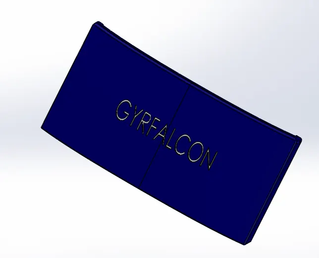
- Then the text over the garage door “HAKUNA MATATA” was created using the text option in the sketch feature.
- Finally, the part was saved by applying proper appearance.
5.Front Seat:
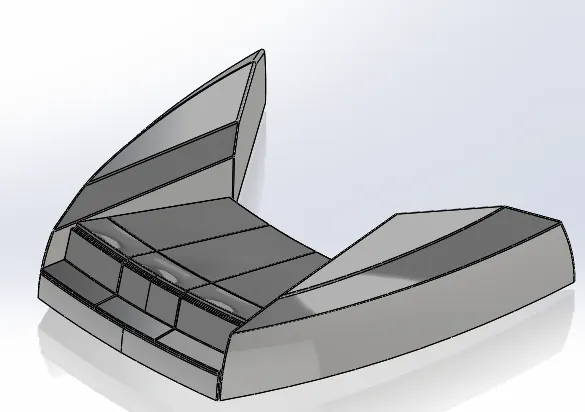
Front seats feature two connected seats that are built back-to-back from one and another. They have a built-in storage unit underneath them. Lounge seats can also fully recline right back to make it easier for you to kick your feet up and get more comfortable. The front seat in our model was placed before the superstructure and also it has sun pads to rest on it. Sun pads are a great way to reclaim lost space on our boat.
Features Used to create the Front Seat:
- Sketch
- Extruded Surface
- Lofted Surface
- Trim Surface
- Filled Surface
- Swept Surface
- Knit Surface
- Revolved Surface
- Extruded Cut
- Revolved Boss/Base
- Chamfer
- Fillet
- Mirror
- Dome
Methodology:
- The front seat of the Yacht was also created with the help of Blueprint.
- The first half was modeled and the other half was mirrored using the Mirror tool.
- The front seat was placed before the Superstructure facing the Water Feature of the Superstructure and the back end must be placed on the bow of the Yacht.
- The body of the Front Seat was modeled using Swept Surface, Extruded Surface, Filled Surface, Lofted surface, and the unwanted part was removed using Trim Surface.
- Then the four Rest Beds were created using Extruded Boss/Base and the dome was created over the face of the beds separately.
- Then the required fillets and chamfers were created with extruded thin surfaces.
- Finally, the part was saved by adding proper appearances.
6.Middle Seat:
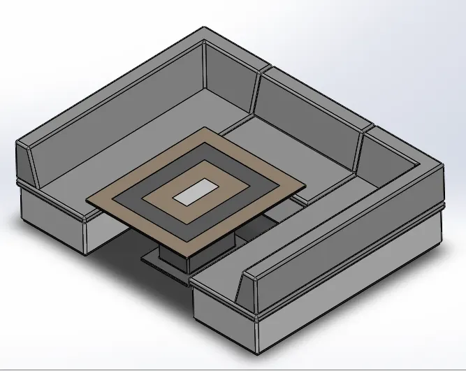
The middle seat in our model was placed just behind the superstructure. It is provided with a luxury table to dine out. It can also be used to have casual meetings with co-passengers.
Features used to create the middle seat:
- Sketch
- Extruded Boss/Base
- Chamfer
- Fillet
- Mirror
- Reference Plane
Methodology:
- The Middle Seat was created using the Extruded Boss/Base and by applying the Chamfers and fillets as required.
- All the surfaces created must be Knitted together by using the Knit Surface option.
- The Dining Table was also created using Reference Plane, Extruded Boss/base, offset Chamfers and Mirror.
- Then the second half of the Middle Seat must be Mirrored symmetrically.
- Finally, the part was saved by applying the proper appearances.
7. Rear Seat:
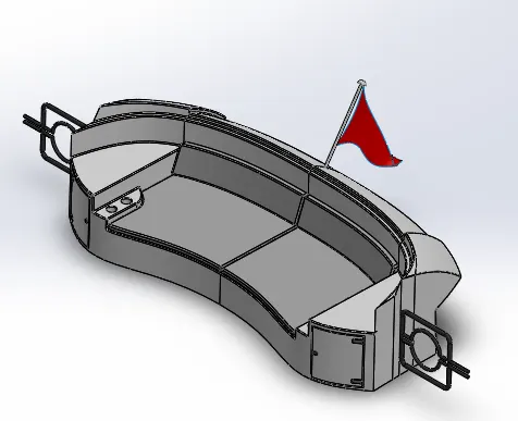
The rear seat was placed at the end of the deck surface. The rear seat consists of locker racks and steel doors for our stairs. The flag was also placed behind the rear seat since it’s the end part of our yacht. To have a nice view from the yacht while having a drink the rear seat was also provided with slots to rest the glass or mug.
Features Used to Create Rear seat:
- Sketch
- Swept Surface
- Extruded Surface
- Off-set Surface
- Filled Surface
- Knit Surface
- Ruled Surface
- Lofted Surface
- Reference Plane
- Extruded Boss/Base
- Revolved Boss/Base
- Fillet
- Mirror
Methodology:
- The main body of the Rear Seat was modeled using Swept Surface, Off-set Surface, and the remaining portion was trimmed using the Trim Surface tool.
- By using the Reference Plane the Seats were created with the help of Lofted Surface, Surface Trim and Extended Surface.
- The Flag Post was created using Revolved Boss/Base and the Flag was created by drawing the required 3D sketch and then the 3D sketches were lofted to form the Flag.
- The Tail Lamps were created by using Extruded Boss/Base, Fillets, and Mirror tool.
- The Steel Gates For Stairs was designed by using the reference plane and the Swept Surface.
- To remove the gaps the all the Surfaces must be Knitted together using Knit Surface.
- The required fillets and chamfer were created before mirroring the second half using the Mirror tool and after mirroring the uncreated areas were filleted again.
- Finally, the part was saved by adding appropriate appearances.
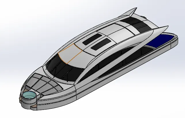
8.Superstructure :
A superstructure is an upward extension of an existing structure above a baseline called ground level and it usually serves the purpose of the structure's intended use. A superstructure is a decked structure on the freeboard deck, extending from side to side of the ship.
Features Used to create the superstructure:
- Extruded Surface
- Swept Surface
- ruled Surface
- Knit Surface
- Trim Surface
- Extend Surface
- Filled Surface
- Lofted Surface
- Revolved Surface
- Fillet
- Chamfer
- Project Curve
- Reference Curve
- Convert Entities
- Split
- Split Line
Methodology:
- The deck surface from the hull was imported and the superstructure was modeled over it.
- The side surface of the Superstructure was created by using Extruded Surface, Lofted Surface, Filled Surface, Trim Surface, and Knit Surface.
- The Front Side of the Superstructure was designed to have four rest beds which were created using Extruded Boss/Base, Fillets, and Dome.
- The front edge of the superstructure was provided with a Water Feature which was created using Extruded Boss/Base, Extruded Cut, and filled with a water appearance.
- The Windshield was created by Extruded Cut and the wipers were created by using a 3D sketch and reference plane with the help of Swept Boss/Base.
- The Portholes for the Superstructure were created by using Extruded Surface, Trim Surface, and Extend Surface.
- Ruled Surface was used to fill the left-out edges.
- The Back Doors of the Superstructure was created using Extruded Cut, Fillets, and Reference Plane.
- Then all the surfaces generated were Knitted together to form a solid body.
- The Superstructure consists of two surface bodies and five solid bodies.
- One of the surfaces was the Deck Surface the other one was used to place the Radar Mast so it was renamed as Radar Mast reference Surface.
- Then the other half was mirrored and the proper fillets and appearance were added and finally, the part was saved.
9. Radar Mast:
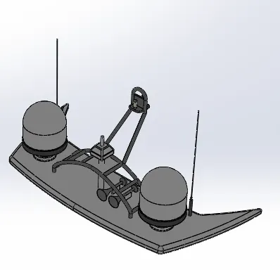
A mast is a vertical ship structure mounted on top of the bridge and forward of the forecastle towards the ship’s bow. It accounts for the support platform for the ship's derrick and holds necessary equipment such as radars, navigation light, and ships horn in case of the foremast. They are made of high tensile steel with added rigidity based on the size of derricks it holds. Other than that a ship's main mast is also used to hoist ships' flags.
Out of different parts of the ship, the main job of the mast is to hold necessary equipment such as radar receivers, navigation lights, ships' horns, flags, and derricks in some cases.
Features used to create the radar mast:
- Sketch
- Extruded Boss/Base
- Lofted Boss/Base
- Revolved Boss/Base
- Swept Boss/Base
- Reference Plane
- Projected Curve
- Fillet
- Mirror
- Dome
- Shell
Methodology:
- The first half of the Radar was Modelled with the help of a blueprint and then the other half was mirrored with the help of the Mirror tool.
- The body of the Radar was created using Extruded Boss/Base and Revolved Boss/Base.
- The antenna for the radar was also created using the Extruded Boss/Base.
- The lampstand along with the connecting rod was created using the Swept Boss/Base and Mirror tool.
- The lamp was created by using the projected curve and then the curve was swept using swept boss/base.
- The horns were created using the Revolved Boss/Base, Dome, and Shell.
- Then the fillets and chamfers were applied wherever necessary.
- Finally, the part was saved by applying appropriate appearances.
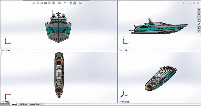
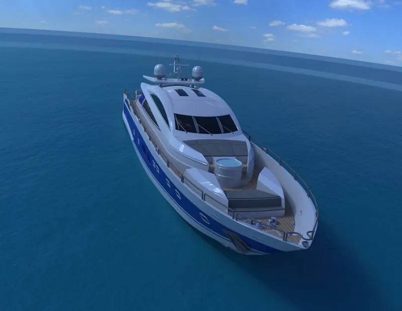
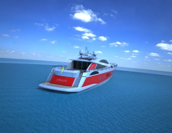
Images of Yacht:
1.
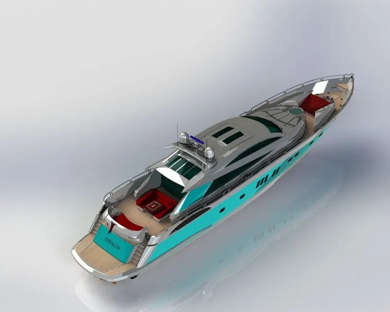
rendered images:
Conclusion :
Learned about surface tools, made assembly of all parts. Done rendering of the yacht.