Odd Shaped Enclosure design using NX sheet metal
Aim: Design the Sheet metal parts from solid bodies or null bodies in NX sheet metal software.
Objectives:
- Learn about tools used to convert solid bodies to sheet metal bodies
- Learn about different features for sheet metal design.
Introduction:
In this, we are creating a sheet metal body from solid bodies or null bodies. We are creating sheet metal from the model because sometimes we are provided with input as a cad model. Sometimes it is easier to make a model first and convert it into sheet metal.
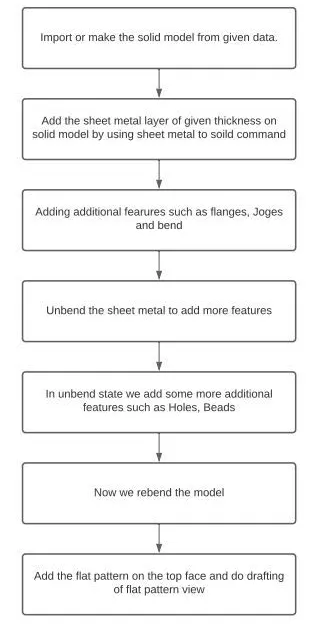
Flowchart:
Tools and Features used while designing:
1.Sketch: We used the sketch command and drawn the model sketch on the selected plane.
2.Extrude: This command is used to convert the sketch into solid bodies by defining extrude length.
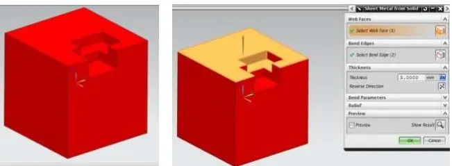
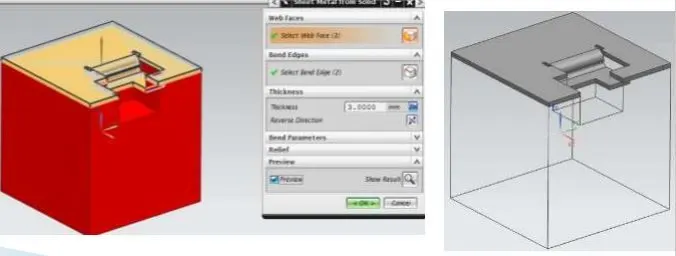
3.SHEET METAL FROM SOLID: Builds a sheet metal model that takes its shape from a collection of planar faces of a solid.
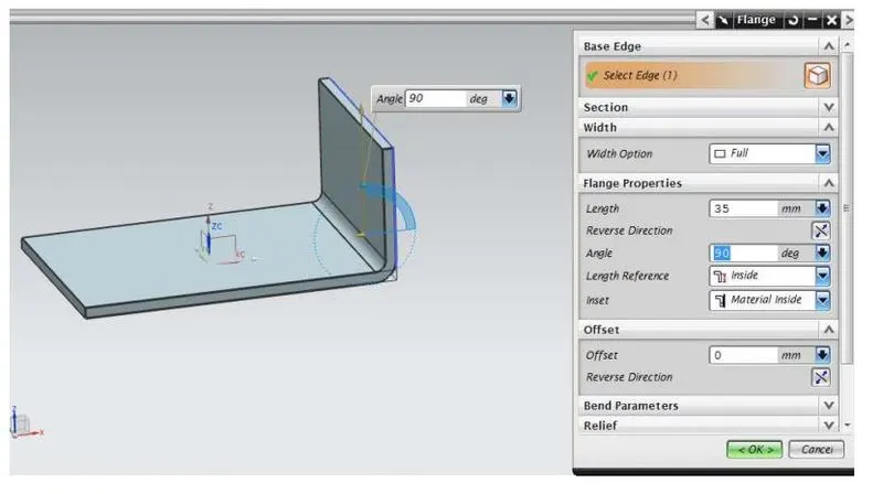
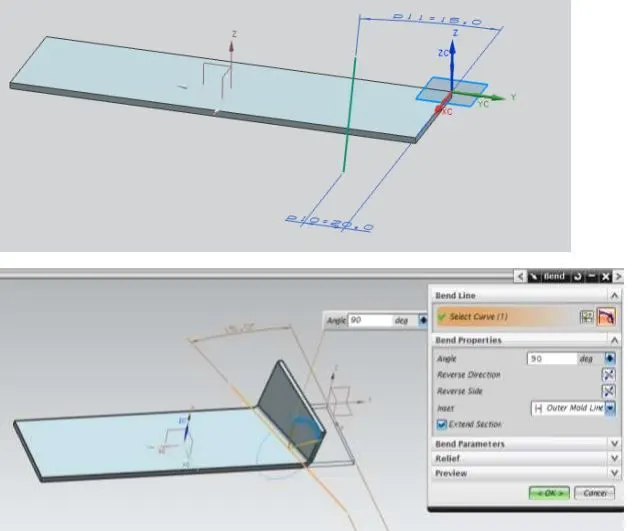
4.FLANGE: Adds a flange to an angle to a planar face and adds a bend between the two.
5.JOG: Modifies the model by lifting material on one side of the sketch line, adding a flange between the two sides.

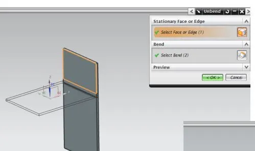
6.UNBEND: Flattens a bend.
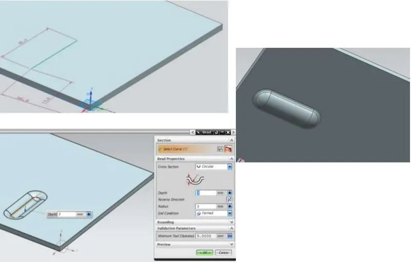
7.BEAD: Lifts a material along a counter of the sketch that simulates stamping a tool.
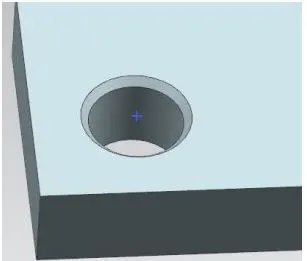
8.Hole: used to create a hole on one or more solid bodies in a part or assembly with an option for counterbored, countersunk, and threaded.
9.REBEND: Restores a bend
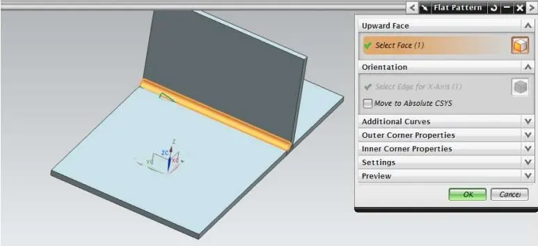
10.FLAT PATTERN: Creates flat pattern feature from the formed sheet metal part.
Images of Cad model:
1.Front View:
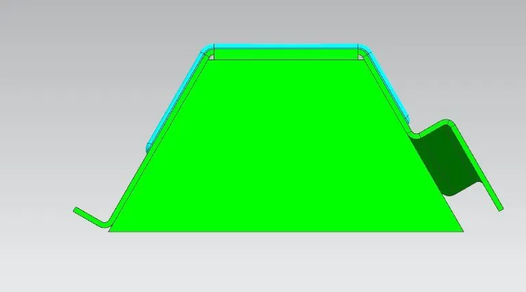
2.Left Side:
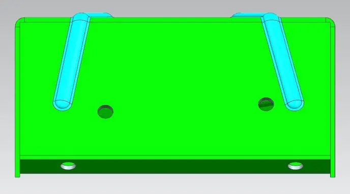
3.Right Side:
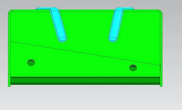
4.Top View:
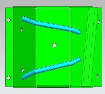
5.Bottom View:
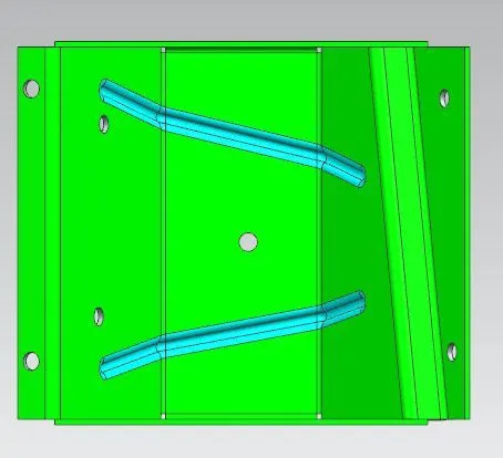
6.Isometric View:
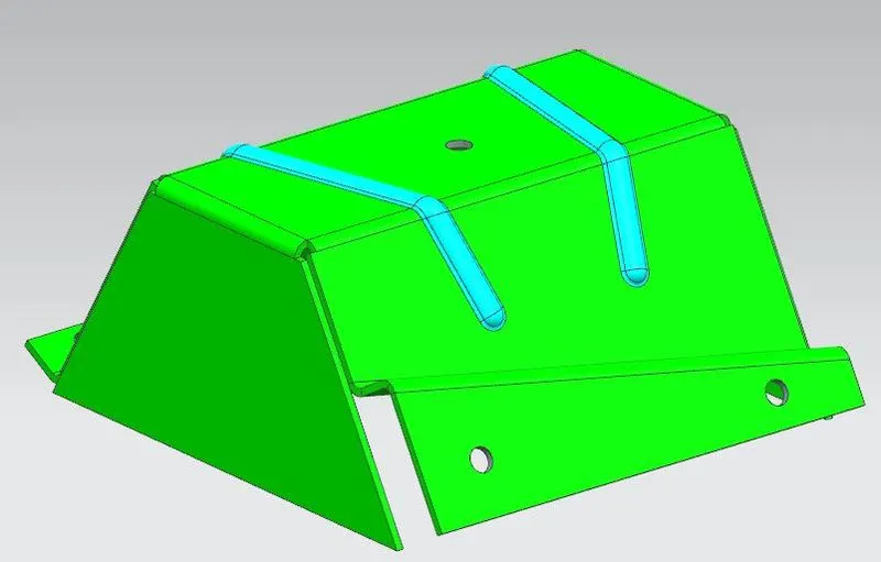
7. Drafting Image:
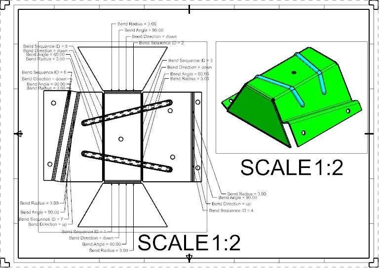
Conclusion:
From this project, we learned how to make sheet metal parts from the solid models by using sheet metal from solid command in NX software and also added some additional features to the model and drafting of the sheet metal model.