Bracket design using NX sheet metal
Aim: Design of the sheet metal Bracket using industrial standard in NX software.
Objectives:
- Study about industrial standard parameters used for sheet metal parts.
- Study about Bead and Holes used in Sheet metal design.
Introduction:
In this report, we are designing the sheet metal part from given drafting of thickness 3mm. Adding bead feature to the part in such a way that its stiffness should increase.
Flowchart:
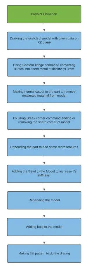
Tools and features used to model Bracket :
1.Sketch: We used the sketch command and drawn the model sketch on the selected plane.
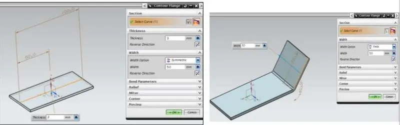
2.Contour flange: Creates a base feature by extruding a sketch along a vector, or adds material by sweeping a sketch along an edge or chain of edges.
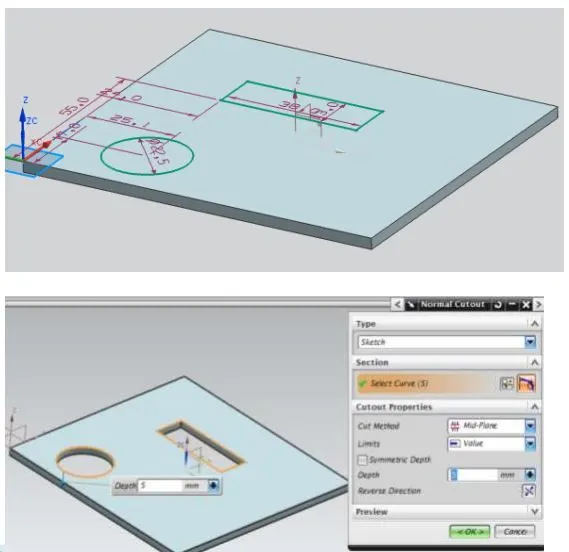
3.Normal Cutout: Cuts the models perpendicular to the sketch.
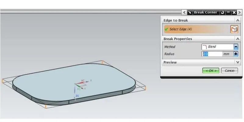
4.Break Corner: Rounds a sharp corner.
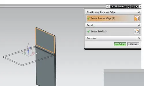
5.UNBEND: Flattens a bend.
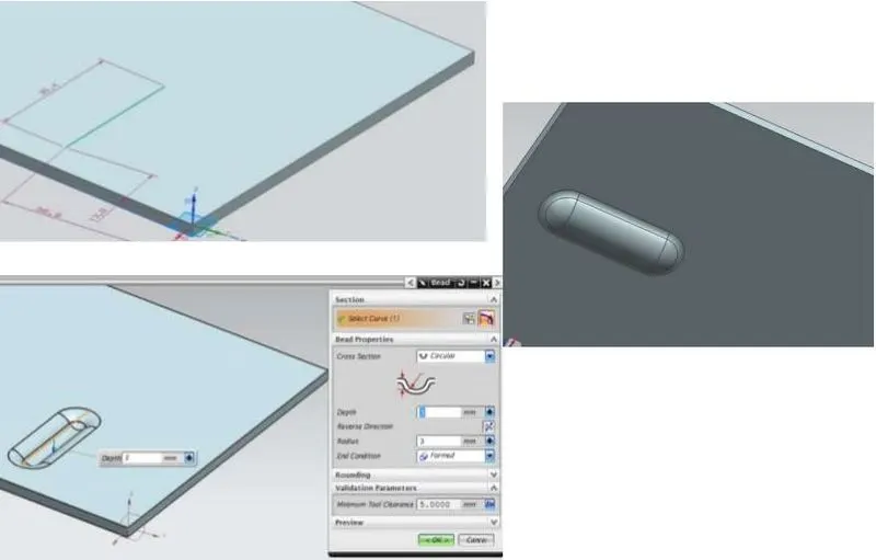
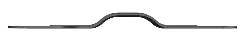
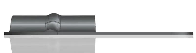
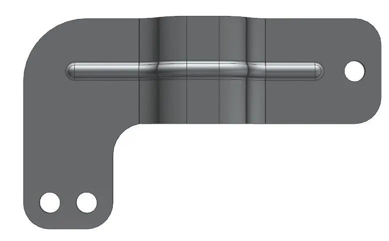
6.BEAD: Lifts a material along a counter of the sketch that simulates stamping a tool.
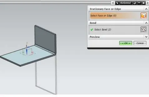
7.REBEND: Restores a bend.
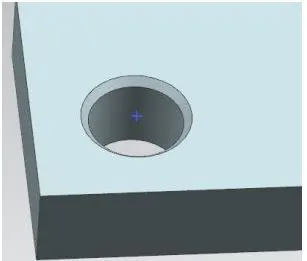
8.Hole: used to create a hole on one or more solid bodies in a part or assembly with an option for counterbored, countersunk, and threaded.
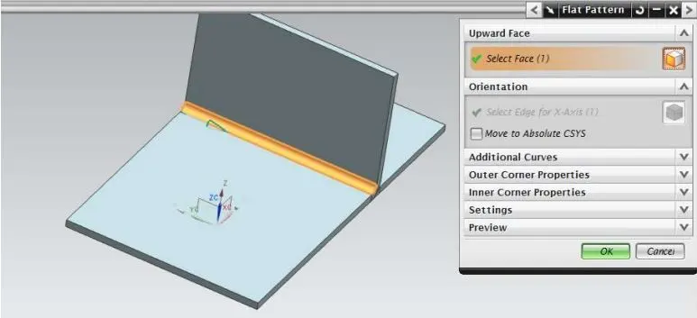
9.FLAT PATTERN: Creates flat pattern feature from the formed sheet metal part.
Images of the model:
1.Front View:
2.Side View:
3.Top View:
4.Bottom View:
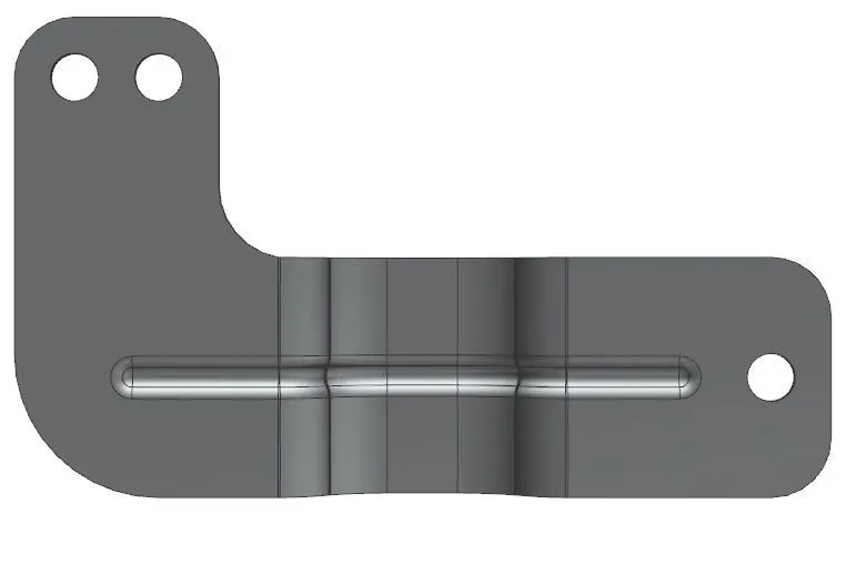
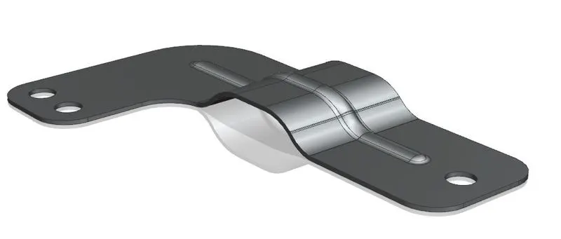
5.Isometric View:
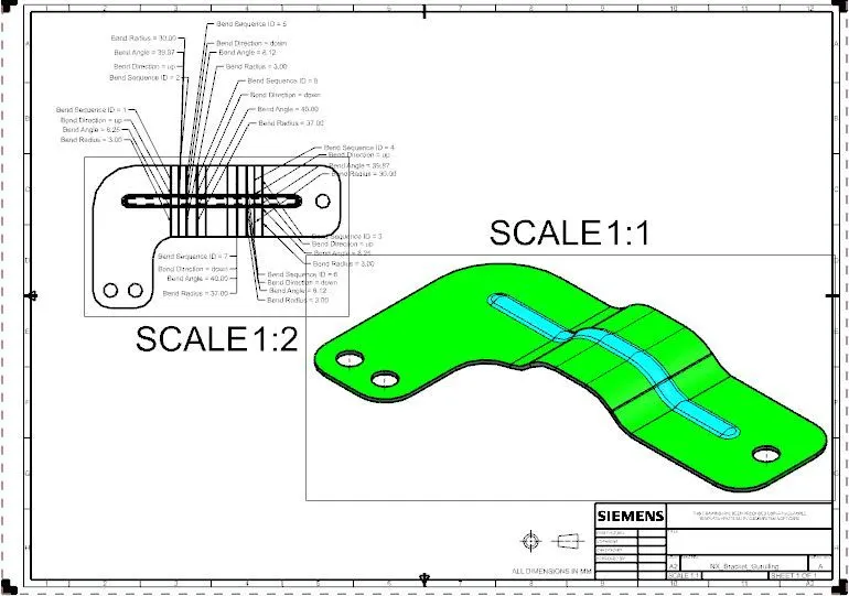
6.Drafting:
Conclusion:
From this project, we learned about parameters used to design sheet metal parts. Also learned that we can increase the stiffness of the sheet metal parts by adding a bead to parts.