Simulink Model for Washing machine and Gear shifter
Part1: Washing Machine Model.
Aim: Design of washing machine model in Simulink with the help of a chart block.
Objectives:
- Learn about washing machine working mechanisms according to state conditions.
- Learn how to apply the state condition of the washing machine in the Simulink environment.
- Learn about different blocks used in the Simulink environment.
Theory:
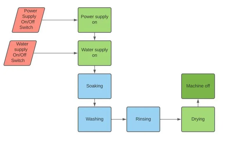
As we know the washing machine has four processes which are as follows:
1. Soaking: In this process, the water and detergent are added and clothes are kept in a mixture for a specified time so that clothe should absorb this mixture so that during washing it will be easy to remove the dirt particle from the clothes.
2. Washing: During the wash cycle, the machine uses agitation to mix the water and detergent, as well as to move the clothing around the tub--and against other clothing--to clean the load. Top-loading washing machines often contain an agitator in the middle of the tub to move the load in alternating directions, while front-loaders rely upon the rotation of the entire tub to provide the agitation necessary for cleaning. The duration of the wash cycle varies among washer types and the setting is chosen by the user. The wash cycle for heavy cleaning (for tougher jobs) will last longer. Light cleaning cycles are shorter in duration.
3.Soaking: Rinsing the load is usually a multi-step procedure. First, the soapy water must be spun from the clothing and washtub. During the latter minutes of the purging, freshwater is sprayed into the tub to rinse the clothing. The rinse cycle uses intervals of spraying and spinning to force the soapy water and detergent out of the washer. A final stage of agitation with plain water is the last step in rinsing and the beginning of the final step: spinning.
4.Drying: Warm air flows to the laundry, causing moisture to evaporate from the fabric. In the process, the drum rotates slightly, which leads to shaking of the products and, as a result, uniform drying. After the heated air, supersaturated with steam, undergoes a cooling procedure. Moisture condenses and overflows into a separate tank. Some models of modern washer-dryers allow the user to customize the drying process. The owner can optimize the procedure, focusing on their own preferences and wishes.
Flowchart of the process:
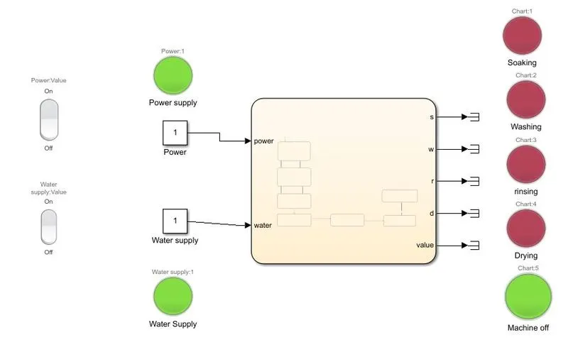
Simulink model of washing machine:
Explanation of the model:
1. There are two inputs we are providing one is for power supply and another one for water supply. we are using constant which are connected to the rocker switch which we have to manually do on and off so that it can on and off the signal. These two-input are also connected to two lamps which turn green when the signal value is 1 i.e. input is on otherwise it turns red if the signal value is 0 i.e. input is off.
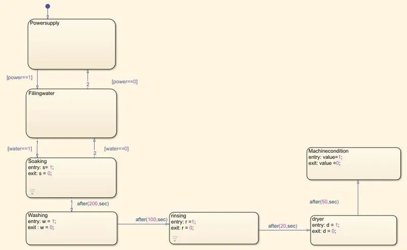
2.Now we have connected these inputs to the charts block which contains seven states which are as follows:
a. Power Supply: This is an input state which is connected to a constant block that can be controlled by a rocker switch. This gives input to the next state such that is system should run only if the power supply is on otherwise the system should no run the logic,
b.Water Supply: Most of the washing machine has automatic water control system but in this case, we are giving water supply state manually by using rocker switch as shown in the above diagram. The output of this water supply state is such that if and only if the water supply is on then it continues to the next state otherwise it stops the machine at the water supply state and turns the lamp to red color.
c.Soaking: Now if the power and water supply both are on then the process moves to the next state which is soaking. We move to the next state after 200 sec.
d.washing: After soaking the next step is washing which is for 100 seconds. To do washing for 1oos we connect the output of washing state to next state by giving delay time with the help of after(time, sec) to the output of washing state
e.Rinsing: For rinsing, we use the next new state with entry value 1 and exit value 0 for a delay time of 20 seconds which is connected to the next state.
d Drying: After rinsing we use drying state for a delay time of 50 seconds with entry value 1 and exit value 0 and at the last it is connected to machine off state where the machine gets off automatically.
f. Now in chart logic, we define all the input and output which we have to connect in Simulink.
e. Now we have five outputs in which four are process cycle and the last one is machine off state. this all outputs are connected to lamps which turns on if the output value is 1 to green color otherwise if out[ut is 0 it turns its color to red.
Chart Logic:
Output:
1. When power and water supply are On all states are done and the machine OFF lamp turns to green
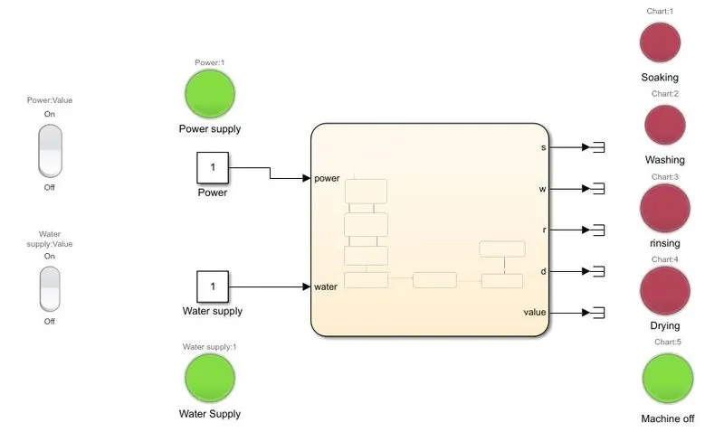
2.When the water supply is of the machine off lamp turns red because no process cycle is done.
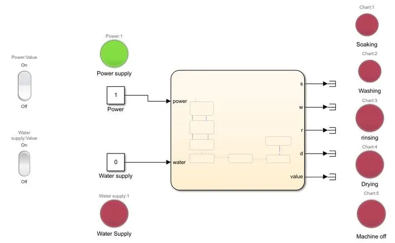
3. When the power supply is Off then no process states are on
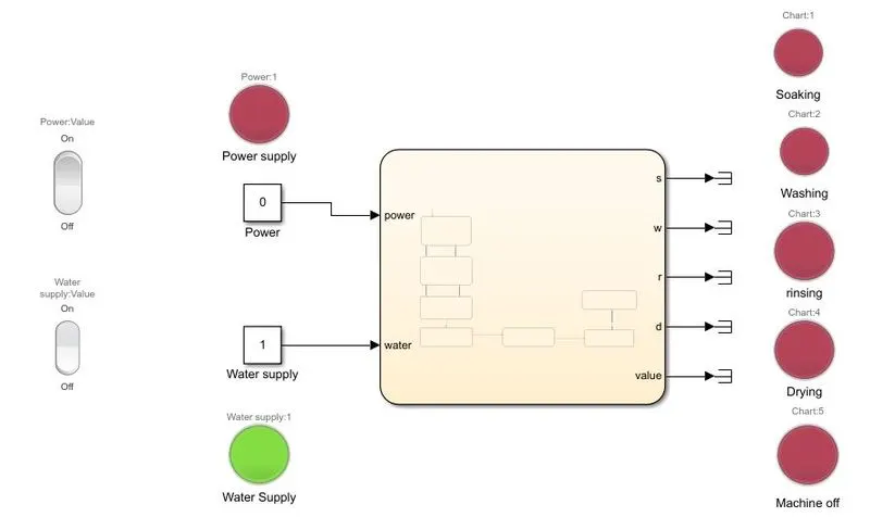
Conclusion:
from this, we can conclude that the washing machine is going to do all four cycles if both power and water supply is on, if anyone's input is off then no process is going to happen. so with the help of the Simulink chart block, we can define the states of logic without doing so much programming in Matlab.
Part2: Simulink model for the gear shift
Aim: Design the gear shifter of the vehicle for a given input velocity by using Simulink chart blocks by Stateflow vise.
Objectives:
- Study the Gear shifter mechanism for the vehicle.
- Study about the Stateflow of the gear shifter according to the change in velocity.
- Study the Simulink chart block for the gear shift model.
Theory:
As we know that in an automatic gear mechanism the gears shift according to the velocity of the vehicle. In this project, we are building the gear shift logic for five gear mechanisms which can be changed according to the velocity input.
Given Input and output conditions:
| Speed Range(Kmph) | Gear |
| 0 to 15 | 1 |
| 16 to 25 | 2 |
| 26 to 40 | 3 |
| 41 to 60 | 4 |
| above 61 | 5 |
We are using the above data to create the Stateflow of the Gear shaft by using chart block in Simulink.
Simulink Model:
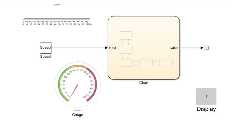
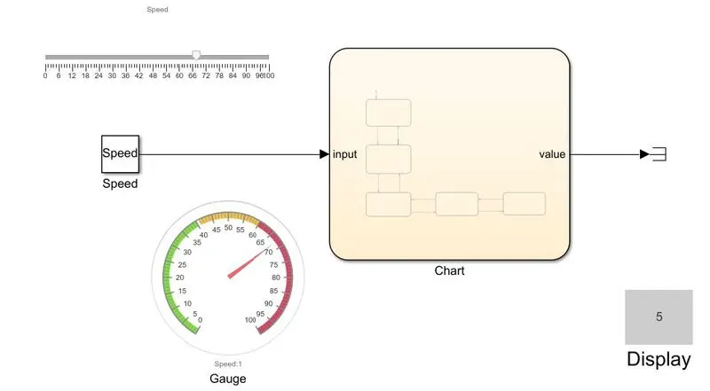
Explanation of Simulink model:
1.To make the logic of the model we use a chart block from the library. The logic is contained output as a gear number and for input, we are using speed with constant block.
2.The constant block is defined with the variable called speed in the model workspace and it is connected to the slider dashboard.
2. As we know we are giving input with the help of a slider which can be varied during a simulation run with the help of a slider, to the slider we are giving input from the signal builder.
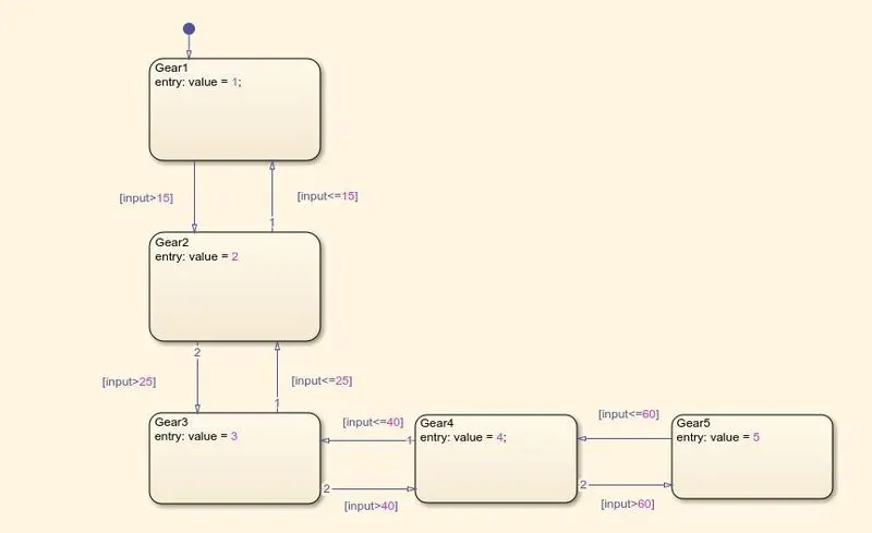
3.Now we have input no we have to define the logic for shifting the gear according to the change in speed for that we use chart block. In chart block In the first state, we define the output of the gear shift number and give condition like if the input is greater than the defined speed then shift the position to the next gear else speed is less than or equal to the defined speed then shift the gear to the previous position like that we do this condition to the all the state for given 5 positions of gear shift.
chart model:
4.Now to display the input and output we use dashboard blocks such as for input speed we use to gauge and in that gauge we define the color for input speed and this gauge is connected to the input line of the chart block.
5. for output we use to display dashboard block to the gear shift number.
Output:
1.for speed from 0 to 15 the gear number 1
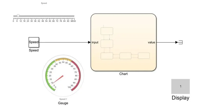
2. for speed from 16 to 25 the gear shift number is 2
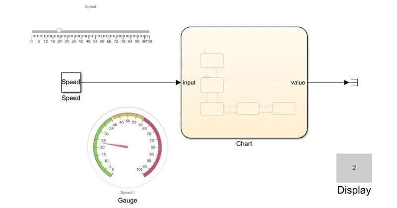
3. for speed from26 to 40 the gear shift number is 3
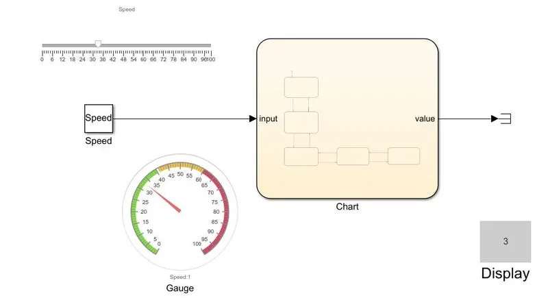
4. for speed from 41 to 60 the gear shift number is 4
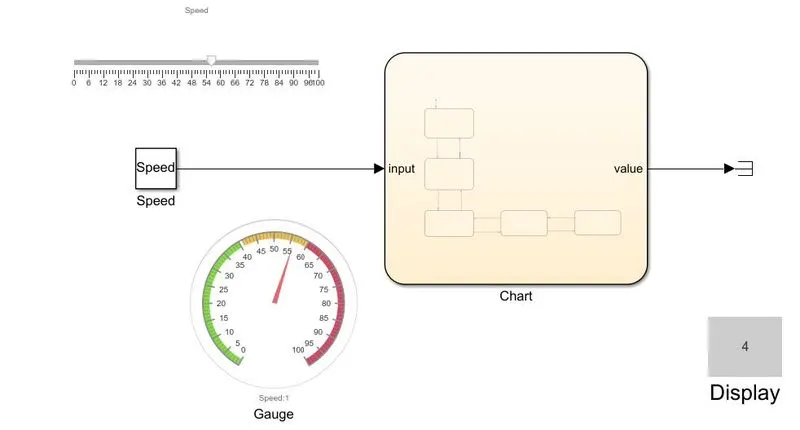
5. for speed above 60 the gear shift number is 5
Conclusion:
So we have learned that we can use the Simulink for real state conditions with only defining conditions, input, and output by using chart block. Also learned how to implement the logic and state conditions for the Gear shifting mechanism.