Design and assembly of the Hood according to the EURO-NCAP rules.
Aim: Design and development of the inner panel of the hood of the car according to the industrial standard and according to the manufacturability and assembling it with other parts of the hood in the NX software.
Objectives:
- Learn about the inner panel, outer panel, Hinges, striker parts used in the hood of the car.
- Learn about EURO-NCAP rules to design the hood of the car.
- Study about joining method used to join the inner panel and outer panel.
- Study how to fix the hinge and striker position concerning each other.
Workflow for the Hood Design:
1.Study about given master sketch of the inner panel and outer panel model and the hood of the vehicle:
2.Study about different manufacturing process which can affect the design:
3.Study about standard rules about safety and norms made by EURO-NCAP for the design of the HOOD of the vehicle:
4.Design the inner panel according to the outer panel:
5.Decide the mastic points in the inner panel
6. Do hemming o the outer panel:
7.Decide the position of hinges and striker on an inner panel and make emboss of them.
Theory:
1.Master sketch of inner panel :
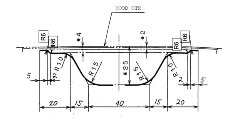
Given the thickness of the inner panel and outer panel:
- Outer Panel Thickness = 0.75mm
- Inner Panel Thickness = 0.75mm
- Reinforcement Thickness = 1.5mm
Introduction about Hood:
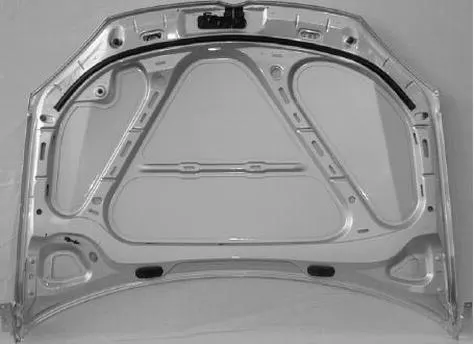
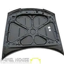
The Hood is an important component of the front portion of the car which is used for many purposes. Hood is used to decorating the car and add a luxurious look. Hood is made aerodynamic in shape to reduce air effect. Hood is generally used to cover the car engine, radiator, and many other parts, therefore Hood must be designed in such a way that all the maintenance parts should be easily accessible and it should give a minimum impact of external disturbance on the engine. When a car comes across any accident from the front portion, most of the time Hood system gets damaged. In this report, we are designing the hood with consisted the inner panel, outer panel, hinges, and striker in the NX software according to the EURO-NCAP rules given for pedestrian impact of the head on the hood. We are also going to study different joining methods used to join the inner panel and outer panel of the hood. some design of the inner panel of the hood is shown below:
2.The manufacturing process used for the HOOD manufacturing:
We are considering the metal materials for the inner panel and outer panel using a stamping manufacturing process for the inner panel and different joining methods to join the inner panel and outer panel.
1.Inner panel and outer panel manufacturing by stamping method:
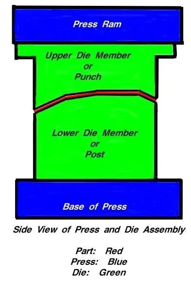
Metal stamping is the act of forming, trimming, embossing, flanging, piercing, or restriking a metal blank (usually steel sheet metal). It's strongly associated with the automobile industry, simply because each car has many parts that can be made from steel. Outer car panels, like hoods and fenders, are common examples of parts made using metal stamping processes.
A large car panel normally requires three or more dies to complete the operations necessary to make it. These machines are designed with cost considerations and safety at the fore. Next, when designs are finished and approved, the actual machines are built. The size of the machines will depend on the presses that will be employed. Some dies can be enormous in size, like a die built for forming a large SUV's hood. Some are also mechanical marvels, accomplishing multiple tasks with each downward stroke of the press it's attached to.
Process flow of the Stamping:

Disadvantages of forming process:
a. SpingBack effect:
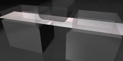
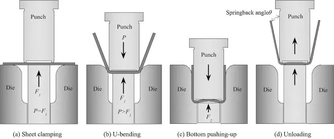
Springback is the geometric change made to a part at the end of the forming process when the part has been released from the forces of the forming tool. Upon completion of sheet metal forming, deep-drawn and stretch-drawn parts spring back and thereby affect the dimensional accuracy of a finished part. The final form of a part is changed by springback, which makes it difficult to produce the part. As a result, the manufacturing industry is faced with some practical problems: Firstly, prediction of the final part geometry after springback, and secondly, appropriate tools must be designed to compensate for these effects.
2.Joining method used to join the inner panel and outer panel:
a.Hemming:
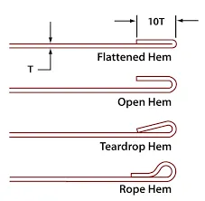
Hemming is a metalworking process that involves rolling the edge of sheet metal over and onto itself, essentially creating an area of two layers. During this process, the edge of sheet metal is folded over. The two newly formed layers then lie flush with each other.
Sheet metal is available in a variety of gauges. The gauge, of course, refers to the thickness of sheet metal. High-gauge sheet metal is thicker than low-gauge sheet metal, which can make it difficult to manipulate using processes like hemming. With the right tools, however, manufacturing companies can hem sheet metal by bending and rolling the edge over and onto itself.
Primary types of hemming, including the following:
b.Spot welding:
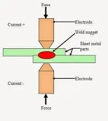
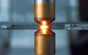
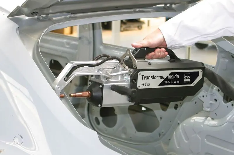
Spot welding sheet metal involves the use of the electric resistance welding technique to bring parts of sheet metal together into one fabrication assembly. When spot welding thin metal, the main objective is to avoid warping, burn-through, and excessive heat affected zone (HAZ) while ensuring the weld produces enough mechanical strength for the operation. The heat-affected zone is basically a physical witness during the spot welding process which may consist of small burn marks on the sheet metal. It would also sometimes be visible as a small indent on the surface of the sheet metal fabrication in which the sheet metal has melted and fused together under the pressure of spot welding tip. These indents however can remain untouched on components that do not require a cosmetic surface.
c.Pulling rivets:
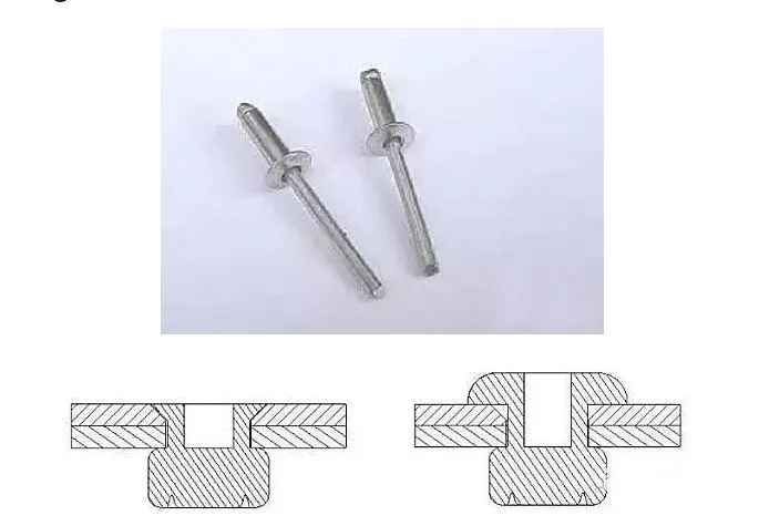
The riveting is carried out in the hole corresponding to the two parts, and the rivet gun is used to pull the rivet to expand and deform the outer rivet sleeve, thereby fixing the two parts.
So there are so many methods are available to join the two sheet metal parts of car body panels but we are using the hemming method to join the inner panel and outer panel due to following reasons:
- We don't get any penetration of welding spots on the outer panel.
- The outer panel doesn't have any holes and uneven surfaces due to the hemming process so the aesthetic is better and, aerodynamic and stress distribution forces are minimum.
Now we have decided on the manufacturing process for the inner panel and outer panel so according that we have to design the Hood parts now after this, we have to consider the pedestrian impact criteria according to the EURO-NCAP(European new car assessment program).
3.pedestrian impact criteria according to the EURO-NCAP(European new car assessment program);
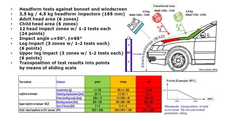
1. The most important safety requirement to be considered while designing the Hood is the frontal collision requirements for the adults and child head. Most pedestrian accidents occur within city areas where speeds are moderate. The head, the lower body, and the legs are amongst the most frequently injured body regions. To estimate the potential risk of head injury in the event of a vehicle striking an adult or a child, a series of impact tests are carried out at 40 km/h using an adult or child head form impactor. Impact sites are then assessed and the protection offered is rated as good, adequate, marginal, weak, or poor.
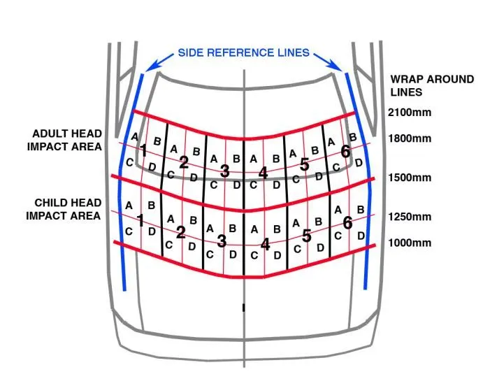
As we can see in this above diagram which shows the impact zone for child and adult head so we have to design the inner panel such that there should be minimal contact between head and inner panel, so we have to cut some inner panel sheet in such a way that the strength should not decrease and there should less impact on the head.
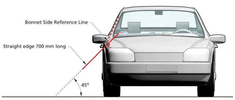
Determination of the bonnet side reference lines:
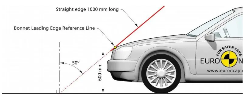
Determination of the Bonnet Leading Edge Reference Line:
So by considering all these safety parameters we have to design the inner panel and outer panel of the car.
4.To decide the mastic points:
Now we have designed the inner panel according to the given master output panel so now we have to add the mastic points, let's discuss what is mastic and mastic points.
Mastic Adhesive: It is specifically used to bond exterior automotive panels to the vehicle’s inner panel structure, such as on roofs, doors, and hoods. This one‐component synthetic rubber sealer remains elastic after curing to reduce panel flapping and to prevent panel distortion.
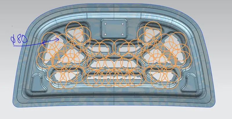
When we apply one mastic point it covers up to 80mm diameter around itself so like that we have to apply the mastic points and the distance between the inner panel and outer should not be more than 5mm. The mastic points and their range is shown below in the inner panel as follows:
5.Hemming manufacturing for the outer panel:
As we already decided we are using the hemming method to join the inner panel and outer panel so for that we have to add an open hem on the outer panel with the given dimensions as shown in the below diagram with Given Hemming Dimensions:
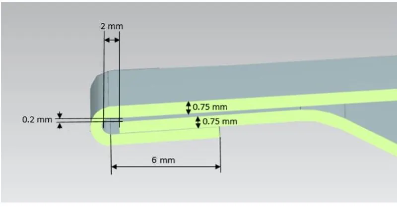
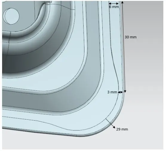
As we know that for the hemming process we use the rollers so when do rolling at a sharp corner we have to remove some material which is called bend relief, It is the notch that needs to be created for sheet metal bending. Bend relief helps control the sheet metal material behavior and prevents unwanted deformation. If we don't give bend relief then there is a greater amount of distortion or tearing of the adjacent material.
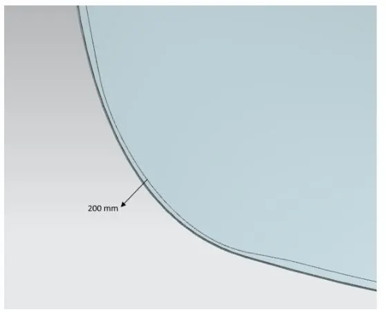
Dimensions of the bend relief are as follows for the outer panel:
6.Deciding the striker and hinge position:
Now we have designed the inner panel and outer panel so the next step is to fix the hinges and striker position as follows:
Steps to fix the Hing and striker position:
1. First we consider the hinge position on the inner panel to both left and right side, we adjust both the hinge in one line after that we draw the line which is passing through the axis of both hinges as shown in the diagram:
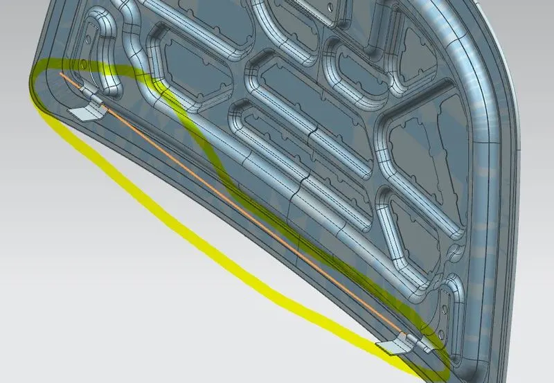
2. After this we draw the circle of any diameter through the midpoint of this line and draw some lines as shown in the figure to constraint the geometry:
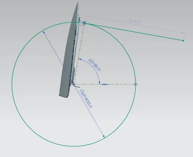
3.After this we sketch the striker as shown below:
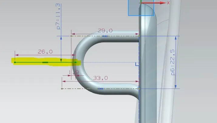
4. Now we add the assembly constraints which are as follows:
a.We give parallel constraints to the hinge axis and also to the striker with respect to the x-axis.
b. Now we give perfect touch constraints to the striker line and the tangent line of the circle.
c. Once again we give the perfect touch to the striker line point and the tangent line of circle point.
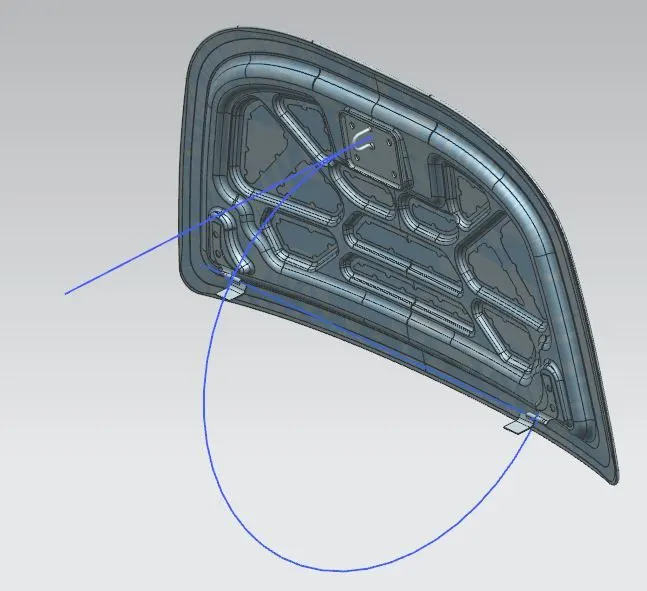
7.Mounting for hinges and strikers:
As we know that the inner panel surface is not straight it has some curvature so to mount the hinges or the striker we have to make the surface which is parallel to the surfaces of the hinges and striker and have to make emboss for mounting that on the inner panel as shown below
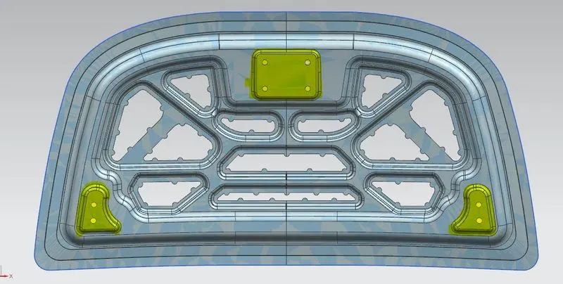
After this We have
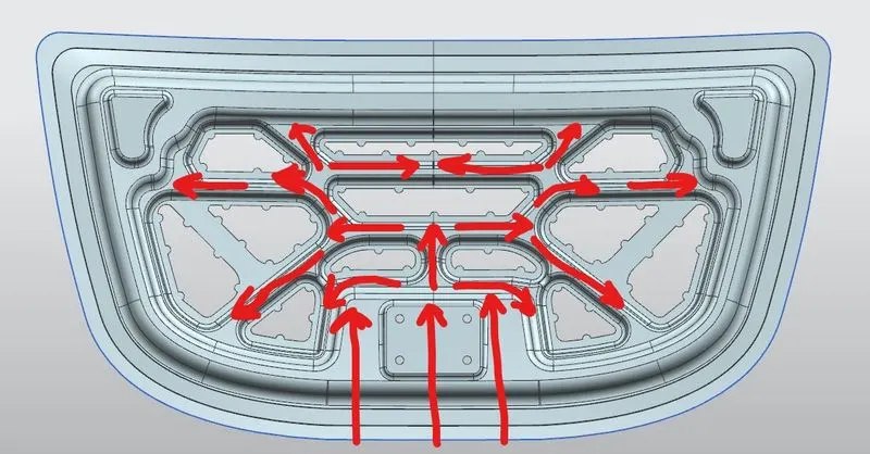
8.Frontal impact force transfer diagram:
We have to design the inner panel in such a way that when the frontal impact force strikes the car the most of the force should go outside the car not towards the driver or lobby.
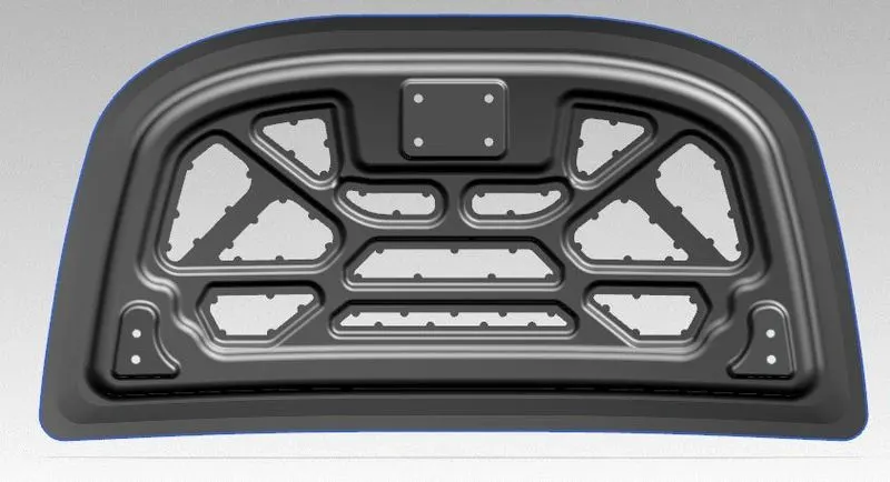
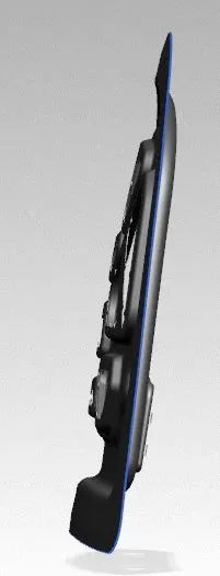
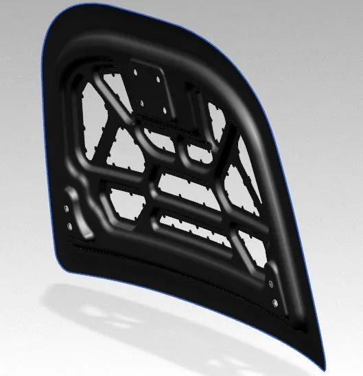
Images of the inner panel:
1.Front view
2.Side view:
3.Isometric View:
Images of the assembly of the Hood:
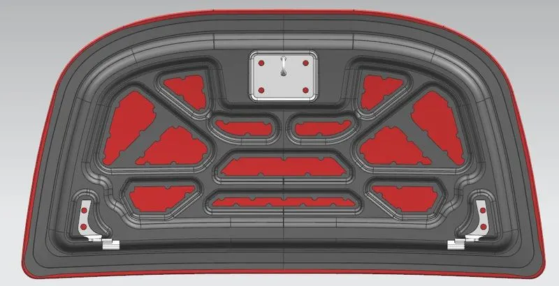
1.Bottom View:
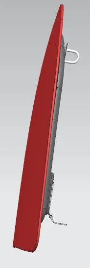
2.Side view:
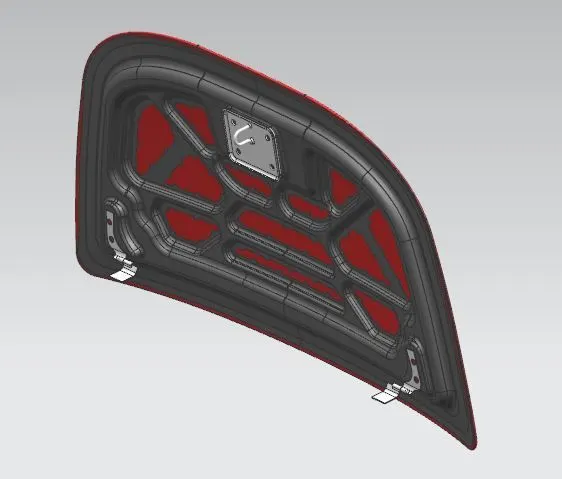
3.Isometric view:
Conclusion:
- from this, we learn how to design the inner panel with the given master sketch and outer panel according to the EURO-NCAP rules and according to the industrial manufacturability
- Learned how to define the position of the hinges and the striker with respect to each other so that while opening and closing the hood there should not be any clashes with other parts of the car.
- Learn different processes and methods used while manufacturing the inner panel, outer panel for design.