Design of backdoor
Aim: Design of the inner panel, hinge mounting, gas stay mounting, striker mounting. motor mounting on the inner panel of the back door.
Objectives:
- Study about the Back door assembly and constraints.
- Study about joining methods used to join the inner panel and outer panels of the back door.
- Learn how to find the latch and hinge mountings position.
- Learn how to add reinforcements to increase the strength at mountings areas.
Theory:
Backdoor/Tailgate: It is the fifth door located at the rear end of the car body. This door is used to cover and have easy access to our luggage space which is located at the rear end. In this project, we are provided with the styling surface of the outer panel.
Parts of thE Backdoor Assembly:
1.Outer Upper Panel
2.Outer Lower panel
3.Inner panel
4.Hinge Mounting Reinforcements
4.Gas stay mounting reinforcements
6.Wiper motor mounting reinforcement
7.Latch and striker mounting reinforcement
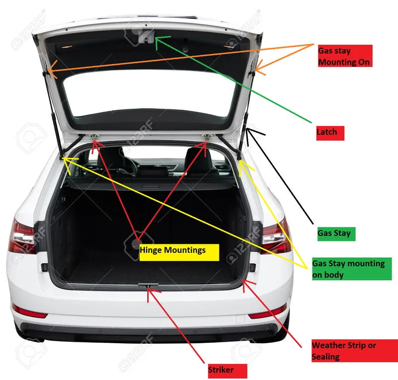
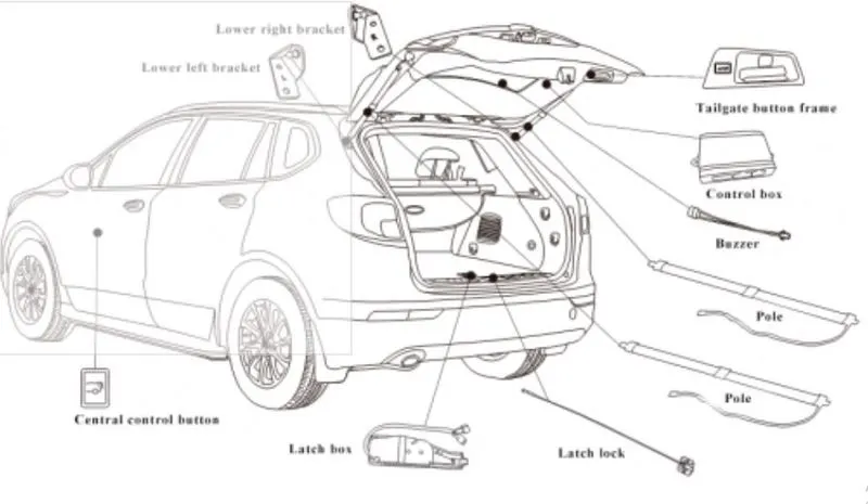
In this project, we are going to study and design the components of the backdoor by considering different aspects which are as follows:
- Material selection.
- Rear visibility criteria.
- Luggage capacity.
- Inner design according to the outer upper and lower panel.
- Hinge mounting location.
- Gas stay/powerlifter location.
- Latch and striker location according to the hinge mounting.
- Reinforcement for hinge, Gas stay wiper motor and latch mounting.
- Joining methods for the inner panel, outer panels, and reinforcements.
- Adding emboss for increasing the strength for crash analysis.
Types of the Backdoors based on the mounting of the gas stay and hinge:
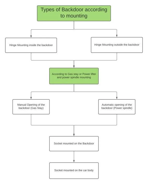
Selection of the materials:
For the inner panel, outer panel, reinforcements, we have two options steel and aluminum so let's compare both the materials as follows,
| Steel | Aluminum |
| Only one thickness have to maintain throughout the part | Thickness can be varied wherever we need to vary. |
| Manufacturing of the parts done with the help of the stamping process | Manufacturing of the parts done with the help of the casting |
| We need reinforcement to increase the strength of the particular area. | No need for reinforcement for aluminum |
| Weight is more compared to aluminum. | Weight is less compared to the steel |
| Cost is less and manufacturability is more than aluminum | cost is high and constraints on the manufacturability of the aluminum. |
As cost is the biggest parameter because we can reduce weight by doing rigorous analysis so we are selecting steel material.
Making selection for the thickness of the parts:
1.Outer panel: The thickness for steel should be between 0.5 to 1mm do we are selecting 0.75mm thickness.
2.Inner panel: The thickness of the inner panel is 0.75mm.
3.Reinforcements: The reinforcement is provided at the hinge mounting, gas stay mounting, wiper motor mounting, and latch mounting which is the thickness of 1.5mm.
Type of the Joining Methods:
1.Hemming:
It is a process in which we bend the sheet metal plate through 180° and it warped around the secondary sheet. This process consists of three processes as follows:
a.Flanging: In this step, we bend the sheet through 90° at the edge of the sheet.
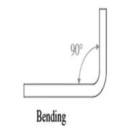
b.Pre-hemming: In this step, we bend the sheet in between 100° to 150°. This step is done to avoid the fracture and spring back effect of the sheet. Normally for the pre-hemming, we take a 135° angle.
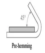
c.Hemming: This is the last step of the process in this sheet is bent to 180°

After this, we have to classify the hemming according to the '2t' or '3t' which refers to the single sheet or two sheets(inner and outer sheet)
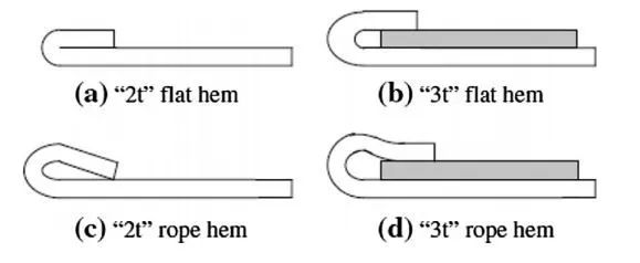
Types of the hemming:
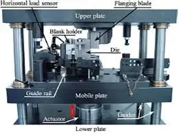
1.classical(conventional) hemming: In this process, the bending of the sheet is done with the help of the conventional punch method.
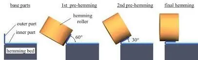
2.Rolling method: In this method, the roller is used for the bending of the sheet metal. In this method, we tilt the arm for the different angles of the roller. The advanced types of methods are robot-assisted roller hemming, laser-assisted roller hemming.
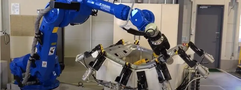
2.Brazing Process: It is a metal-joining process in which two or more metal items are joined together by melting and flowing a filler metal into the joint, with the filler metal having a lower melting point than the adjoining metal. As the filler metal has a lower melting point so it melts first and flows into the gaps available between two metals like a capillary action so it is different from the welding and soldering.
3.Mastics: In this, we use the mastic materials to join the two sheets. The mastics are used as a sealant or adhesive bond in joining.
Tooling Direction:
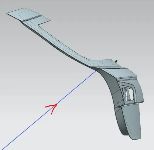
This is one of the most important steps while designing parts of the backdoor because we can design any type of shape but what if it is not able to manufacture so we have to decide the tooling direction for the stamping process and other operations for manufacturing the inner panel and outer panel and other parts before starting to design the components.
Tooling Direction:
Step followed for the design of the backdoor assembly:
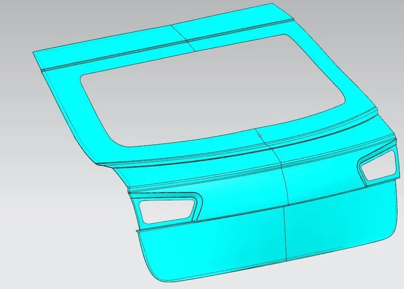
1.Outer panel:
- Getting styling surface of the outer panel from styling team.
- Splitting outer panel into upper and lower sections.
- Making corrections in the upper panels(removing all the irregular gaps between any two consecutive surfaces and adding edge bland at proper position)
- making a surface for joining the upper and lower outer panel by the brazing method.
- Joining the inner panel and outer panels with the help of the hemming process.
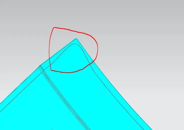
- Adding relief at the corners of the hemming to avoid the wrappage of material at the corners of the sheet.
Adding relief at the corners of the hemming.
2.Inner Panel:
- First, we have to decide the thickening direction for the outer panel and inner panel, which is shown in the following diagram.
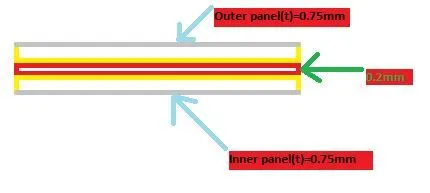
- So from the above diagram, we have to offset the outer panel surface to 1.7mm for reference to the inner panel.
- Now we don't have any sealing reference from the body so we create our sealing reference and give it to the body department.
- While creating sealing we have to consider the tooling direction.
- After creating sealing we have to make the surface for the latch and striker mounting and we have to do the emboss on that surface to increase the strength of the inner panel. Usually, we add V or Y emboss to transfer force to the outside area i.e. away from the passengers.
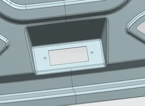
- Before making emboss we have to decide the latch position so for that we have to fix the position of hinge mounting on the inner panel. after that, by using the following geometry we decide the latch position.
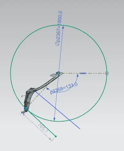
- Now we have a latch position based on the hinge position for the smooth open and close operation of the backdoor,
- Now we have to decide the position of the gas stay mounting on the inner panel, for the more opening of the backdoor we have kept gas stay mounting on the inner panel near to the hinge axis.
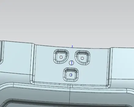
- We have also the wiper motor mounting on the inner panel near the wind still area.
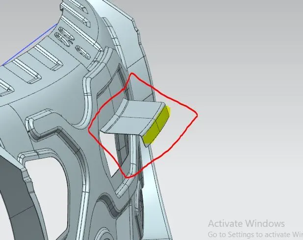
- As we already know the inner panel is joined to the outer panel with the help of the hemming process at the outer edge. But we don't have any joining in the middle surface so for that we cut the flange in the middle surface for the mastic points, as shown below figure.
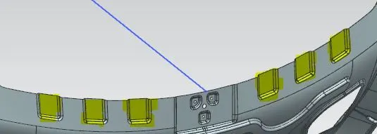
- For connecting the windshield to the inner panel we have given stripers on the inner panel.
Images of the inner panels:
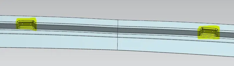
i).Hinge mountings:
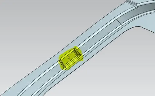
ii) Gas Stay mounting:
iii) Latch mounting:
iv) Motor Mounting:
v) Windshield mounting:
Inner panel design Image:
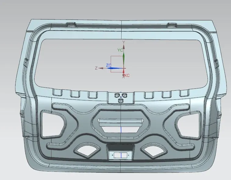
3.Reinforcements:
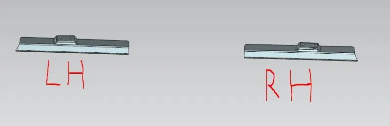
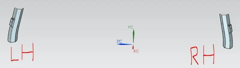
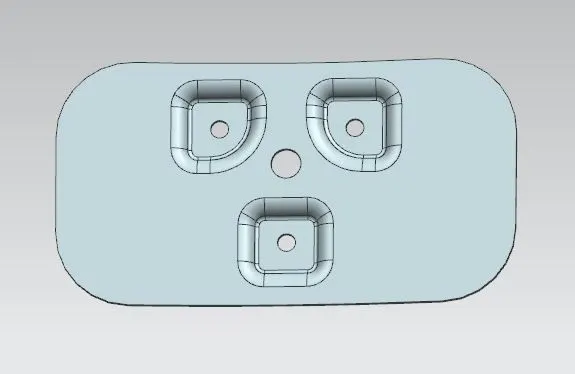
We add reinforcements to areas where sheet metal is weak and the forces are comings. The area near the mounting is weak and on that surface, forces are coming continuously so we add the reinforcements near that area which is of the thickness of 1.5mm to increase regional strength at that area. All reinforcements are joined either by the brazing process or the spot welding process.
a.) Hinge mounting reinforcement:
b.) Gas stay mounting reinforcement:
c. Wiper motor mounting reinforcement:
d. Latch mounting reinforcement:
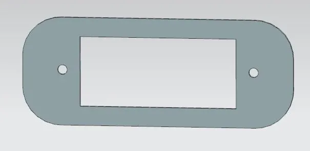
Draft analysis:
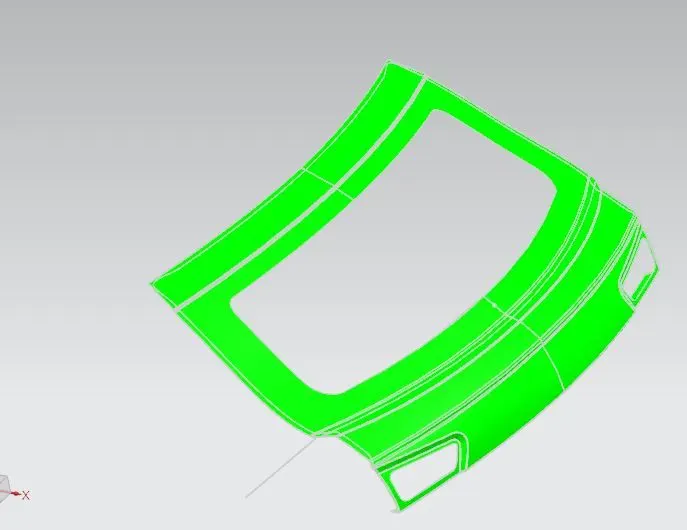
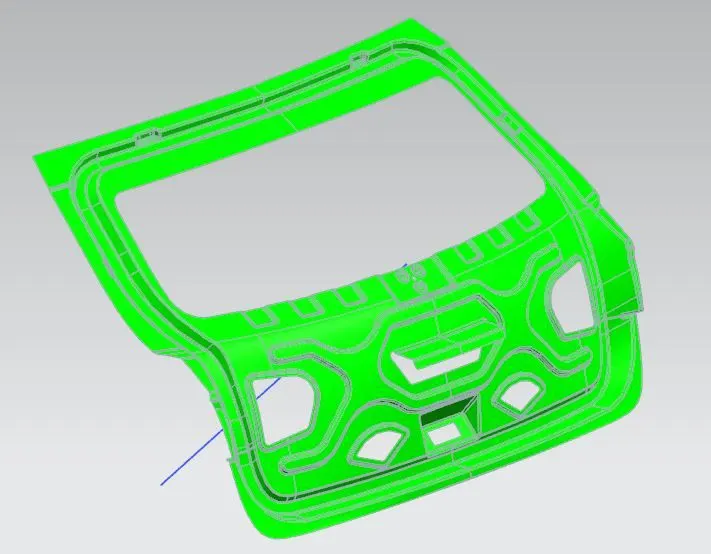
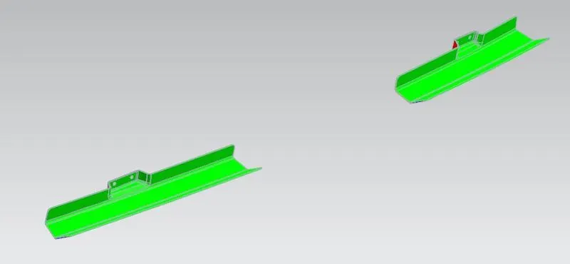
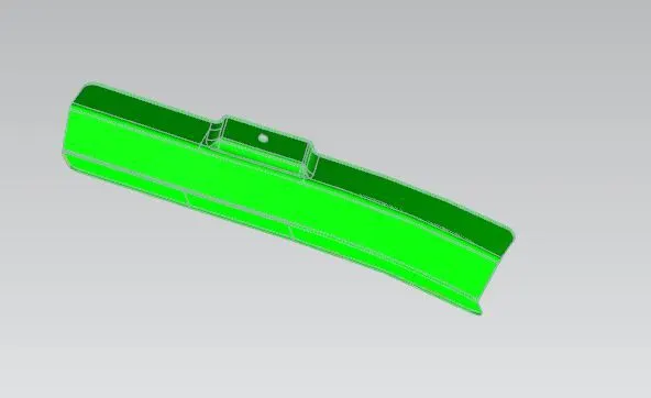
We do a draft analysis to check the manufacturability of the parts. For steel, the minimum draft angle is 7° so according to that, we get the following results. The green color shows that the part can be manufactured for this draft angle. So let us see the result for different parts of the backdoor. we are considering tooling direction same for all parts.
a. Outer panel:
1.Outer upper panel:
2.Outer lower panel: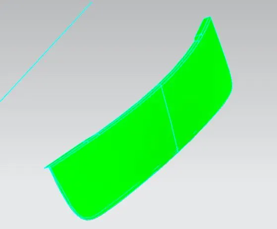
3.Inner panel:
4.Hinge mounting reinforcement:
5.Gas stay mounting reinforcement:
Assembly method:
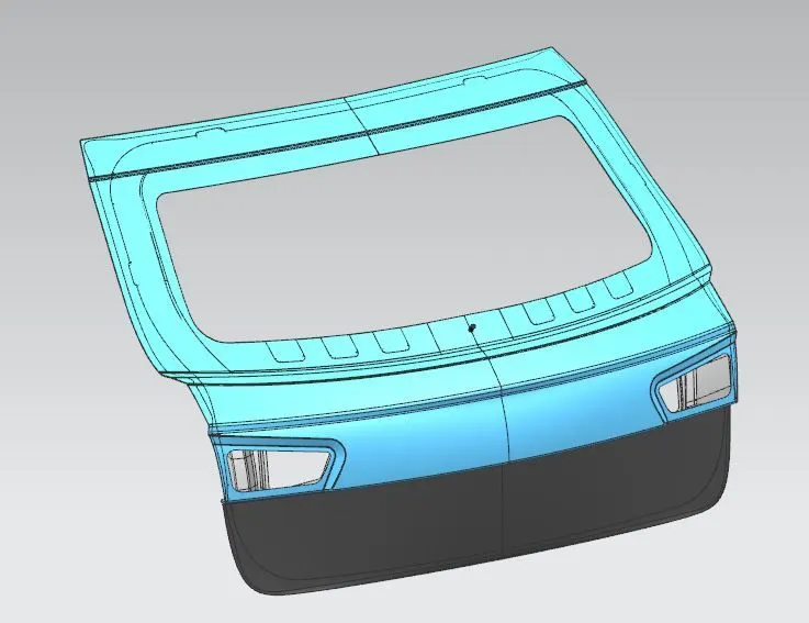
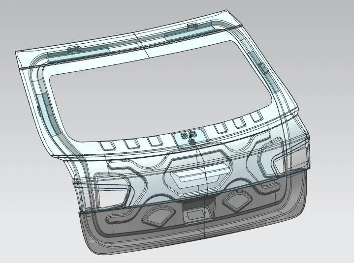
In the NX software, we used a top-down approach, In this approach, we first make the assembly files in the software, and then we call the reference surface in the assembly, and by using this surface we make other parts within the assembly. So according to this we first called the outer upper and lower section and using this surface and using wave geometry linker command in the NX software we designed the inner panel, that using the inner panel as a reference we designed the hinge mounting, gas stays mounting, motor mounting, and latch mounting. After joining the inner panel and outer panels by hemming process so it is impossible to disjoint them so for easy access to the removing and joining the back we have given the pockets in the inner panels.
Images of the assembly:
Conclusion:
From this project learned how industries work from benchmarking to designing the automotive components, studied a different type of manufacturing process, design constraints for designing parts of the backdoor, how to approach the problem and how to find solutions.