Box Assembly using NX sheet metal
Aim: Design the box assembly of sheet metal in Nx software.
Objectives:
- Learn how to approach the assembly of sheet metal parts.
- Learn what the command used to make sheet metal parts.
Introduction:
In this, we are learning how to use different commands for making box assembly of sheet metal in Nx Software. Basically, this box assembly is made from 1 mm thick sheet metal.
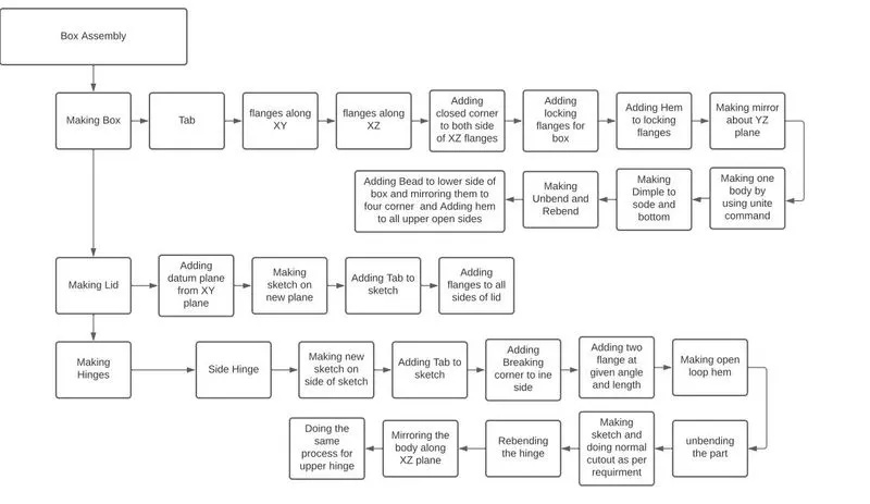
Flowchart:
Tools and features used for modeling Box Assembly:
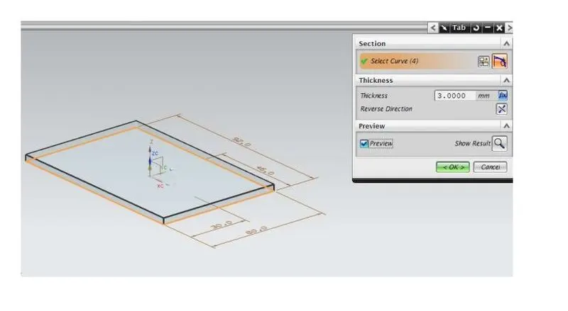
1.TAB: Creates a base feature by extruding a sketch along a vector by a thickness value or adds material to a plane face.
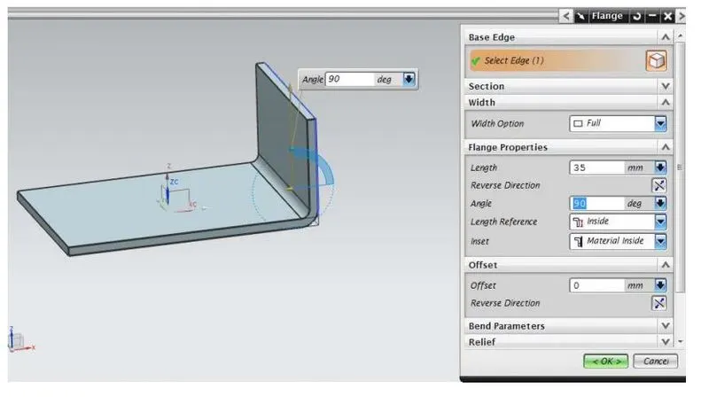
2.FLANGE: Adds a flange to an angle to a planar face and adds a bend between the two.
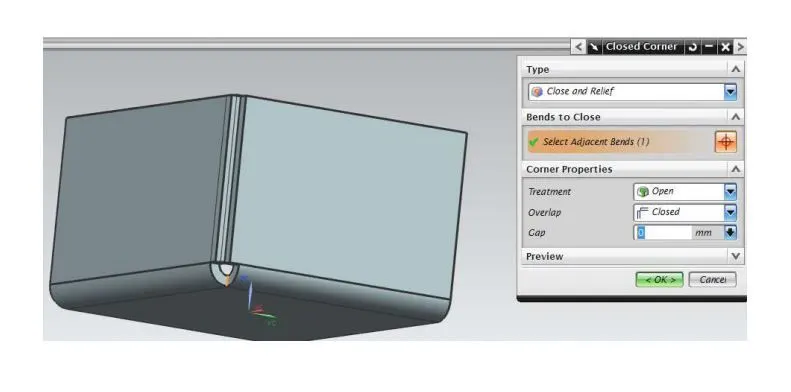
3. CLOSED CORNER: closes a corner where two adjacent flanges meet by extending the bends & flanges.
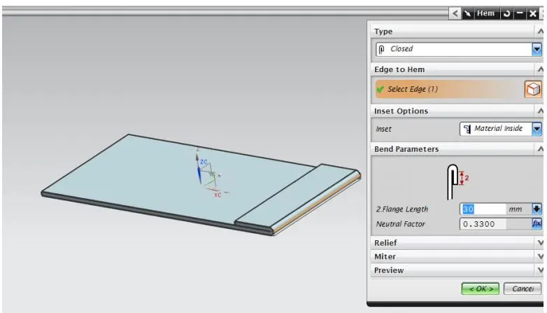
4. HEM FLANGE: Modifies the model by folding the edge of a sheet metal flange over onto itself for the purpose of safe handling or to increase edge stiffness.
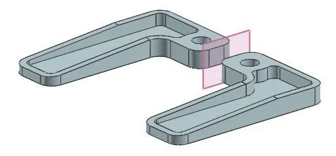
5.Mirror Body: command to mirror an entire body across a datum plane. For example, you can use this command to form the other hand of a left hand or right hand part.
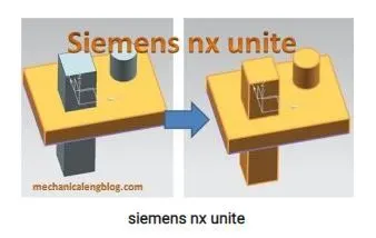
6.Unite: Used to combine the volume of two or more solid bodies into a single body. The target body and tool bodies must overlap or share faces.
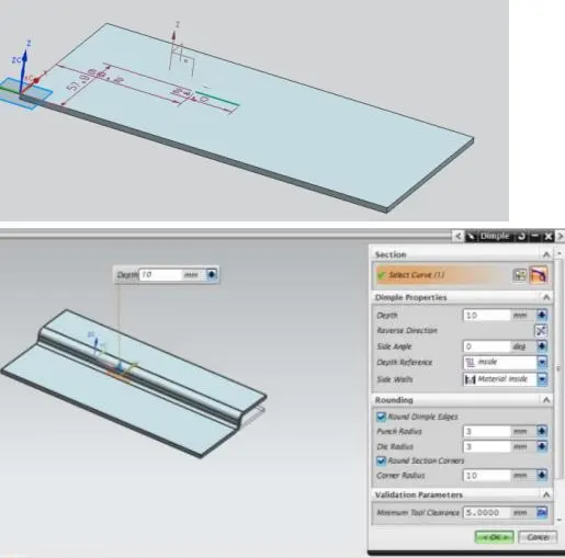
7.DIMPLE: Lifts an area of the model inside a sketch that simulates stamping a tool.
8.Unbend:Flattens a bend.
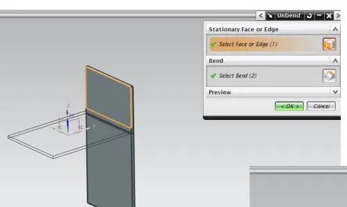
9.Rebend:Restores a bend.
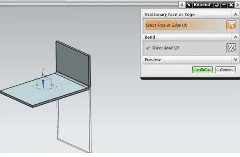
10.BEAD: Lifts a material along a counter of sketch that simulates stamping a tool.
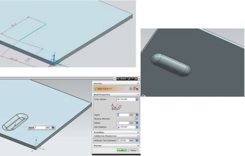
11.Datum Plane:A datum plane is a plane on the target that is established as a datum. It can be a target's external plane (datum plane) or center plane (datum center plane).
12.BREAK CORNER: Rounds a sharp corner
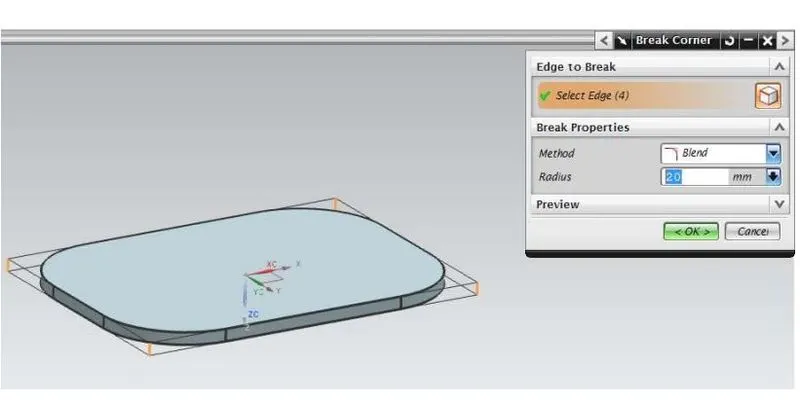
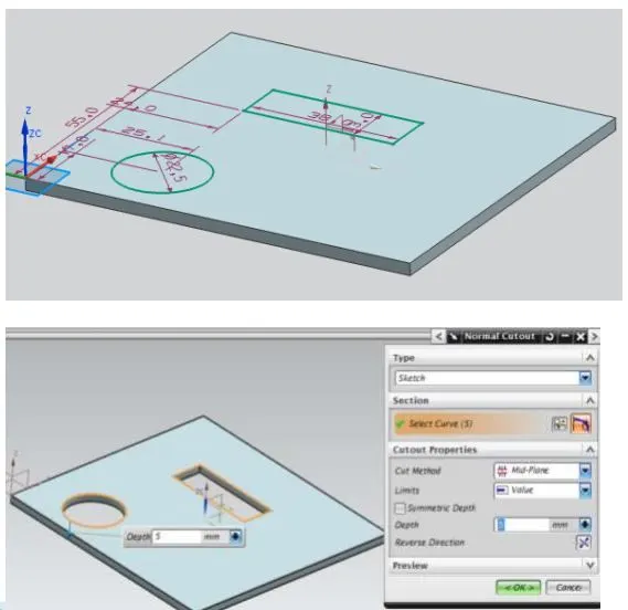
13.NORMAL CUTOUT: Cuts the model perpendicular to the sketch.
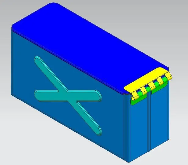
Images of the Box Assembly:
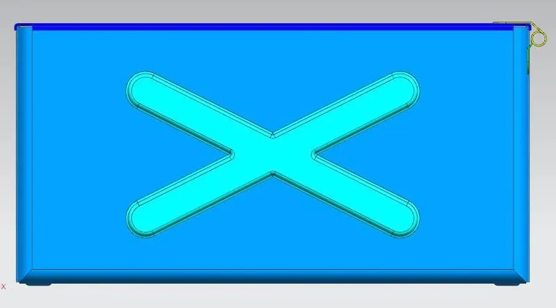
1.Front View:
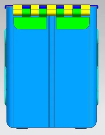
2.Side View:
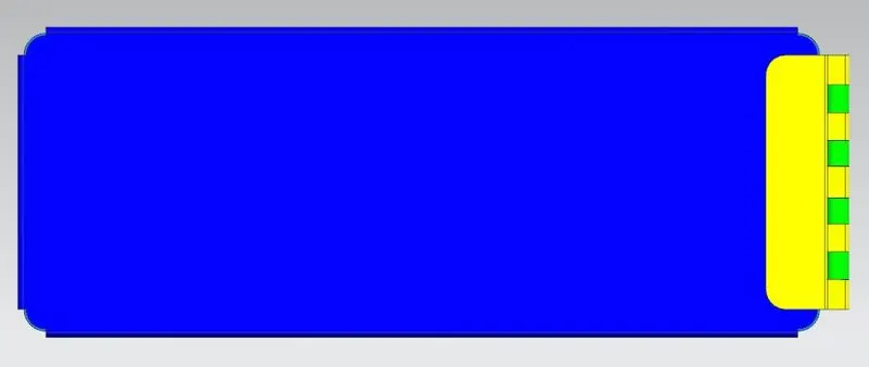
3.Top View:
4.Isometric View:
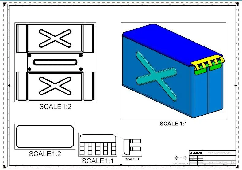
Drafting of the Box Assembly:
Conclusion:
Finally the box assembly is made with sheet metal by using Nx Software.Learned about parameters used make model with sheet metal.