To plan a structural layout and to create grids using TSD
CHALLENGE 1
- Summarize the user interface in TSD with the for the following items: -
Aim :
To summarize the user interface in Tekla Structural Designer. The following items need to be summarized:
- Project Workspace
- Scene Content
- Create two scene views
- Loading drop list
- Properties windows
Introduction:
Tekla Structural Designer is a software that allows us to design reinforced concrete buildings and steel buildings. The user interface in TSD comprises of a Quick Access Tool bar, Ribbon tools, Project Workspace, Scene Content, Loading list and Properties Windows.
Project Workspace:
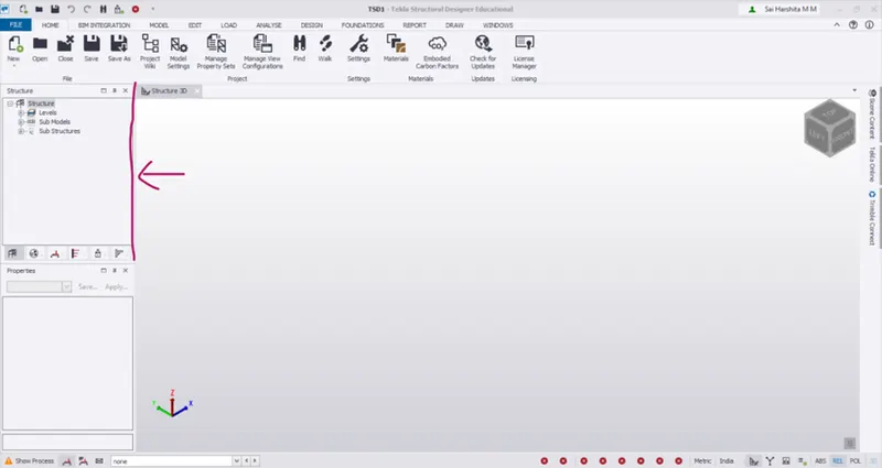
- The project workspace is seen in the left part of the window
- It consists of 6 options at the bottom viz.,
- Structure – Gives information on various construction levels
- Groups – Manages groups for designs
- Loading – Information on load cases and combinations
- Wind – Information on wind direction and loading
- Status – Provides status on modelling, analysis and design
- Connections – Information on connections used in the model
Scene Content:
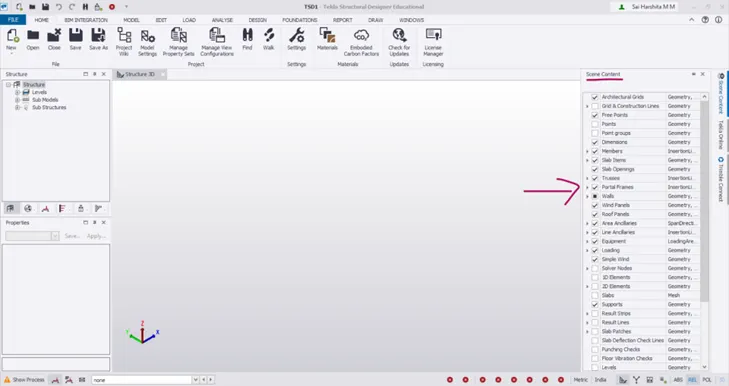
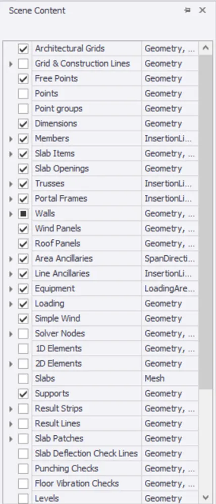
- Scene content contains the list of all members of the structure and helps in display of a particular member when ticked. The members to be hidden could be unticked so that it disappears from the view
Create 2 scene views:
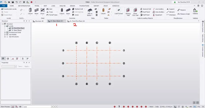
- Scene views are created to view the project in different levels/ in 3 dimensional view
- For instance, if a G + 1 level is created, 2 scene views can be created as follows
- Draw grid lines and fix levels using Construction levels
- Now go to Project Workspace to choose the levels
Loading drop list:
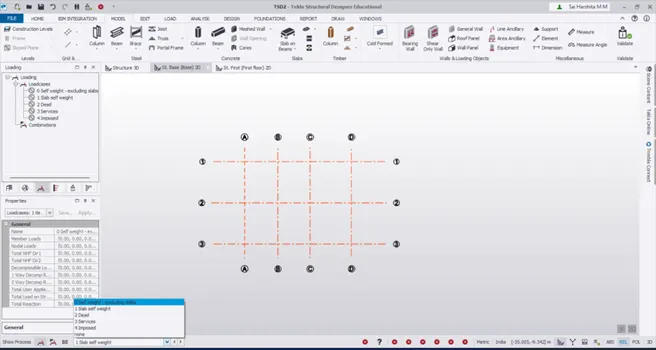
- Loadings list is seen in the Project Workspace
- The load cases and its various combinations could be seen
Properties Windows:
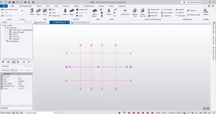
- Properties Window could be seen below the Project Workspace
- If we select any member/ gridlines in the workspace, the properties pertaining to it will appear under the Properties Window
Result:
Summarized the user interface in TSD for the following items: -
- Project Workspace – How to access and usage
- Scene Content – Demonstrate the use of scene content
- Create two scene views
- Loading drop list- How to access
- Properties windows – how to access and usage
2. Aim : To create a new file in TSD and set up the settings for a steel building to have member grade FE410 and concrete grade of M30 as per IS codes. The covers for the members to be as per the following input: -
|
MEMBERS |
IN CONTACT WITH GROUND |
ABOVE GROUND |
|
Column |
50mm |
40mm |
|
Slab |
30mm |
25mm |
|
Pile cap |
75mm |
|
|
Foundation |
50mm |
Introduction:
To start with any analysis and design in the software, the units, design codes, the materials used and cover to various members need to be entered
Procedure:
- Launch Tekla Structural Designer
- Go to File – New and save the workspace
- All the menus and tools will be active now
- Now go to Home – Materials
- Choose Materials
- Under Material type – Steel , choose Fe 410 WA as default
- Under Material type – Concrete , choose M30 as default
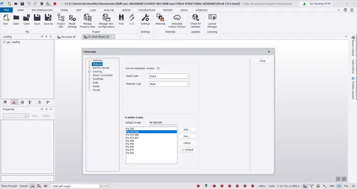
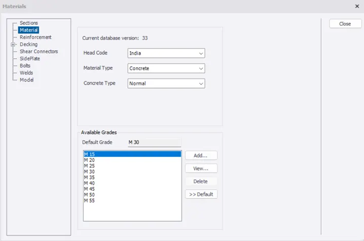
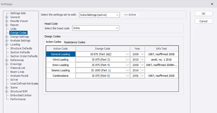
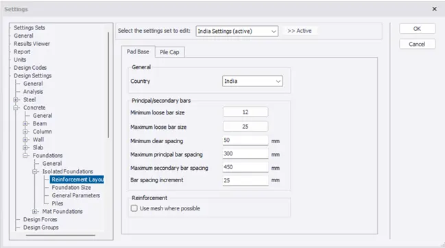
- Under Home – Settings, check for Units – Metric and in Design codes , Head Code – India
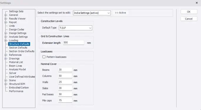
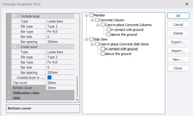
- Under Structural Defaults , Construction levels – TOF (members in contact with ground), enter the cover to the members as in question
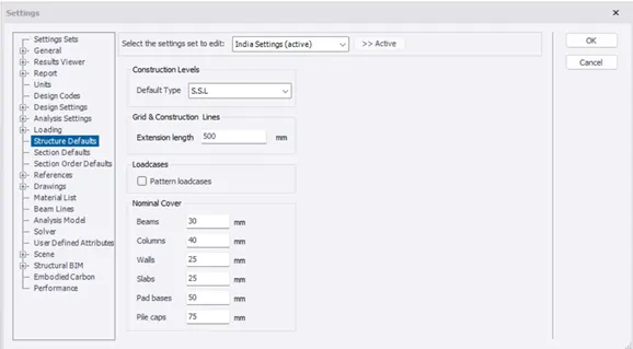
- Similarly, Under Structural Defaults , Construction levels – SSL (members above ground), enter the cover to the members as in question
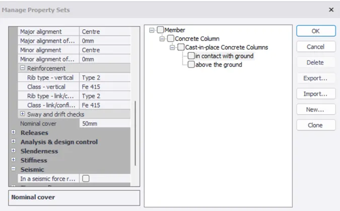
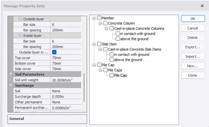
- We can also change the cover from Home – Manage Property Set – New – Members – Concrete Column
Result:
- The materials for steel and concrete are thus entered as Fe 410 and M30 respectively using Materials menu
- The covers of various members in contact with ground and above ground are thus set from Settings menu
- Aim :
- To study the steel building plan with reference to the input drawing as given in the attachment and to summarize the understanding of the plan.
- To explain the location of columns and beam and to develop a hand sketch for each plan
Introduction:
The first and foremost step of any structural planning is to carefully study the structural drawing and to place the columns and beams. While placing the columns the following points are to be considered:
- Columns should not be placed where there are door openings and where it hinders the available space
- Columns should be placed at all the corners and intersection of beam or walls
- Columns should be placed where the c/c distance between the columns is large
Procedure:
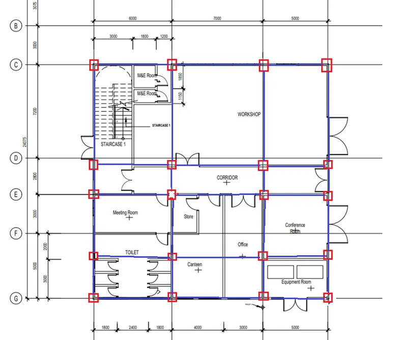
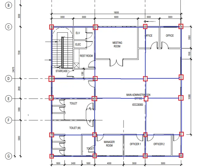
Ground Floor (Attachment 1):
- Columns are placed from the grid lines C through G and 1 through 4
- No problems were encountered while placing columns in grid C, E and G
- But in grid D , there was a door opening and hence the column is shifted to half a column distance
- Similarly in grid F, columns could not be placed since a door was encountered
- So columns are placed 2m from grid F
First floor ( Attachment 1.1):
- Same column positions are given to the first floor also to ensure there are no floating columns and there is a perfect frame
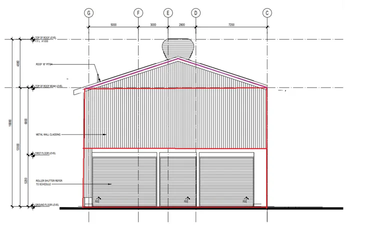
Section ( Attachment 1.2):
- The rafters are provided from the roof beam level till the roof level
- The purlins are also provided on the rafters
Result:
The beams and columns in the plan are thus preliminarly planned considering the openings, available spaces and spacing between members
- Aim:
To model grid lines and construction levels as per the attachment
Introduction:
Grid lines are helpful to place the columns and beams
Construction levels contains information on the number of levels in the project and heights of each level
Procedure:
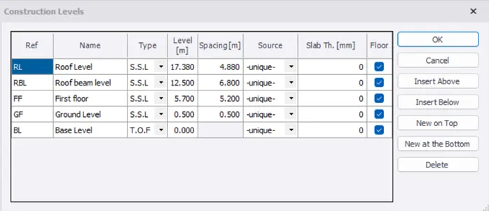
- Go to Model – Construction Levels
- Open the section drawing and enter the level details one above the other
- Start from Base level followed by GF, FF, RBL,RL at 0.5m, 5.2m, 6.8m, 4.88m respectively
- Click OK
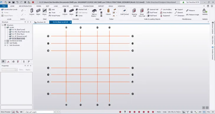
- Go to Model – Grid – Grid line
- Start from the vertical grid line 1
- Check the plan and enter the grid spacing accordingly by using Parallel quick grid line option
- After drawing vertical grids, click on Perpendicular under Grids and draw the horizontal grid A
- Draw the subsequent grids with correct spacing
- Go to Model – Dimension and mark the dimension
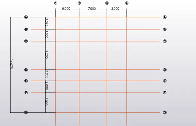
Result:
The construction levels and grid lines are thus created as per the given attachment